
creative commons mud pump oil and gas manufacturer

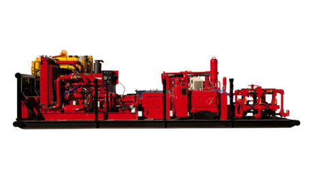
The 2,200-hp mud pump for offshore applications is a single-acting reciprocating triplex mud pump designed for high fluid flow rates, even at low operating speeds, and with a long stroke design. These features reduce the number of load reversals in critical components and increase the life of fluid end parts.
The pump’s critical components are strategically placed to make maintenance and inspection far easier and safer. The two-piece, quick-release piston rod lets you remove the piston without disturbing the liner, minimizing downtime when you’re replacing fluid parts.

If you ended up on this page doing normal allowed operations, please contact our support at support@mdpi.com. Please include what you were doing when this page came up and the Ray ID & Your IP found at the

Mickan Tool and Supply stocks API 7F Certified oilfield roller chain that is designed to resist wear and fatigue for longer life.Oil & gas roller chain applications for drawworks, mud pumps, transmission drives, catshafts, and rotary countershafts.Mickan Tool and Supply offers standard 10 foot box length and can also cut roller chain to exact pitch size.Mickan Tool and Supply also stocks common roller chain connecting links and offset links.
We stock API 7F certified oilfield roller chain, which has superior fatigue and shock load resistance providing maximum performance and reliability. If you are operating or repairing drawworks, mud pumps, catshafts, or countershafts, we can supply the best roller chain and roller chain parts to meet your requirement.

Gardner Denver, Lewco, NOV, Oilwell, National, Varco, Woolley, Baash-Ross, Demco, Bomco, Oteco, Brown & Sharpe, Ideco, P-Quip, and Continental Emsco, and the product models referenced on this website are trademarks or registered trademarks of their respective companies. Premium Oilfield Technologies is not authorized by or affiliated with any of these companies, and no business relationship, affiliation, or endorsement is claimed or implied.

Our state-of-the-art repair facilities combine world-class equipment with over 150 years of industry leading expertise, to provide our customers with a comprehensive range of services. If you can’t come to us, we can bring our legendary expertise to you, using our full range of on-site repair and field service offerings.
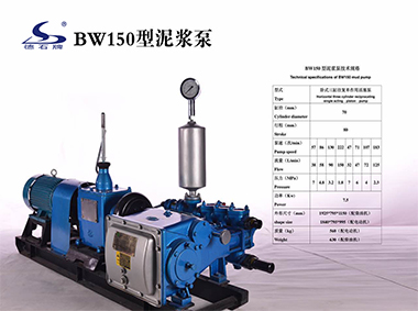
A mud pump (sometimes referred to as a mud drilling pump or drilling mud pump), is a reciprocating piston/plunger pump designed to circulate drilling fluid under high pressure (up to 7,500 psi or 52,000 kPa) down the drill string and back up the annulus. A mud pump is an important part of the equipment used for oil well drilling.
Mud pumps can be divided into single-acting pump and double-acting pump according to the completion times of the suction and drainage acting in one cycle of the piston"s reciprocating motion.
Mud pumps come in a variety of sizes and configurations but for the typical petroleum drilling rig, the triplex (three piston/plunger) mud pump is used. Duplex mud pumps (two piston/plungers) have generally been replaced by the triplex pump, but are still common in developing countries. Two later developments are the hex pump with six vertical pistons/plungers, and various quintuplexes with five horizontal piston/plungers. The advantages that these new pumps have over convention triplex pumps is a lower mud noise which assists with better measurement while drilling (MWD) and logging while drilling (LWD) decoding.
The fluid end produces the pumping process with valves, pistons, and liners. Because these components are high-wear items, modern pumps are designed to allow quick replacement of these parts.
To reduce severe vibration caused by the pumping process, these pumps incorporate both a suction and discharge pulsation dampener. These are connected to the inlet and outlet of the fluid end.
Displacement is calculated as discharged liters per minute. It is related to the drilling hole diameter and the return speed of drilling fluid from the bottom of the hole, i.e. the larger the diameter of drilling hole, the larger the desired displacement. The return speed of drilling fluid should wash away the debris and rock powder cut by the drill from the bottom of the hole in a timely manner, and reliably carry them to the earth"s surface. When drilling geological core, the speed is generally in range of 0.4 to 1.0 m^3/min.
The pressure of the pump depends on the depth of the drilling hole, the resistance of flushing fluid (drilling fluid) through the channel, as well as the nature of the conveying drilling fluid. The deeper the drilling hole and the greater the pipeline resistance, the higher the pressure needed.
With the changes of drilling hole diameter and depth, the displacement of the pump can be adjusted accordingly. In the mud pump mechanism, the gearbox or hydraulic motor is equipped to adjust its speed and displacement. In order to accurately measure the changes in pressure and displacement, a flow meter and pressure gauge are installed in the mud pump.
The construction department should have a special maintenance worker that is responsible for the maintenance and repair of the machine. Mud pumps and other mechanical equipment should be inspected and maintained on a scheduled and timely basis to find and address problems ahead of time, in order to avoid unscheduled shutdown. The worker should attend to the size of the sediment particles; if large particles are found, the mud pump parts should be checked frequently for wear, to see if they need to be repaired or replaced. The wearing parts for mud pumps include pump casing, bearings, impeller, piston, liner, etc. Advanced anti-wear measures should be adopted to increase the service life of the wearing parts, which can reduce the investment cost of the project, and improve production efficiency. At the same time, wearing parts and other mud pump parts should be repaired rather than replaced when possible.
For the successful execution of your projects, it is important to find an appropriate company with a good track record. We help you in connecting with the top mud pump manufacturers and companies and get the best quotation.
We have designed affordable annual subscription plans which would help you get leads for your business. You can have a look at our pricing chart by clicking on this link: https://www.energydais.com/pricing/ . These plans are customized according to the specific needs and requirements of your business.
The most widely used mud pumps across the industry are Triplex Reciprocating Pumps. Their application has gained immense popularity with time because they are 30% lighter than duplex reciprocating pumps with relatively less operational cost. Moreover, through these pumps the discharge of mud is smooth and they are capable of moving large volume of mud at higher pressure.
Yes. We help you find the best mud pumps irrespective of your location. We simplify your search by connecting you with top mud pump manufacturers and mud pump companies in your location, according to your budget and business requirement.
Yes. We use third-party companies to provide best quotations for your shipment and inspection of manufactured goods. We make sure that you get quality products from the manufacturer at the best price.
The most widely used mud pumps across the industry are Triplex Reciprocating Pumps. Their application has gained immense popularity with time because they are 30% lighter than duplex reciprocating pumps with relatively less operational cost. Moreover, through these pumps the discharge of mud is smooth and they are capable of moving large volume of mud at higher pressure.
The different parts of a mud pump are Housing itself, Liner with packing, Cover plus packing, Piston and piston rod, Suction valve and discharge valve with their seats, Stuffing box (only in double-acting pumps), Gland (only in double-acting pumps), and Pulsation dampener. A mud pump also includes mud pump liner, mud pump piston, modules, hydraulic seat pullers along with other parts.
The wearing parts of a mud pump should be checked frequently for repairing needs or replacement. The wearing parts include pump casing, bearings, impeller, piston, liner, etc. Advanced anti-wear measures should be taken up to enhance the service life of the wearing parts. This can effectively bring down the project costs and improve production efficiency.

Researchers have shown that mud pulse telemetry technologies have gained exploration and drilling application advantages by providing cost-effective real-time data transmission in closed-loop drilling operations. Given the inherited mud pulse operation difficulties, there have been numerous communication channel efforts to improve data rate speed and transmission distance in LWD operations. As discussed in “MPT systems signal impairments”, mud pulse signal pulse transmissions are subjected to mud pump noise signals, signal attenuation and dispersion, downhole random (electrical) noises, signal echoes and reflections, drillstring rock formation and gas effects, that demand complex surface signal detection and extraction processes. A number of enhanced signal processing techniques and methods to signal coding and decoding, data compression, noise cancellation and channel equalization have led to improved MPT performance in tests and field applications. This section discusses signal-processing techniques to minimize or eliminate signal impairments on mud pulse telemetry system.
At early stages of mud pulse telemetry applications, matched filter demonstrated the ability to detect mud pulse signals in the presence of simulated or real noise. Matched filter method eliminated the mud noise effects by calculating the self-correlation coefficients of received signal mixed with noise (Marsh et al. 1988). Sharp cutoff low-pass filter was proposed to remove mud pump high frequencies and improve surface signal detection. However, matched filter method was appropriate only for limited single frequency signal modulated by frequency-shift keying (FSK) with low transmission efficiency and could not work for frequency band signals modulated by phase shift keying (PSK) (Shen et al. 2013a).
Wavelet transform method was developed and widely adopted and used in signal processing to overcome limitation of Fourier transform in time domain (Bultheel 2003). Although Fourier and its revised fast Fourier transforms are powerful mathematical tool, they are not very good at detecting rapid changes in signals such as seismic data and well test data in petroleum industry containing many structure of different scales (Multi-scale structures) (Guan et al. 2004). Fourier coefficients do not provide direct information about the signal local behavior (localization); but the average strength of that frequency in the full signal as the sine or cosine function keeps undulating to infinity. Wavelet transform analyzes the signal frequency components and time segment, and fine tune sampling of localized characters of time or frequency domain. Principles of wavelet transform and de-noising technique show that signal can be divided into space and scale (time and frequency) without losing any useful information of the original signal, hence ensuring the extraction of useful information from the noised signal (Li et al. 2007). Different wavelet base parameters constructed, such as haar, db, coif, sym, bior, rbio and dmey, are suitable for different signal processing requirements. The small the scale parameter is, the higher the resolving power in frequency, suitable for processing high frequency signals; conversely, the larger the scale is the higher resolving power suitable for low frequency signal.
In processing noise-contaminated mud pulse signals, longer vanishing moments are used, but takes longer time for wavelet transform. The main wavelet transform method challenges include effective selection of wavelet base, scale parameters and vanishing moment; the key determinants of signal correlation coefficients used to evaluate similarities between original and processed signals. Chen et al. (2010) researched on wavelet transform and de-noising technique to obtain mud pulse signals waveform shaping and signal extraction based on the pulse-code information processing to restore pulse signal and improve SNR. Simulated discrete wavelet transform showed effective de-noise technique, downhole signal was recovered and decoded with low error rate. Namuq et al. (2013) studied mud pulse signal detection and characterization technique of non-stationary continuous pressure pulses generated by the mud siren based on the continuous Morlet wavelet transformation. In this method, generated non-stationary sinusoidal pressure pulses with varying amplitudes and frequencies used ASK and FSK modulation schemes. Simulated wavelet technique showed appropriate results for dynamic signal characteristics analysis.
While Fourier coefficients provide average signal information in frequency domain and unable to reveal the non-stationary signal characteristics, wavelet transform can effectively eliminate MPT random noise when signal carrier frequency characteristics (periods, frequencies, and start and end time) are carefully analyzed.
As discussed in “MPT mud pump noises”, the often overlap of the mud pulses frequency spectra with the mud pump noise frequency components adds complexity to mud pulse signal detection and extraction. Real-time monitoring requirement and the non-stationary frequency characteristics made the utilization of traditional noise filtering techniques very difficult (Brandon et al. 1999). The MPT operations practical problem contains spurious frequency peaks or outliers that the standard filter design cannot effectively eliminate without the possibility of destroying some data. Therefore, to separate noise components from signal components, new filtering algorithms are compulsory.
Early development Brandon et al. (1999) proposed adaptive compensation method that use non-linear digital gain and signal averaging in the reference channel to eliminate the noise components in the primary channel. In this method, synthesized mud pulse signal and mud pump noise were generated and tested to examine the real-time digital adaptive compensation applicability. However, the method was not successfully applied due to complex noise signals where the power and the phases of the pump noises are not the same.
Jianhui et al. (2007) researched the use of two-step filtering algorithms to eliminate mud pulse signal direct current (DC) noise components and attenuate the high frequency noises. In the study, the low-pass finite impulse response (FIR) filter design was used as the DC estimator to get a zero mean signal from the received pressure waveforms while the band-pass filter was used to eliminate out-of-band mud pump frequency components. This method used center-of-gravity technique to obtain mud pulse positions of downhole signal modulated by pulse positioning modulation (PPM) scheme. Later Zhao et al. (2009) used the average filtering algorithm to decay DC noise components and a windowed limited impulse response (FIR) algorithm deployed to filter high frequency noise. Yuan and Gong (2011) studied the use of directional difference filter and band-pass filter methods to remove noise on the continuous mud pulse differential binary phase shift keying (DBPSK) modulated downhole signal. In this technique, the directional difference filter was used to eliminate mud pump and reflection noise signals in time domain while band-pass filter isolated out-of-band noise frequencies in frequency domain.
Other researchers implemented adaptive FIR digital filter using least mean square (LMS) evaluation criterion to realize the filter performances to eliminate random noise frequencies and reconstruct mud pulse signals. This technique was adopted to reduce mud pump noise and improve surface received telemetry signal detection and reliability. However, the quality of reconstructed signal depends on the signal distortion factor, which relates to the filter step-size factor. Reasonably, chosen filter step-size factor reduces the signal distortion quality. Li and Reckmann (2009) research used the reference signal fundamental frequencies and simulated mud pump harmonic frequencies passed through the LMS filter design to adaptively track pump noises. This method reduced the pump noise signals by subtracting the pump noise approximation from the received telemetry signal. Shen et al. (2013a) studied the impacts of filter step-size on signal-to-noise ratio (SNR) distortions. The study used the LMS control algorithm to adjust the adaptive filter weight coefficients on mud pulse signal modulated by differential phase shift keying (DPSK). In this technique, the same filter step-size factor numerical calculations showed that the distortion factor of reconstructed mud pressure QPSK signal is smaller than that of the mud pressure DPSK signal.
Study on electromagnetic LWD receiver’s ability to extract weak signals from large amounts of well site noise using the adaptive LMS iterative algorithm was done by (Liu 2016). Though the method is complex and not straightforward to implement, successive LMS adaptive iterations produced the LMS filter output that converges to an acceptable harmonic pump noise approximation. Researchers’ experimental and simulated results show that the modified LMS algorithm has faster convergence speed, smaller steady state and lower excess mean square error. Studies have shown that adaptive FIR LMS noise cancellation algorithm is a feasible effective technique to recover useful surface-decoded signal with reasonable information quantity and low error rate.
Different techniques which utilize two pressure sensors have been proposed to reduce or eliminate mud pump noises and recover downhole telemetry signals. During mud pressure signal generation, activated pulsar provides an uplink signal at the downhole location and the at least two sensor measurements are used to estimate the mud channel transfer function (Reckmann 2008). The telemetry signal and the first signal (pressure signal or flow rate signal) are used to activate the pulsar and provide an uplink signal at the downhole location; second signal received at the surface detectors is processed to estimate the telemetry signal; a third signal responsive to the uplink signal at a location near the downhole location is measured (Brackel 2016; Brooks 2015; Reckmann 2008, 2014). The filtering process uses the time delay between first and third signals to estimate the two signal cross-correlation (Reckmann 2014). In this method, the derived filter estimates the transfer function of the communication channel between the pressure sensor locations proximate to the mud pump noise source signals. The digital pump stroke is used to generate pump noise signal source at a sampling rate that is less than the selected receiver signal (Brackel 2016). This technique is complex as it is difficult to estimate accurately the phase difference required to give quantifiable time delay between the pump sensor and pressure sensor signals.
As mud pulse frequencies coincide with pump noise frequency in the MPT 1–20 Hz frequency operations, applications of narrow-band filter cannot effectively eliminate pump noises. Shao et al. (2017) proposed continuous mud pulse signal extraction method using dual sensor differential signal algorithm; the signal was modulated by the binary frequency-shift keying (BFSK). Based on opposite propagation direction between the downhole mud pulses and pump noises, analysis of signal convolution and Fourier transform theory signal processing methods can cancel pump noise signals using Eqs. 3 and 4. The extracted mud pulse telemetry signal in frequency domain is given by Eqs. 3 and 4 and its inverse Fourier transformation by Eq. 4. The method is feasible to solve the problem of signal extraction from pump noise,
\(H(\omega )={f^{ - 1}}h(t)=G(\omega ){e^{ - j\omega \tau }}\) is the Fourier transformed impulse response, \(h(t)\), data transmission between sensor A and sensor B.
These researches provide a novel mud pulse signal detection and extraction techniques submerged into mud pump noise, attenuation, reflections, and other noise signals as it moves through the drilling mud.

The Well Control System or the Blowout Prevention System on a drilling rig is the system that prevents the uncontrolled, catastrophic release of high-pressure fluids (oil, gas, or salt water) from subsurface formations. These uncontrolled releases of formation fluids are referred to as Blowouts. Due to the explosive nature of oil and gas, any spark on the surface can result in the ignition of the fluids and an explosion on the rig. An explosive blowout and the failure of the Well Control System were the causes of the Mocondo Well disaster that killed eleven of the rig crew on the Deep Water Horizon Rig on April 20, 2010 and resulted in 35,000 to 60,000 bbl/day of crude oil to spill into the Gulf of Mexico. We will discuss this later in the lesson.
The blowout preventers are the principal piece of equipment in the well control system and are operated hydraulically; pressurized fluids are used to operate pistons and cylinders to open or close the valves on the BOP. The Accumulators (Item 18 in Figure 9.02) are used to store pressurized, non-explosive gas and pressurized hydraulic fluid to run the hydraulics systems on the rig. The accumulators store enough compressed energy to operate the blowout preventers even if the Power System of the rig is not operating.
The blowout preventer is a large system of valves each of which is capable of isolating the subsurface of the well from the rig to provide control over the well. These valves are typically stacked as shown in the Figure 9.11 and sit below the rig floor on land wells or some offshore wells; or they may sit on the seabed on other offshore wells.
Figure 9.12 shows three type of valves (there are others) – an Annular Preventer, Blind Rams, and Shear Rams. The Annular preventer is the ring-shaped piece of equipment on the top of the BOP in Figure 9.11. As the name implies, the annular preventer is used to prevent flow through the annular space between the drill string or casing and the annular preventer. The annular preventer can also be used for non-cylindrical pipe, such as the kelly, or open hole. The annular preventer consists of a doughnut shaped bladder that when in the open position allows the drill pipe to rotate but in the closed position seals the annulus. Figure 9.13 provides a schematic of the annular preventer.
Schematics of the ram-type preventers: the blind rams, the shear rams, and the pipe rams (pipe rams are not shown in Figure 9.12) are shown in Figure 9.14.
control formation pore pressures to assure desired well control (apply hydrostatic and hydrodynamic pressures in excess of the formation pore pressures to prevent fluids from entering the wellbore);
In the first objective re-quoted above, if we can keep the pressure exerted by the drilling mud greater than the pore pressure, then we know that fluids will flow in the direction of the mud to the formation. This cannot always be achieved. For example, if we drill through a natural fracture or if our mud density is too great and we inadvertently fracture one formation, then we may lose large quantities of the drilling fluid into the fracture (Lost Circulation). In this situation, instead of having the full weight of the mud column exerting pressure on a second (porous and permeable) formation, we may only have a fraction of the oil column height exerting a lower pressure on that second formation.
In the second objective re-quoted above, if we deposit an impermeable Drill Cake (filter cake) across an otherwise porous and permeable formation, then for a slightly Underbalanced Pressure (drilling fluid pressure lower than the formation pressure) we have created a seal between the wellbore and the formation. Again, this is not a Failsafe System because at greater underbalanced pressures, the higher formation pressures may be able to displace the drill cake.
The two previously discussed methods are used to help prevent a kick from occurring, but as mentioned they are not always successful, and kicks may still occur. The causes of a kick include:
improper mud replacement during tripping: while tripping out of the hole mud volumes must be pumped into the wellbore at high enough rates to replace drill pipe being removed from the wellbore;
lost circulation: as discussed earlier if large volumes of drilling fluid enter the subsurface in (1) high permeability formations, natural fractures, or drilling-induced fractures, then the effect is a shortened height and weight of the mud column.
increase in the rate of flow of the drilling fluid returns at constant pump rates (primary indicator of a kick):The increased rate is caused by formation fluids entering the wellbore and is a strong indication of a kick. In addition, if it is a gas kick, due to the compressible nature of gas, as the gas bubble travels up-hole and hydrostatic pressures decrease, the volume of the bubble will increase due to expansion.
volume of mud in the mud pit increases when no additional drilling fluids are added to the mud system (primary indicator of a kick):For the same reasons as mentioned above, if the volume of mud in the mud pits increases when no additional fluids have intentionally added, then the increased volume is caused by formation fluids entering the wellbore and is a strong indication of a kick.
drilling fluids returns continue to flow when the mud pumps are turned off (primary indicator of a kick):Drilling fluid returns when the mud pumps are shut-off indicate that formation fluids are entering the wellbore and displacing the mud.
improper wellbore fill-up/volume-balance on trips (primary indicator of a kick):If the drill pipe is removed from the wellbore, then the change in volume in the mud pits should equal the volume of the drill pipe removed from the hole. An improper volume balance is a strong indicator of a kick.
pump pressure decrease and pump stroke increase (secondary indicator of a kick):If low density fluids are displacing heavier drilling fluid in the annulus, then this will cause the pump pressure to decrease (the annular side of the u-tube is lighter than the drill pipe side of the u-tube which contains the mud pump pressure gauge). The imbalance in the u-tube, just described, will cause the heavier drilling fluid in the drill pipe to fall due to gravity, causing the mud pump to increase the number of strokes to keep up with the pressure imbalance.
occurrence of a Drill Break or Bit Drop (secondary indicator of a kick):A Drill Break (sudden change in the rate-of-penetration) or Bit Drop (sudden increase in the drill bit depth) typically occur at a change in the lithology of the formation being drilled. In particular, a large bit drop may be an indication of drilling through a natural facture system. Both drill breaks and bit drops are normally recorded in the drilling records. When working on naturally fracture reservoirs, these drilling records may be useful for mapping natural fractures. I personally worked in a field where we had a 12 meter (~ 36 ft) bit drop in one well in the reservoir – think about it, you are drilling away at a certain rate-of-penetration and, all of a sudden, the bit drops 36 feet for no apparent reason. This was caused by drilling through a solution enhanced fracture which over geologic time formed a cavern in the reservoir (this occurred several years prior to my arrival, but it was in the drilling records).
reduction in the mud weight (secondary indicator of a kick):The Mud Man may observe a reduction or Cut in the mud density at the rig-site mud laboratory. This again may be an indication of a kick.
When a kick occurs, the Operating Company and Drilling Company always have well-specific plans in-place for all wells to ensure that any controllable kick does not turn into an uncontrollable blowout. I cannot go into the details of a well-specific procedures, but they will include some of the following features if a kick occurs during drilling operations:
Pick the drill bit off-bottom and Space Out (Spacing out refers to pulling the drill pipe out the hole so that the top connection – the thickest part of the drill string containing the threads and joints – is several feet above the rig floor. Spacing out ensures that the smaller diameter section of the drill string is inside the BOP, so that pipe rams can close and seat properly or blind rams or shear rams are opposite the smallest diameter section of steel. See Figure 9.15B)
Other procedures will be used if the kick occurs while tripping into or out of the well. The details of some aspects of this procedure such as hard or soft shut-ins and the circulation methods, The Driller’s Method and The Weight and Wait Method, will be discussed in detail in your later drilling classes. More importantly, for every well that you are involved with, there will always be Daily Safety Meetings that discuss the current status of the well and the important safety aspects of all drilling activities related to that day’s operations.
So, we have discussed the role of drilling fluid to exert pressure on porous and permeable formations and to coat them with an impermeable filter cake to help prevent kicks from occurring. We have also discussed the role of the blowout preventer and company procedures to control a kick once one occurs. So, how do blowouts happen?
Perhaps you remember the Macondo Blowout (Deep Water Horizon Rig) disaster. The name Macondo was the Prospect name (remember, we discussed prospects and well proposals in a previous lesson) while the Deep Water Horizon was the name of the rig. This was the largest oil spill in the Gulf of Mexico. When the disaster occurred, eleven members of the rig crew were killed by the explosion when the natural gas ignited.
After learning about offshore drilling rigs, drilling crews, components of the drilling rig, kicks, and blowouts, I would highly recommend watching the movie “Deep Water Horizon” and use your knowledge about oil and gas well drilling to identify some of the technical aspects of the film. Ask yourselves some technical questions:
Why were running Cement Bond Logs (CBL) – well logs showing the quality of the cement job –and pressure-testing the cement so important to averting this disaster?

The first documented spring-pole well in America was drilled in 1806 by David and Joseph Ruffner in West Virginia. It reached 58 feet in depth, containing 40 feet of bedrock. The project lasted two years.
A patent to L. Disbrow for the first four-legged derrick was given, originally in 1825 and then elaborated on in 1830. The structure consisted of legs made of square timber wood. The girts were mortised and inserted into the wooden legs with keys so the structure could be dismantled.
Men in Kentucky were drilling an exploratory well for salt brine. Instead, they hit an oil well. The pressure of the gas and oil underneath the surface forced an enormous geyser into the air. This was noted to be America’s first oil well (although there are some disputes to this claim).
J.J. Couch invented the first mechanical percussion drill, which he later perfected with the help of fellow inventor J.W. Fowle. Steam was admitted alternately to each end of a cylinder. The drill was thrown like a lance at the rock on the forward stroke, caught and then drawn back on the reverse stroke, and then thrown again. It was the first drill that did not depend on gravity. It went to work on the Hoosac Tunnel project, which bored a passage for trains through hills near North Adams, Mass.
George Bissell and Edwin L. Drake made the first successful use of a drilling rig on a commercial well drilled especially to produce oil in Pennsylvania. They drilled to 69 feet.
In June, J.C. Rathbone drilled a discovery well to 140 feet using a steam engine on the banks of the Great Kanawha River in the Charleston, W.Va., area. The well produced about 100 barrels of oil a day.
Charles Burleigh, John W. Brooks, and Stephen F. Gates patented a mechanical drill meant to be used on the Hoosac tunnel: the compressed air Burleigh drill. The tunnel spurred several innovations in drilling technology, including the earlier Couch/Fowle drill.
Edward A.L. Roberts was awarded a patent in November 1866 for what would become known as the Roberts Torpedo, a device for increasing the flow of oil by using an explosion deep in a well. The new technology revolutionized the young oil and natural gas industry by increasing production from individual wells.
Simon Ingersoll received a patent for a rock drill on a tripod mount. The drill was designed for mining and tunneling. It enabled the operator to drill at virtually any angle. He formed Ingersoll Rock Drill to capitalize on this invention, a company that is a precursor to Ingersoll-Rand.
The Bucyrus Foundry and Manufacturing Company was founded in Bucyrus, Ohio. The company later became famous in the drilling industry as Bucyrus-Erie, a maker of cable-tool rigs, but it was an early producer of steam shovels. It supplied many of the steam shovels used in the building of the Panama Canal.
Edmund J. Longyear drilled the first diamond core hole in the Mesabi Iron Range (shown above in 1903) in northern Minnesota. Shortly thereafter, he formed a contract diamond drilling company to serve the rapidly growing U.S. iron ore mining and steel industry.
John Smalley Campbell issued the first U.S. patent for the use of flexible shafts to rotate drilling bits. The patent was for dental applications, but was broad enough to cover larger scales, such as those used now in horizontal oil wells.
The Baker brothers were using their rotary method for oil well drilling in the Corsicana field of Navarro County, Texas. Their rig was powered by a mule.
Drillers at Spindletop, including brothers Curt and Al Hamill and Peck Byrd, noticed that muddied-up freshwater could help stabilize a formation and prevent borehole collapse. They started circulating it and drilling mud was born.
Captain Anthony F. Lucas at Spindletop began drilling with a steam-driven rotary rig and a double-pronged fishtail bit. The gusher at Spindletop lasted nine days and ushered in the first Texas oil boom.
Inspired by the success of Spindletop and what it meant for the future of oil drilling in Texas, Howard Hughes Sr. and Walter Sharp founded the Sharp-Hughes Tool Company. The Hughes name lives on today in the name of the company Baker-Hughes.
Edmund J. Longyear and John E. Hodge formed Longyear & Hodge, the manufacturing partnership that would eventually evolve into Boart Longyear. The company"s early drills were steam powered.
Howard Hughes Sr. and Walter Sharp introduced the Sharp-Hughes Rock Bit, which was nicknamed the "rock eater." It was suited for deep boring through medium and hard rock.
The Supreme Court of the United States ruled that Standard Oil, which at the time controlled more than 90 percent of U.S. production, was a monopoly and that the company must be broken up to create competition in the market.
Lee C. Moore patented a system that clamped and secured bracing to steel pipe legs to build a steel derrick. At that time, oil derricks were commonly wooden cable tool rigs.
The rotary table and kelly were first used. The primary function of the rotary table was to transmit torque to the drillstring via the kelly, a section of pipe with a square cross-section that slotted through a similar shape on the rotating table.
Hugh Roberts, working as a geologist for Edmund Longyear, designed a new form of technology called a core splitter, which divided cores into 3- – 5-inch lengths for better analysis. Drilling firms used Roberts"s core splitter as standard equipment.
Victor York and Walter G. Black of Standard Oil Company of California were granted a patent for driving the rotary table with a shaft. This innovation guaranteed the ongoing success of the rotary drilling method.
The first true horizontal oil well was drilled near Texon, Texas. By the early 1980s, with advancements in drilling motors and steering, the technology finally became widespread.
Cal Talc, A. J. Lynch and National Pigment Chemical merged to form Baroid Sales Company. The new company, founded to serve the growing market for products for hydraulic rotary drilling, is based in Los Angeles.
In June, the New York State Natural Gas Corporation abandoned a project after having drilled the world"s deepest cable-tool well to a depth of 11,145 feet. The well was located in Van Etten, N.Y. The project started five years earlier.
The first downhole drilling motors, or mud motors, were designed and manufactured by Dyna-Drill. The motor was based on the 1930 Moineau design for progressive cavity pumps.
General Electric Research Lab (GE) introduced a new synthetic material made of diamond grains sintered together with cobalt. This new material, Compax, could be made into various shapes and retained diamond’s natural property of extreme hardness, but not its weak cleavage planes. To make a cutter, a thin layer of the synthetic diamond material was deposited onto a disk-shaped tungsten carbide substrate so that the assembly, called a “compact,” could be attached to the bit. Bits with this kind of cutter are generically called PDC bits.
Teleco Oilfield Services Inc., together with the U.S. Department of Energy, introduced mud pulse telemetry, now a widely used method of transmitting measurement while drilling data to the surface. Commercialized in 1978, the technology had been under development since the late 1960s. Data transmitted by pulses, together with trigonometry, can give operators a three-dimensional plot of the well being drilled. Pulse telemetry improved on the slower process of wireline logging. Teleco was later acquired by Baker Hughes.
The Versa-Sonic drill rig was put into operation. Versa-Drill International Inc. and Bowser-Morner built this rig that incorporated Ray Roussy’s new sonic drill head. Roussy had worked to improve and perfect the technology over more than 20 years from original designs, which modified oscillators for drilling purposes. Sonic drills, like this one used by the Army Corps of Engineers, are now widely used for sampling.
Professors at Texas Tech University developed “zipper fracking,” which is when operators drill two wells side by side. The process allowed both wells to produce more oil and gas.

Saldrá de O*NET OnLine para visitar nuestro sitio afiliado Mi Próximo Paso. Puede regresar usando el botón Atrás en su navegador, o eligiendo “O*NET OnLine” en el menú Sitios O*NET en la parte inferior de cualquier página en Mi Próximo Paso.
Controlling Machines and Processes — Using either control mechanisms or direct physical activity to operate machines or processes (not including computers or vehicles).
Repairing and Maintaining Mechanical Equipment — Servicing, repairing, adjusting, and testing machines, devices, moving parts, and equipment that operate primarily on the basis of mechanical (not electronic) principles.
Performing General Physical Activities — Performing physical activities that require considerable use of your arms and legs and moving your whole body, such as climbing, lifting, balancing, walking, stooping, and handling materials.
Communicating with Supervisors, Peers, or Subordinates — Providing information to supervisors, co-workers, and subordinates by telephone, in written form, e-mail, or in person.
Monitoring Processes, Materials, or Surroundings — Monitoring and reviewing information from materials, events, or the environment, to detect or assess problems.
Identifying Objects, Actions, and Events — Identifying information by categorizing, estimating, recognizing differences or similarities, and detecting changes in circumstances or events.
Coaching and Developing Others — Identifying the developmental needs of others and coaching, mentoring, or otherwise helping others to improve their knowledge or skills.
Communicating with People Outside the Organization — Communicating with people outside the organization, representing the organization to customers, the public, government, and other external sources. This information can be exchanged in person, in writing, or by telephone or e-mail.
Establishing and Maintaining Interpersonal Relationships — Developing constructive and cooperative working relationships with others, and maintaining them over time.
Training and Teaching Others — Identifying the educational needs of others, developing formal educational or training programs or classes, and teaching or instructing others.
TitleJob Zone One: Little or No Preparation NeededEducationSome of these occupations may require a high school diploma or GED certificate.Related ExperienceLittle or no previous work-related skill, knowledge, or experience is needed for these occupations. For example, a person can become a waiter or waitress even if he/she has never worked before.Job TrainingEmployees in these occupations need anywhere from a few days to a few months of training. Usually, an experienced worker could show you how to do the job.Job Zone ExamplesThese occupations involve following instructions and helping others. Examples include food preparation workers, dishwashers, floor sanders and finishers, landscaping and groundskeeping workers, logging equipment operators, and baristas.SVP RangeUp to 3 months of preparation (Below 4.0)
Critical Thinking — Using logic and reasoning to identify the strengths and weaknesses of alternative solutions, conclusions, or approaches to problems.
Active Listening — Giving full attention to what other people are saying, taking time to understand the points being made, asking questions as appropriate, and not interrupting at inappropriate times.
English Language — Knowledge of the structure and content of the English language including the meaning and spelling of words, rules of composition, and grammar.
Education and Training — Knowledge of principles and methods for curriculum and training design, teaching and instruction for individuals and groups, and the measurement of training effects.
Multilimb Coordination — The ability to coordinate two or more limbs (for example, two arms, two legs, or one leg and one arm) while sitting, standing, or lying down. It does not involve performing the activities while the whole body is in motion.
Manual Dexterity — The ability to quickly move your hand, your hand together with your arm, or your two hands to grasp, manipulate, or assemble objects.
Depth Perception — The ability to judge which of several objects is closer or farther away from you, or to judge the distance between you and an object.
Trunk Strength — The ability to use your abdominal and lower back muscles to support part of the body repeatedly or continuously over time without "giving out" or fatiguing.
Finger Dexterity — The ability to make precisely coordinated movements of the fingers of one or both hands to grasp, manipulate, or assemble very small objects.
Perceptual Speed — The ability to quickly and accurately compare similarities and differences among sets of letters, numbers, objects, pictures, or patterns. The things to be compared may be presented at the same time or one after the other. This ability also includes comparing a presented object with a remembered object.
Response Orientation — The ability to choose quickly between two or more movements in response to two or more different signals (lights, sounds, pictures). It includes the speed with which the correct response is started with the hand, foot, or other body part.
Rate Control — The ability to time your movements or the movement of a piece of equipment in anticipation of changes in the speed and/or direction of a moving object or scene.
Realistic — Work involves designing, building, or repairing of equipment, materials, or structures, engaging in physical activity, or working outdoors. Realistic occupations are often associated with engineering, mechanics and electronics, construction, woodworking, transportation, machine operation, agriculture, animal services, physical or manual labor, athletics, or protective services.
Conventional — Work involves following procedures and regulations to organize information or data, typically in a business setting. Conventional occupations are often associated with office work, accounting, mathematics/statistics, information technology, finance, or human resources.
Investigative — Work involves studying and researching non-living objects, living organisms, disease or other forms of impairment, or human behavior. Investigative occupations are often associated with physical, life, medical, or social sciences, and can be found in the fields of humanities, mathematics/statistics, information technology, or health care service.
Support — Occupations that satisfy this work value offer supportive management that stands behind employees. Corresponding needs are Company Policies, Supervision: Human Relations and Supervision: Technical.
Relationships — Occupations that satisfy this work value allow employees to provide service to others and work with co-workers in a friendly non-competitive environment. Corresponding needs are Co-workers, Moral Values and Social Service.
Working Conditions — Occupations that satisfy this work value offer job security and good working conditions. Corresponding needs are Activity, Compensation, Independence, Security, Variety and Working Conditions.
Self-Control — Job requires maintaining composure, keeping emotions in check, controlling anger, and avoiding aggressive behavior, even in very difficult situations.
Independence — Job requires developing one"s own ways of doing things, guiding oneself with little or no supervision, and depending on oneself to get things done.
“Projected growth” represents the estimated change in total employment over the projections period (2021-2031). “Projected job openings” represent openings due to growth and replacement.


 8613371530291