
creative commons mud pump oil and gas supplier

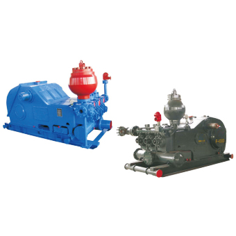
The 2,200-hp mud pump for offshore applications is a single-acting reciprocating triplex mud pump designed for high fluid flow rates, even at low operating speeds, and with a long stroke design. These features reduce the number of load reversals in critical components and increase the life of fluid end parts.
The pump’s critical components are strategically placed to make maintenance and inspection far easier and safer. The two-piece, quick-release piston rod lets you remove the piston without disturbing the liner, minimizing downtime when you’re replacing fluid parts.

Mickan Tool and Supply stocks API 7F Certified oilfield roller chain that is designed to resist wear and fatigue for longer life.Oil & gas roller chain applications for drawworks, mud pumps, transmission drives, catshafts, and rotary countershafts.Mickan Tool and Supply offers standard 10 foot box length and can also cut roller chain to exact pitch size.Mickan Tool and Supply also stocks common roller chain connecting links and offset links.
We stock API 7F certified oilfield roller chain, which has superior fatigue and shock load resistance providing maximum performance and reliability. If you are operating or repairing drawworks, mud pumps, catshafts, or countershafts, we can supply the best roller chain and roller chain parts to meet your requirement.

If you ended up on this page doing normal allowed operations, please contact our support at support@mdpi.com. Please include what you were doing when this page came up and the Ray ID & Your IP found at the

Gardner Denver, Lewco, NOV, Oilwell, National, Varco, Woolley, Baash-Ross, Demco, Bomco, Oteco, Brown & Sharpe, Ideco, P-Quip, and Continental Emsco, and the product models referenced on this website are trademarks or registered trademarks of their respective companies. Premium Oilfield Technologies is not authorized by or affiliated with any of these companies, and no business relationship, affiliation, or endorsement is claimed or implied.

Our state-of-the-art repair facilities combine world-class equipment with over 150 years of industry leading expertise, to provide our customers with a comprehensive range of services. If you can’t come to us, we can bring our legendary expertise to you, using our full range of on-site repair and field service offerings.

A mud pump (sometimes referred to as a mud drilling pump or drilling mud pump), is a reciprocating piston/plunger pump designed to circulate drilling fluid under high pressure (up to 7,500 psi or 52,000 kPa) down the drill string and back up the annulus. A mud pump is an important part of the equipment used for oil well drilling.
Mud pumps can be divided into single-acting pump and double-acting pump according to the completion times of the suction and drainage acting in one cycle of the piston"s reciprocating motion.
Mud pumps come in a variety of sizes and configurations but for the typical petroleum drilling rig, the triplex (three piston/plunger) mud pump is used. Duplex mud pumps (two piston/plungers) have generally been replaced by the triplex pump, but are still common in developing countries. Two later developments are the hex pump with six vertical pistons/plungers, and various quintuplexes with five horizontal piston/plungers. The advantages that these new pumps have over convention triplex pumps is a lower mud noise which assists with better measurement while drilling (MWD) and logging while drilling (LWD) decoding.
The fluid end produces the pumping process with valves, pistons, and liners. Because these components are high-wear items, modern pumps are designed to allow quick replacement of these parts.
To reduce severe vibration caused by the pumping process, these pumps incorporate both a suction and discharge pulsation dampener. These are connected to the inlet and outlet of the fluid end.
Displacement is calculated as discharged liters per minute. It is related to the drilling hole diameter and the return speed of drilling fluid from the bottom of the hole, i.e. the larger the diameter of drilling hole, the larger the desired displacement. The return speed of drilling fluid should wash away the debris and rock powder cut by the drill from the bottom of the hole in a timely manner, and reliably carry them to the earth"s surface. When drilling geological core, the speed is generally in range of 0.4 to 1.0 m^3/min.
The pressure of the pump depends on the depth of the drilling hole, the resistance of flushing fluid (drilling fluid) through the channel, as well as the nature of the conveying drilling fluid. The deeper the drilling hole and the greater the pipeline resistance, the higher the pressure needed.
With the changes of drilling hole diameter and depth, the displacement of the pump can be adjusted accordingly. In the mud pump mechanism, the gearbox or hydraulic motor is equipped to adjust its speed and displacement. In order to accurately measure the changes in pressure and displacement, a flow meter and pressure gauge are installed in the mud pump.
The construction department should have a special maintenance worker that is responsible for the maintenance and repair of the machine. Mud pumps and other mechanical equipment should be inspected and maintained on a scheduled and timely basis to find and address problems ahead of time, in order to avoid unscheduled shutdown. The worker should attend to the size of the sediment particles; if large particles are found, the mud pump parts should be checked frequently for wear, to see if they need to be repaired or replaced. The wearing parts for mud pumps include pump casing, bearings, impeller, piston, liner, etc. Advanced anti-wear measures should be adopted to increase the service life of the wearing parts, which can reduce the investment cost of the project, and improve production efficiency. At the same time, wearing parts and other mud pump parts should be repaired rather than replaced when possible.

A Mud Pump may have many changeable parts, such as liner, piston, extension rod, pulsation dampener, valve, clamp, etc. Lake Petro could provide 100% interchangeable parts of many common brands of pump. We offer Liners with Ceramic (Zirconia and Aluminium oxide) and Steel (Metal and Bi-metal) materials. Piston assembly is the important spare parts and expendable parts of oil drilling mud pumps. Mud pump valve assy include valve body, valve seat, valve insert (valve rubber ). Pulsation Dampener is usually installed on the discharge line to reduce the fluctuation of pressure and displacement of the drilling mud pump. Fluid End Module is an important component of the hydraulic pump end of the mud pump.

The first documented spring-pole well in America was drilled in 1806 by David and Joseph Ruffner in West Virginia. It reached 58 feet in depth, containing 40 feet of bedrock. The project lasted two years.
A patent to L. Disbrow for the first four-legged derrick was given, originally in 1825 and then elaborated on in 1830. The structure consisted of legs made of square timber wood. The girts were mortised and inserted into the wooden legs with keys so the structure could be dismantled.
Men in Kentucky were drilling an exploratory well for salt brine. Instead, they hit an oil well. The pressure of the gas and oil underneath the surface forced an enormous geyser into the air. This was noted to be America’s first oil well (although there are some disputes to this claim).
J.J. Couch invented the first mechanical percussion drill, which he later perfected with the help of fellow inventor J.W. Fowle. Steam was admitted alternately to each end of a cylinder. The drill was thrown like a lance at the rock on the forward stroke, caught and then drawn back on the reverse stroke, and then thrown again. It was the first drill that did not depend on gravity. It went to work on the Hoosac Tunnel project, which bored a passage for trains through hills near North Adams, Mass.
George Bissell and Edwin L. Drake made the first successful use of a drilling rig on a commercial well drilled especially to produce oil in Pennsylvania. They drilled to 69 feet.
In June, J.C. Rathbone drilled a discovery well to 140 feet using a steam engine on the banks of the Great Kanawha River in the Charleston, W.Va., area. The well produced about 100 barrels of oil a day.
Charles Burleigh, John W. Brooks, and Stephen F. Gates patented a mechanical drill meant to be used on the Hoosac tunnel: the compressed air Burleigh drill. The tunnel spurred several innovations in drilling technology, including the earlier Couch/Fowle drill.
Edward A.L. Roberts was awarded a patent in November 1866 for what would become known as the Roberts Torpedo, a device for increasing the flow of oil by using an explosion deep in a well. The new technology revolutionized the young oil and natural gas industry by increasing production from individual wells.
Simon Ingersoll received a patent for a rock drill on a tripod mount. The drill was designed for mining and tunneling. It enabled the operator to drill at virtually any angle. He formed Ingersoll Rock Drill to capitalize on this invention, a company that is a precursor to Ingersoll-Rand.
The Bucyrus Foundry and Manufacturing Company was founded in Bucyrus, Ohio. The company later became famous in the drilling industry as Bucyrus-Erie, a maker of cable-tool rigs, but it was an early producer of steam shovels. It supplied many of the steam shovels used in the building of the Panama Canal.
Edmund J. Longyear drilled the first diamond core hole in the Mesabi Iron Range (shown above in 1903) in northern Minnesota. Shortly thereafter, he formed a contract diamond drilling company to serve the rapidly growing U.S. iron ore mining and steel industry.
John Smalley Campbell issued the first U.S. patent for the use of flexible shafts to rotate drilling bits. The patent was for dental applications, but was broad enough to cover larger scales, such as those used now in horizontal oil wells.
The Baker brothers were using their rotary method for oil well drilling in the Corsicana field of Navarro County, Texas. Their rig was powered by a mule.
Drillers at Spindletop, including brothers Curt and Al Hamill and Peck Byrd, noticed that muddied-up freshwater could help stabilize a formation and prevent borehole collapse. They started circulating it and drilling mud was born.
Captain Anthony F. Lucas at Spindletop began drilling with a steam-driven rotary rig and a double-pronged fishtail bit. The gusher at Spindletop lasted nine days and ushered in the first Texas oil boom.
Inspired by the success of Spindletop and what it meant for the future of oil drilling in Texas, Howard Hughes Sr. and Walter Sharp founded the Sharp-Hughes Tool Company. The Hughes name lives on today in the name of the company Baker-Hughes.
Edmund J. Longyear and John E. Hodge formed Longyear & Hodge, the manufacturing partnership that would eventually evolve into Boart Longyear. The company"s early drills were steam powered.
Howard Hughes Sr. and Walter Sharp introduced the Sharp-Hughes Rock Bit, which was nicknamed the "rock eater." It was suited for deep boring through medium and hard rock.
The Supreme Court of the United States ruled that Standard Oil, which at the time controlled more than 90 percent of U.S. production, was a monopoly and that the company must be broken up to create competition in the market.
Lee C. Moore patented a system that clamped and secured bracing to steel pipe legs to build a steel derrick. At that time, oil derricks were commonly wooden cable tool rigs.
The rotary table and kelly were first used. The primary function of the rotary table was to transmit torque to the drillstring via the kelly, a section of pipe with a square cross-section that slotted through a similar shape on the rotating table.
Hugh Roberts, working as a geologist for Edmund Longyear, designed a new form of technology called a core splitter, which divided cores into 3- – 5-inch lengths for better analysis. Drilling firms used Roberts"s core splitter as standard equipment.
Victor York and Walter G. Black of Standard Oil Company of California were granted a patent for driving the rotary table with a shaft. This innovation guaranteed the ongoing success of the rotary drilling method.
The first true horizontal oil well was drilled near Texon, Texas. By the early 1980s, with advancements in drilling motors and steering, the technology finally became widespread.
Cal Talc, A. J. Lynch and National Pigment Chemical merged to form Baroid Sales Company. The new company, founded to serve the growing market for products for hydraulic rotary drilling, is based in Los Angeles.
In June, the New York State Natural Gas Corporation abandoned a project after having drilled the world"s deepest cable-tool well to a depth of 11,145 feet. The well was located in Van Etten, N.Y. The project started five years earlier.
The first downhole drilling motors, or mud motors, were designed and manufactured by Dyna-Drill. The motor was based on the 1930 Moineau design for progressive cavity pumps.
General Electric Research Lab (GE) introduced a new synthetic material made of diamond grains sintered together with cobalt. This new material, Compax, could be made into various shapes and retained diamond’s natural property of extreme hardness, but not its weak cleavage planes. To make a cutter, a thin layer of the synthetic diamond material was deposited onto a disk-shaped tungsten carbide substrate so that the assembly, called a “compact,” could be attached to the bit. Bits with this kind of cutter are generically called PDC bits.
Teleco Oilfield Services Inc., together with the U.S. Department of Energy, introduced mud pulse telemetry, now a widely used method of transmitting measurement while drilling data to the surface. Commercialized in 1978, the technology had been under development since the late 1960s. Data transmitted by pulses, together with trigonometry, can give operators a three-dimensional plot of the well being drilled. Pulse telemetry improved on the slower process of wireline logging. Teleco was later acquired by Baker Hughes.
The Versa-Sonic drill rig was put into operation. Versa-Drill International Inc. and Bowser-Morner built this rig that incorporated Ray Roussy’s new sonic drill head. Roussy had worked to improve and perfect the technology over more than 20 years from original designs, which modified oscillators for drilling purposes. Sonic drills, like this one used by the Army Corps of Engineers, are now widely used for sampling.
Professors at Texas Tech University developed “zipper fracking,” which is when operators drill two wells side by side. The process allowed both wells to produce more oil and gas.

Ivamberg Navarro de Almeida Jr.1, Pedro Duarte Antunes1, Felipe Orlando Centeno Gonzalez1, Roberto Akira Yamachita1, Andreas Nascimento2, Jose Luiz Goncalves1
The paper addresses a literature review of the technologies used in the transmission of measuring and logging data during well drilling. It presents a discussion about efficiency in data density transmission and reliability, especially when it comes to software and automated tools. Initially, this paper analyzes the principle of the telemetry systems, considering the mud pulse telemetry, acoustic telemetry, electromagnetic telemetry and wired drill pipe telemetry. They were detailed highlighting information about functionality, data transmission and its linkage to supporting software. Focus is also given to details of the main advantages and disadvantages of each technology considering the influences of lithology, drilling fluid and formation fluids in the reliability and capacity of data transmission.
Overall in a drilling activity, since it concerns a combination of several systems and machineries together in which communication and right information transmission through a chain implies a very important role, one can consider that the probability of encountering petroleum accumulations are around 30% in general. For the development of an entire field, 10% - 20% of the cost can be related to the exploration phase, 50% to the development phase and the remaining 30% - 40% to the production phase and related logistics. And from this exploratory phase, 40% - 80% is specifically related to the drilling (4% - 16% of the total field cost). Thus, this summarized figures point out how the exploratory drilling activity itself may have an economical impact in the overall operation, making it necessary to have an “eye” down-hole in order to accurately drive and control operation away from unforeseen events. Moreover, as one of the universal using methods for transmitting information from down-hole to the surface, the different telemetry systems have allowed the industry to overcome these obstacles [1] [2] .
In this sense, this paper will initially verify and analyze the principle of the telemetry systems, considering the mud pulse telemetry, acoustic telemetry, electromagnetic telemetry and wired drill pipe telemetry. They were detailed in a sense to point out the idea behind each one of them, highlighting information about functionality, data transmission and its linkage to supporting software.
Further, technical articles were collected in order to have a better approach about the theory and practical applicability in the industry, accomplished by researching directly with the equipment manufacturers such as Schlumberger, Halliburton, Baker Hughes and National Oilwell Varco (NOV). The paper details the information and processes with focus on the following aspects: data transmission capacity, transmission speed, signal attenuation factors, reliability and applicability―defining at the end the best technology that may be applied for ultra-deep related operations.
The geological formations are typically not homogeneous and quite different. Each formation has unique properties that affects the transmission of electrical signals and which varies with the depth, spacing, and sequence of different types of geological layers, among others. The electrical properties of the drill-string also dynamically vary with length, constitution of the drilling fluid and temperature.
In this context, the electromagnetic telemetry adapts to the electrical environment encountered in the well by means of a microprocessor in a monitoring tool, which continuously scans the frequency spectrum with electromagnetic signals to determine the optimum frequency for data transmission between the tools and processing units (computers) on the surface. This transmission can be achieved by both through the drill-string body or through the formation being drilled. Figure 1 shows a general electromagnetic telemetry system.
By determining the relative attenuation of the transmitted signal, the operator at the surface can send a command back to the tool (or vice-versa) to replace the frequency of the carrier wave with one that may suffer less attenuation and which may have a better signal to noise ratio. For example, highly resistive formations below the drill-string cannot function as ground and the drill-string itself must then be treated as a vertical dipole. In this case, the most effective frequency for the carrier wave would be one resonant with the drill-string, identified by the tool as the one drawing maximum input current. The most frequently used optimal selection technique is one in which the receiver periodically sends recognition signals to the transmitter, so that when this signal is not captured by the same transmitter, it changes the carrier wave frequency gradually decreasing it until it returns capturing the recognition signals from the receptor. However, by lowering the frequency of the carrier wave, the amount of transmitted data is consequently diminished. In this case the tool in the well has to be programmed to transmit only the most critical information relevant to the operation [4] .
The first papers on electromagnetic telemetry were quite promising, claiming that rates of up to 100 bits per second (bps) could be achieved with the use of signal repeaters. However, the development of mud pulse telemetry in parallel on the market brought more efficient results, with higher data transmission rates reaching greater depths, without the needs of repeaters usage. The huge attenuation suffered by the electromagnetic signals, caused by the formation properties, drilling mud and surface conditions led to a decline of this technology. Another aspect restricting this technology is the water. Due to its high electrical conductivity, it limits the use of electromagnetic telemetry in offshore operations with large water depths, making it to be relegated just to the oil & gas (O&G) market onshore and for shallow depths, considering the low transmission rates (SCHNITGER, 2009). On the other hand, in activities where usual drilling mud may not be used, alternatives are to use aerated
fluid or foams. In these specific cases, it is preferable to have electromagnetic since it allows a better transmission rate in comparison to mud pulses, but even, it is limited to approximately 9000 [ft.] depth.
The acoustic telemetry system is operated with batteries and is distinguished from other systems since it works by generating acoustic waves capable of transmitting real-time data to the surface through the walls of pipes at distances up to 12,000 [ft.]. A variety of data can be acquired and transmitted: pressure, temperature, time, command and information about the system status. This telemetry system is used mainly in exploratory wells and also for well-testing operations. Meters equipped with quartz crystal sensors located just above the tester valve generate accurate signals of temperature and pressure in the deep end, being stored in recording memory or directly transmitted to the surface. Each quartz sensor is able to store up to 440,000 readings in its memory, and the entire system is capable of storing more than 1.3 million scans, allowing great flexibility.
In real-time, the transmitter sends packets of data with all information acquired in every two minutes directly to the next repeater. A packet is a group 12 acoustically transmitted data sets, each set containing pressure information, temperature and time for sample intervals of 10 seconds. The repeater then forwards the packet to the surface to be decoded. The system is able to communicate in both directions, allowing the operator to send additional commands on the surface below to the system, for example, if any changes have to be done. Figure 2 exemplifies the acoustic telemetry system.
In wells deeper than 12,000 [ft], more repeaters are necessary but is not as straight forward as it looks like due to the “cross talk” problem (unwanted interference of a transmission channel to another). Moreover, in such environment the great difficulty lies in transmitting the acoustic signals to the surface through the docking column, which due to its size and components can cause large attenuation. Therefore, the acoustic signal is brought up to the sub transducer surface, and from there converted into an electrical signal and transmitted through a twisted pair cable to the surface. In 2011, XACT Downhole Telemetry Inc. published a study on its acoustic telemetry module capable of transmitting data to a 20 [bps] rate in wells up to 2500 [m] [7] .
This technology employs a module that modulates resistance to the flow of the drilling fluid through the inside of the drill-string, generating an increase and decrease of the stand-pipe pressure and so the mud pressure pulses representative of the parameters measured by the logging tools and that is propagated, approximately, at the speed of sound to surface. Transducers located on the surface detect and convert the pressure signal into a digital electrical signal through analog/digital (A/D) converters. This signal is then sent to a computer that will process and decode the signal received through specific and developed software to recognize and treat these signals [8] [9] .
detected by transducers, but, however, the pressure of the drilling fluid undergoes significant fluctuations and containing noises from various sources such as the drill noise, noise from the torque and from the mud pumps itself, etc. The drill noise is caused by its vibration during the drilling operation, which partially restricts the output of drilling fluid causing a high-frequency noise. Torque noise is caused by the increase in drill string torque when the drill is in contact with the formation; after contact, the torque in the column is relieved generating a peak of large amplitude and low frequency pressure. Finally, mud pump noises are due to the cyclical piston movement for displacing mud into the circulating system.
Some drilling systems use a buffer on the surface to reduce noise caused by the mud pump, but the pulsation dampener can also be adjusted for that. However, while they absorb some of the pressure fluctuations, they also act as a mirror, reflecting pressure pulses back to the telemetry module, sometimes destructively, creating interference and hindering or making the detection of pulses by the transducer in surface more difficult. A basic telemetry module contains two sections: one for communication and other for control of the generated pulses. The various logging tools send their data to the digital signal processor (DSP) located in the communication section. The processor operates according to software stored in memory in order to convert the data as a digital signal. A compression module reduces the amount of data transmitted over techniques involving the removal of certain data. It is also used differential encoding which allows a data string to be represented with fewer or less bits than usual (Emmerich, 2015).
The multiplexing module selects the data of the different tools and assembles a single chain of data being transmitted, divided into blocks that can contain information about synchronization and error correction. A coding module then converts the digital signal channels to be transmitted on a set of timings that are communicated to the pulse control section for generating them. The pulse control section consists of a processor, memory, an opening coil, closing coil, two banks of capacitors and battery. The control pulses operate a valve through the opening and closing coils generating the pressure pulses. The coils drain relatively high amounts of current in operation, in some cases more than the battery can deliver. Its power though must be within the operating capacity of the battery. To solve the problem of the current supply, each reel is associated with a capacitor bank. The battery charges the capacitors between the operations of the reels, and when the processor activates the reels they unload supplying current making the valve operation possible [8] [9] .
The valve that creates pressure pulses can have different shapes and constructions, being classified among different types in terms of operating system. The three most common used types are: positive pulse (Figure 3(a)), negative pulse (Figure 3(b)) and continuous pulse (Figure 3(c)). Any one of three types can be used provided that the valve can produce variations quickly enough (in the order of [ms]). The duration of the pulses may vary from 80 [ms] until approximately 400 [ms], depending on the drilling system parameters (Honório, 2007). In the positive pulse, the equipment creates a restriction in which the stand-pipe pressure increases. In the negative
one, the equipment allows part of the flow to leak to the annulus, creating a pressure decrease. Finally, in the continuous one, there is a modulator and a stator creating restrictions and reliefs continuously.
In 2008, Baker Hughes INTEQ published an article [10] suggesting major changes in conventional mud pulse telemetry systems. These changes included the use of an oscillating shear valve rather than rotational, capable of generating pressure pulses at the appropriate frequency for the well conditions and the use of two pressure transducers on the surface, rather than just one. The movement of this new valve had considerable impact on signal quality sent from down-hole, to the extent that it eliminates the time necessary to accelerate/decelerate the rotational valve during a frequency change for generating the bits, having the frequency exchanged instantaneously. This is a considerable advantage, since the whole bandwidth could be used for data transmission. Figure 4 illustrates this improvement.
Another important change was the use of calibration routines which were capable of monitoring the well conditions and automatically updating the data processing algorithm according to the current condition, improving process efficiency. These changes were tested in several critical wells around the world achieving an increase in data transfer-rate of approximately 200% with a 40 [bps] rate deep up to 24,000 [ft.].
This technology uses individually modified drill-pipes to provide a two-way telemetry system for real-time transmission, speeding up to 57,000 [bps], making possible to obtain large amounts of data from down-hole (Bybee, 2008). The technology uses high strength coaxial cables and low-loss inductive coils built in connections on each tubular joint to transmit information. Signal repeaters are placed at specific locations along the drill-string to ensure an acceptable signal to noise ratio. These repeaters operate as individually accessible nodes within the telemetry network, and thus, being able to identify sites that can provide potentially valuable measuring data. Figure 5 shows a schematic of the mentioned wired drill pipe, focusing on its threads.
A bi-directional network architecture, which is this specific case, allows the transmission of downhole data to the surface at high speed while commands can still be sent from the surface to the equipment itself. By inserting a physical and electrical interface, existing logging-while-drilling (LWD) and measuring-while-drilling (MWD) tools become fully compatible. Although there are small variations between tools from each manufacturer, the interfaces are generally consistent in the industry: it involves a network inductive connection at the top, a suitable electromechanical coupling on the bottom, a network card, modem and a power source.
For each technology, from different manufacturers data were obtained, as well as case studies, and recent articles that could be representative of what"s latest in a given technology were also combined resulting in a critical understanding. The electromagnetic telemetry is represented by Halliburton’s system―Sperry Drilling’s EMT [13] ; the acoustic telemetry by Acoustic Telemetry System (ATS) from Halliburton [5] ; the mud pulses telemetry by the TeleSCOPE system integrated with Orion II platform [11] , both from Schlumberger; and finally, the wired-drill-pipe telemetry represented by IntelliServ Network system [14] from National Oilwell Varco. Table 1 compares the telemetry systems in means of transmission rate, maximum reached depth, amount of data transmitted and technology cost.
Analyzing Table 1, it can be noticed that for ultra-deep wells with depths greater than 6000 [m], the electromagnetic and acoustic telemetry technologies are not applicable due to the depth restriction caused by the large attenuation of the signal in these conditions. Even by using signal repeaters, these technologies would be limited by 18,000 [ft.].
However, mud pulses telemetry and wired-drill-pipes follow technologically, advancing and increasingly hitting depth records with very efficient transmission rates. It is remarkable the huge difference between the ability to transmit data of these technologies, but this difference is mitigated by the high cost of wired-drill-pipes. Due to the fact that the cost of this system is directly proportional to the depth of the well, its application should be
restricted to high-valuable wells with return already guaranteed, which is not the case of exploratory wells. Thus, some attention is driven to the telemetry system based in mud pulses as the most feasible one in general, enabling acquisition of essential information with reasonable transmission rates.
The drilling activities in ultra-deep require profiling data telemetry technology that is both efficient and inexpensive, whereas in exploratory wells, field’s production potential may not yet be determined in its totality. It is important to note that telemetry technology for wired-drill-pipe despite being extremely efficient from a technical point of view, has a high cost of installation and maintenance. Currently, mainly due to the oil market crisis, a consequence of the oil price droopiness, it is extremely important to cut spending.
In this sense, telemetry technology through drilling mud pulses is still the leader due to the low-cost implicit in this technology, with well depths reaching above than others. By reinventing itself in the recent decades, it is now able to achieve high transmission rates with higher data density. The idea is then to develop new data compression algorithms and processing and signal modulation techniques allowing a way ahead for greater depth, enabling an efficient profiling with high cost effectiveness.
The authors acknowledge the financial support of Brazilian National Petroleum Agency (ANP) by means of Human Resource Program for the oil and gas sector (PRH).
Pedro DuarteAntunes,Felipe Orlando CentenoGonzalez,Roberto AkiraYamachita,AndreasNascimento,Jose LuizGoncalves,Ivamberg Navarro de AlmeidaJr., (2015) A Review of Telemetry Data Transmission in Unconventional Petroleum Environments Focused on Information Density and Reliability. Journal of Software Engineering and Applications,08,455-462. doi: 10.4236/jsea.2015.89043
1. Nascimento, A. and Nogueira, L.A.H. (2010) Exploração de petróleo em camadas do Pré-sal no Brasil: Um estudo de caso no Poço 1-SPS-50. Master Thesis, Universidade Federal de Itajubá, Instituto de Sistemas Elétricos e Energia, Itajubá.
4. Schnitger, J. and Macpherson, J. (2009) Signal Attenuation for Electromagnetic Telemetry Systems. SPE/IADC Drilling Conference and Exhibition, Amsterdam, 17-19 March 2009.
6. Harper, G., Almanza, E., Fossa, A., Finley, D. and Srang, E.G. (2003) Acoustic Telemetry System Provides Real-Time Data Acquisition. Proceedings of Offshore Technology Conference, Houston, 5-8 May 2003.
7. Neff, J.M. and Camwell, P.L. (2007) Field-Test Results of an Acoustic MWD System. IADC/SPE Drilling Conference, Amsterdam, 20-22 February 2007. http://dx.doi.org/10.2118/105021-ms
8. Emmerich, W., Akimov, O., Brahim, I.B. and Greten, E.A. (2015) Reliable High-Speed Mud Pulse Telemetry. IADC/ SPE Drilling Conference, London, 17-19 March 2015.
9. Honório, M.C. and Bortoni, E.C. (2007) Qualidade dos Dados Transmitidos Durante a Perfuração de Poços de Petróleo. Master Thesis, Universidade Federal de Itajubá, Instituto de Sistemas Elétricos e Energia, Itajuba.
10. Klotz, C., Bond, P. and Wasserman, I. (2008) A New Mud-Pulse Telemetry System for Enhanced MWD/LWD Applications. IADC/SPE Drilling Conference, Orlando, 4-6 March 2008.

Fossil fuels—oil, natural gas, and coal—are made of the preserved organic remains of ancient organisms. Organic matter is only preserved when its rate of accumulation is higher than the rate of its decay. This most often happens when the oxygen supply is so low that aerobic bacteria (oxygen-loving bacteria) cannot thrive, which greatly slows the breakdown of organic matter. When organic matter does not break down, over time it will be incorporated into buried sediment. After burial, the organic material is compacted and heated with the rest of the rock, eventually transforming it into fossil fuels.
A chunk of peat. Peat is an accumulation of partially decayed plant matter. Under proper heat and pressure, it will turn into lignite coal over geologic periods of time.Photo by Donna Beaver Pizzarella, USGS (public domain).
Oil and natural gas form from organic matter in the pores of sediments subjected to heat and pressure. The organic matter is primarily composed of photosynthetic plankton that die and sink to the bottom of large water bodies in vast numbers. Shale in particular is often organic rich, because organic matter settles and accumulates in the same places that mud (clay and silt particles) settles out of the water.
In most environments, organic matter is recycled by bacteria before it can be buried, but the quiet waters where mud accumulates are often relatively stagnant and low in oxygen. In these places, the bacterial decay rate is low relative to the rate at which organic matter sinks and becomes buried in muddy sediments. Under such conditions, organic matter may accumulate enough to make up several percent or more of the deposited sediment.
Oil and gas that form in rocks under the Earth"s surface are under pressure. Therefore, they will move gradually upward to areas of lower pressure through tiny connections between pore spaces and natural fractures in rocks.
A rock layer that forms a reservoir for oil or gas must be permeable. Fluids and gas (such as water, oil, and natural gas) can move through permeable rocks, or rocks that have enough connected fractures or space between grains to form pathways for the movement of fluids and gas. Sandstone, limestone, and fractured rocks are generally permeable.
Diagram of an oil and gas reservoir. In this image, natural gas and fluids (water and oil) have accumulated in a layer of permeable reservoir rock, where they are separated by density (gas is lightest, water densest). An impermeable clay or shale layer that has been folded serves as a barrier to further movement of fluids and gas upward toward the surface. Image modified from original by Jim Houghton, published in The Teacher-Friendly Guide to the Geology of the Southeastern U.S., 2nd ed., edited by Andrielle N. Swaby, Mark D. Lucas, and Robert M. Ross (published by the Paleontological Research Institution) (CC BY-NC-SA 4.0 license).
Oil shale is rock that contains an immature, waxy, solid organic material known as kerogen. Kerogen is not actually oil. Kerogen must be artificially heated to convert it into synthetic oil or a hydrocarbon gas. Thus, the whole rock layer, which may or may not technically be shale, must be mined and/or processed (possibly in place) to produce synthetic oil.
Rock salt (the mineral halite) is solid and impermeable, but when it is under very high pressure it can flow like a thick liquid. When a layer of salt is buried under thousands of feet of overlying sediment, it will start to deform. Because it is less dense than the rocks above it, it flows upward toward areas of lower pressure, forming geological structures named for their shapes (e.g., domes, canopies, tables, and lenses).
As salt structures grow, they in turn influence the topography of the surrounding landscape, creating zones of uplift surrounding areas of subsidence (sinking), fractures, and faults. When salt flows upward, it deforms the surrounding strata, creating gaps in which oil and gas may pool and be trapped. Oil and gas also accumulate under and along the salt structures.
Diagram of solution mining to create a salt cavern. A pumphouse pumps water into an underground salt dome. The water dissolves the salt, and the brine (salty water) is pumped back out, creating a salt cavern (a large cavity) in the salt dome. Image modified from original by Wade Greenberg-Brand, published in The Teacher-Friendly Guide to the Geology of the Southeastern U.S., 2nd ed., edited by Andrielle N. Swaby, Mark D. Lucas, and Robert M. Ross (published by the Paleontological Research Institution) (CC BY-NC-SA 4.0 license).
Natural asphalt seeps (tar pits) in California. Left:Bubbles in a tar pit in La Brea, Los Angeles, California. Photo by Daniel Schwen (Wikimedia Commons, Creative Commons Attribution license 2.5 Generic license, image cropped). Right:Asphalt seep in Carpinteria, Califronia. Photo by Ipab (Wikimedia Commons, Creative Commons Attribution-Share Alike 4.0 International license, image cropped and resized).
Once an oil trap or reservoir rock has been detected on land, oil crews excavate a broad, flat pit for equipment and supplies around the area where the well will be drilled. Once the initial hole is prepared, an apparatus called a drilling rig is set up. The rig is a complex piece of machinery designed to drill through rock to a predetermined depth. A typical drilling rig usually contains generators to power the system, motors and hoists to lift the rotary drill, and circulation systems to remove rock from the borehole and lubricate the drill bit with mud.
Diagrams of oil wells. Left:A conventional vertical well. Right:A horizontal well. Hydraulic fracturing may be carried out along horizontal wells running for 1.6 kilometers (1 mile) or more along layers with oil or gas trapped in pore spaces. Image modified from original by Jim Houghton, published in The Teacher-Friendly Guide to the Geology of the Southeastern U.S., 2nd ed., edited by Andrielle N. Swaby, Mark D. Lucas, and Robert M. Ross (published by the Paleontological Research Institution) (CC BY-NC-SA 4.0 license).
The support structure used to hold the drilling apparatus is called a derrick. In the early days of oil exploration, drilling rigs were semi-permanent structures and derricks were left onsite after the wells were completed. Today, however, most rigs are mobile and can be moved from well to well. Once the well has been drilled to a depth just above the oil reservoir, a cement casing is poured into the well to structurally reinforce it. Once the casing is set and sealed, oil is then allowed to flow into the well, the rig is removed, and production equipment can be put in place to extract the oil.
Devonian Solsville Shale Member, Marcellus Shale Formation, New York. The Marcellus Shale is a gas-producing shale that occurs primarily in New York, Ohio, Pennsylvania, and West Virginia. It is exploited for gas in some regions using hydraulic fracturing. Photo by James St. John (flickr, Creative Commons Attribution 2.0 Generic license, image cropped and resized).
Hydraulic fracturing uses horizontal wells drilled along the source rock layer. Most horizontal wells are drilled where the source rock is about 100–150 meters (330–490 feet) thick. The source rocks are fractured using high volumes of fracking fluid (frac fluid) flushed through the well at high pressure. The frac fluid is made up of water mixed with gel, sand, and chemicals. The gel increases the viscosity of the fluid. The thousands of tiny fractures created by the fluid are held open by the small grains of sand.
Hydraulic fracturing in progress in the Marcellus Shale of Pennsylvania. The Marcellus Shale is a Devonian-aged, gas-producing shale that occurs primarily in New York, Ohio, Pennsylvania, and West Virginia. Photo by Doug Duncan, USGS (public domain).
Fracking has been controversial, in large part because of associated impacts. For example, fracking and other oil and gas extraction activities create large quantities of wastewater that contain salts and other contaminants. This wastewater may include frac fluid and produced water. Produced water is water that is pumped out of the ground along with oil or gas. This contaminated water must be treated, reused, or contained.
Original description from the USGS: "House damage in central Oklahoma from the magnitude 5.6 earthquake on Nov. 6, 2011. Research conducted by USGS geophysicist Elizabeth Cochran and her university-based colleagues suggests that this earthquake was induced by injection into deep disposal wells in the Wilzetta North field." Photo by Brian Sherrod, USGS.
Coal ultimately comes from organic matter from land plants. Leaves, wood, and other plant matter accumulate on the ground as plants die or shed parts. If these structures do not rapidly decay, they may form peat, an accumulation of partially decayed plant matter. The peat may then be buried by additional organic matter and sediment. As the peat is buried more and more deeply by additional layers of sediment and organic matter, pressure from the overlying sediments builds, squeezing and compressing the peat into coal.
Stages in the formation of coal, from left to right: Peat is buried beneath a swamp. Through compaction and loss of water, it forms lignite. Through further compression, the coal transforms into bituminous coal and finally anthracite coal. Image modified from original by Jim Houghton, published in The Teacher-Friendly Guide to the Geology of the Southeastern U.S., 2nd ed., edited by Andrielle N. Swaby, Mark D. Lucas, and Robert M. Ross (published by the Paleontological Research Institution) (CC BY-NC-SA 4.0 license).
Coal deposits and the ages of coals in the contiguous US. The Tertiary period is the former name for the time interval now split into the Paleogene and Neogene periods. Source: USGS Open-File Report 96-92, digital compilation by John Tully.
Thick coal deposits are not found in coastal deposits and deltas that formed during earlier times even though geologic and climatic conditions were similar. This is because the plants that made up the coastal swamp forests that produced enough biomass to form large peat deposits had not yet evolved. Plants had only just begun to spread on to land and evolve vascular tissue during the Silurian period. Diversification and evolution of plants during the Devonian was rapid. As forests evolved and increased in size in the late Devonian and Carboniferous, significant quantities of organic matter were produced on land for the first time. The Carboniferous is not the only time period during which large coal deposits formed. Coals are also known from the Mesozoic and Cenozoic eras.
Dave Johnston Power Plant, a coal-fired power plant in Wyoming, photographed in 2006. Photo by Greg Goebel (flickr, Creative Commons Attribute-ShareAlike 2.0 Generic).
The Smith Mine in Montana was one of many coal mines where a mining disaster occurred during the 20th century in the US. The Smith Mining disaster happened on February 27, 1943, when methane in the mine ignited, causing an explosion. Ultimately, 74 men died from injuries caused by the explosion or suffocation due to toxic gases in the mine. Left:The abandoned mine. Photo by Tumbleweed 1954 (Wikimedia Commons, Creative Commons Attribution-Share Alike 4.0 International license, image cropped and resized). Right:Informational sign about the Smith Mine Disaster. Photo by Velela (Wikimedia Commons, public domain).
Methods have been developed to trap coalbed methane so that it can be used as an energy source. Water saturates fractures in some coal seams, making these seams aquifers. (An aquifer is a water-bearing, permeable rock formation that is capable of providing water in usable amounts to springs or wells.) If there is sufficient water pressure in a coal seam aquifer, methane within the coal fractures may be trapped in the coal. To extract coalbed methane, water is removed from the coal using a well. Removing water reduces the water pressure in the coal, allowing the trapped methane to escape. The gas moves out of the coal towards areas of lower pressure. As the methane moves into the well, it is separated from the water and captured.
After water is removed from a coal seam aquifer, it may take years for the aquifer to recharge (refill with water). The water in the aquifer will be slowly replenished by rain that falls at the surface and gradually works its way below the surface and to the aquifer.
The use of a well to relieve water pressure in a coal seam, allowing the methane to escape. As water is pumped out of the coal seam, the water pressure is lowered, allowing gas to escape. The gas is captured in a separate pipe as in bubbles up in the water at the bottom of the well. Diagram from "Fossil energy research benefits: Coalbed methane" US Department of Energy Office of Fossil Energy.
Triplex plunger-type mud pumps feature a reciprocating, positive displacement pump design utilizing three plungers to safely transfer high-viscosity fluids under high pressure over an extended depth. Although they have many industrial applications, these pumps have become an essential part of oil well drilling rigs where they’re used to provide smooth discharge of mud and debris from oil wells.
In addition to their use in drilling and well service operations, mud pumps are also frequently used to handle corrosive or abrasive fluids, as well as slurries containing relatively large particulates, in applications like commercial car washes, wastewater treatment, cementing, and desalination operations.
DAC Worldwide’s Representative Triplex, Plunger Mud Pump Dissectible (295-418) is an economical, conveniently-sized triplex plunger-type mud pump assembly that teaches learners hands-on maintenance activities commonly required on larger mud pump assemblies used in upstream oilfield production operations.
For example, mud pump assembly is used on well sites maintain downhole backpressure, to lubricate the rotating drill bit, and to help recycle and remove rock debris resulting from drilling activities. These heavy-duty, high-pressure pumps require regular refurbishment, inspection, and repair in the field.
DAC Worldwide’s dissectible mud pump assembly is a realistic sample that’s similar in geometry, design, and operating characteristics to the larger varieties learners will encounter on the job. DAC Worldwide chooses popular name-brand pumps for its dissectibles to ensure industrial and oil and gas training relevancy.
Using the dissectible mud pump, learners will gain hands-on experience with the operating principles, regular maintenance activities, and nomenclature/parts identification at a more convenient scale in the classroom or lab.
Technical training is most effective when learners can gain hands-on practice with industry-standard components they’ll encounter on the job. The Representative Triplex, Plunger Mud Pump Dissectible features a wide variety of common, industrial-quality components to provide learners with a realistic training experience that will build skills that translate easily to the workplace.
The Representative Triplex, Plunger Mud Pump Dissectible is a sturdy unit with a complete triplex, reciprocating, 20+ bhp plunger pump with .75" plunger, 1.5" stroke, and 3" cylinder sleeve. The unit allows for complete disassembly, assembly, and inspection, including removal of plungers, packing, and valves.
The dissectible mud pump comes with a formed-steel, powder-coated baseplate. It can also be mounted on a compatible DAC Worldwide Extended Electromechanical Workstation (903). Each unit comes with the manufacturer’s installation and maintenance manual.


 8613371530291