
creative commons mud pump oil and gas quotation

If you ended up on this page doing normal allowed operations, please contact our support at support@mdpi.com. Please include what you were doing when this page came up and the Ray ID & Your IP found at the
Electronic Pump Stroke Counters are a vital part to any drilling rig operation. When a mud pump is in operation, the driller must know how much mud is flowing down hole in order to keep the operation running at peak efficiency. Pump stroke counters assist the driller by measuring the mud pump’s strokes per minute and total strokes. So, how does a pump stroke counter tally the mud pump’s strokes
Electronic Pump Stroke Counters are a vital part to any drilling rig operation. When a mud pump is in operation, the driller must know how much mud is flowing down hole in order to keep the operation running at peak efficiency. Pump stroke counters assist the driller by measuring the mud pump’s strokes per minute and total strokes. So, how does a pump stroke counter tally the mud pump’s strokes, and why it is important? In order to understand that, you’ll need to know some basic information about mud pumps.
Knowing how a mud pump functions is important in understanding the role a pump stroke counter plays in rig operations. Mud pumps act as the heart of the drilling rig, similar to how our heart works. Just as our heart circulates blood throughout our bodies, a mud pump circulates essential drilling mud down the hole and back up to the surface. Mud tanks house drilling mud, and a mud pump draws the fluid from the mud pump. A piston draws mud in on the backstroke through the open intake valve and pushes mud through the discharge valve and sends it towards the rig. By circulating fluid, the mud pump ensures that the drill bit is cool and lubricated and that cuttings are flushed from the hole. The two main kinds of pumps used are duplex and triplex pumps, where the duplex pump has two pistons and the triplex pump has three. Whether the rig is using a duplex or triplex pump, it is important to know how many strokes per second the pistons are moving. The driller monitors strokes per minute to determine how much costly, yet essential, mud is being pumped into the system with the use of a mud pump stroke counter system. Now, that you know about mud pumps, you’ll need to know what’s in a stroke counter system.
Stroke Counter — The stroke counter stainless steel box is mounted on the driller’s console and is either square or rectangular in shape, depending on the number of pumps it is monitoring. Stroke counters will show strokes per minute and total strokes, and when a particular mud pump is operating the strokes/minute and total strokes will be displayed. Power is supplied by a 3.6 volt lithium battery, and the counter contains a crystal-controlled real time clock with 100 parts per million accuracy or better. Each counter is mounted to the console with 1/4” stainless steel hex head bolts, lock washers and nuts.
Micro Limit Switch — The micro switch is connected to a c clamp near the mud pump piston. The micro switch stainless steel rod (sometimes called a whisker) sticks out in the piston housing near the piston. As the piston passes the rod, it moves the rod and the switch sends an electronic signal back to the counter. The counter increases by one each time the piston moves the rod, counting the mud pump’s strokes. The switch’s signal is then transmitted to the stroke counter. These micro switches are built to stand up to demanding outdoor conditions. They can withstand shock, equipment vibration, extreme temperatures, water and dust.
Cable and Junction Box – A cable is connected to the back of the pump stroke counter and then to the junction box. From the junction box, the cables travel to the limit switches.
Pump Stroke Counters are like a blood pressure machine. Each time our heart pumps, a blood pressure machine reads our systolic and diastolic blood pressure by way of our pulse. A mud pump stroke counter functions in much the same way. Just as a blood pressure machine detects our pulse so too does a limit switch rod detect the movement of the piston. When the stainless steel rod is moved, the micro limit switch detects the movement. The signal is sensed as a contact closure, and it is transmitted to the stroke counter where the contact closure is converted to a logic pulse. The pulse feeds two separate circuits. The total strokes circuit reads and displays the closures one at a time, totaling them up to reveal the total strokes in the LED window. The second pulse is sent along a separate circuit which is a rate circuit. This rate circuit will average the closures against the real time clock. The result is displayed as the total strokes per minute.
Pump stroke counters are essential to drilling rig operations because they measure the efficiency of mud pumps. Knowing strokes per minute and total strokes of the pistons helps the driller to determine if the correct amount of mud is going down hole. Having this information aids in running a drilling rig at peak efficiency, assists in extending drill bit life, and avoids costly overuse of drilling rig mud. Unsure which pump stroke counter is right for your application? Give our friendly, knowledgeable staff a call or email. We’ll keep you turning right.
The circulation system on the rig is the system that allows for circulation of the Drilling Fluid or Mud down through the hollow drill string and up through the annular space between the drill string and wellbore. It is a continuous system of pumps, distribution lines, storage tanks, storage pits, and cleansing units that allows the drilling fluid to fulfill its primary objectives (these will be discussed later in this lesson). The mud pumps of the circulation system and the drawworks of the hoisting systems are the two largest draws on the power from the power system
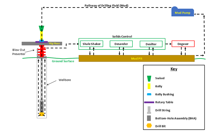
Drilling fluid is mixed in the mud pits and pumped by the mud pumps through the swivel, through the blow out preventer (not part of the circulation system) down the hollow drill pipe, through holes (Jet Nozzles) in the bit, up the annular space between drill pipe and wellbore (where it lifts the rock cuttings), to the surface, through the Solids Control Equipment (Shale Shaker, Desander, and Desilter), and back to the mud pits. A schematic of the circulation system is shown in Figure 9.05.
In this figure, fresh water-based drilling fluid (mud) is mixed with water from the Water Tank (not shown in Figure 9.05) and components from the Bulk Mud Components Storage (not shown in Figure 9.05) in the Mud Pit. The Mud Pumps then pump the mud through the swivel, kelly, kelly bushing, and rotary table down to the drill string.
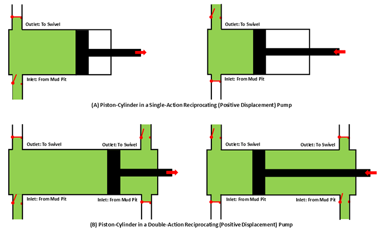
The mud pumps on a typical drilling rig are either single-action or double-action Reciprocating (Positive Displacement) Pumps which may contain two pistons-cylinders (duplex pump) or three pistons-cylinders (triplex pump). Figure 9.06 shows schematics of a single piston-cylinder in (A) a single-action and (B) a double-action reciprocating pump.
In these pumps, the positive pressure and negative pressure (suction) in the cylinder cause the valves to open and close (note: the valves in the schematic are simple representations of the actual valves). Due to the high viscosity of the drilling fluid, the inlet side of the pump may require a Charge Pump to keep fluids moving into the cylinders at high pressures and to prevent Cavitation in the pump.
From the mud pumps, the drilling fluid goes to the swivel, through the blow out preventer, and down the hollow drill string and bottom-hole assembly. The drilling fluid then goes through jet nozzles in the drill bit; at which point, it begins its return to the surface. The drilling fluid travels up the annular space between the drill pipe and the wellbore, picking up and carrying the drill cuttings up the hole.
Once the drilling fluid reaches the surface, it goes through the mud return line to the gas-mud separator and the solids control equipment. The shale shaker is where the large cuttings from the returning drilling fluid are removed. The shale shaker is a set of vibrating mesh screens that allow the mud to pass through while filtering out cuttings of different size at screen screen mesh sizes. A Mudlogger or a Well-Site Geologist may be stationed at the shale shaker to analyze the cuttings to determine the lithology of the rock and the depth within the Stratigraphic Column at which the well is currently being drilled.
The drilling fluid then passes through the Desander and Desilter. These are hydrocyclones which use centrifugal forces to separate the smaller solids from the drilling fluid. The desander typically removes solids with a diameter in the range of 45 – 74 μm, while the desilter removes solids with a diameter in the range of 15 – 44 μm.
The drilling fluid is then sent through a degasser to remove any gas bubbles that have been picked up during the circulation. These gasses may include natural gas from the subsurface or air acquired during the solids control. Typically, the degasser is a piece of equipment that subjects the drilling fluid to slight vacuum to cause the gas to expand for extraction. The drilling fluid is then returned to the mud pit to start the circulation process over again.
We have discussed the mechanics of how the drilling fluid is circulated during the drilling process, but we have not discussed the role of the drilling fluid. The term “mud” is often used in oil and gas well drilling because historically the most common water-based drilling fluids were mixtures of water and finely ground, bentonite clays which, in fact, are muds.
control formation pore pressures to assure desired well control (apply hydrostatic and hydrodynamic pressures in excess of the formation pore pressures to prevent fluids from entering the wellbore);
allow for pressure signals from Logging While Drilling (LWD) or Measurement While Drilling (MWD) tools to be transmitted to the surface (LWD and MWD data are transmitted to the surface using pressure pulses in the drilling fluid);
As I stated earlier, historically drilling fluids were mixtures of bentonite clay, water, and certain additives to manipulate the properties of the mud (density, viscosity, fluid loss properties, gelling qualities, etc.). Today, there are several different options available for drilling fluids. These include:
Of the listed drilling fluids, the water-based muds and the oil-based muds are the most common; foam drilling and air drilling can only be used under specialized conditions. Of the two liquid based mud systems (water-based muds and oil-based muds), water-based muds are the most common mud system. They are more environmentally friendly and are used almost exclusively to drill the shallow portions of the well where fresh water aquifers exist to minimize any contamination to those aquifers. As this implies, drilling fluids can be – and often are – switched during the course of drilling operations in single well.
In addition, water-based muds are cheaper than oil-based muds, so they are used to reduce drilling costs and commonly represent the “default” selection for a drilling fluid. In other words, water-based muds are often used unless there is a specific reason to switch to an oil-based mud.
Oil-based muds are formulated with diesel oil, mineral oil, or synthetic oils as a continuous phase and water as a dispersed phase in an emulsion. In addition, additives such as emulsifiers and gelling agents are also used. They were specifically developed to address certain drilling problems encountered with water-based muds. The reasons for using an oil-based mud include:
drilling through shales that are susceptible to swelling (in particular, highly smectite-rich shales). Shales contain a large amount of clay material and when these clays come in contact with the water in a water-based mud system, the clays may swell causing the shales to collapse into the hole. Smectite-rich shale formations are often referred to as “Gumbo” or “Gumbo Clays” in the drilling industry;
reducing torque and drag problems in deviated wells. Since oil, a lubricant, is the continuous phase in the mud system, the torque and drag between the drill pipe and the wellbore is reduced with oil-based muds;
achieving greater thermal stability at greater depths. Oil-based muds have been found to retain their stability (retain their desired properties) at greater down hole temperatures;
achieving greater resistance to chemical contamination. Many substances found down-hole (salt, CO2, H2S, etc.) are soluble in water. The introduction of these substances into the water-based mud system may have a deleterious impact on different mud properties (density, viscosity, fluid loss properties, gelling properties, etc.). These substances are not soluble in oil and, therefore, have will not impact oil-based mud properties.
The first three bullet points in this list are becoming more common problems in the oil and gas industry. The shale boom in the U.S. has made long horizontal sections in shale reservoirs targets for drilling. In addition, deviated wells and deeper wells are also becoming more common. For these reasons, the use of oil-based muds is also becoming more common.
high initial costs. Often in an active drilling campaign, if certain depth intervals require an oil-based mud, the mud is stored and reused in different wells;
slow rates of penetration. Historically, the rate of penetration has been statistically slower for oil-based muds than it is for water-based muds. The rate of penetration is the speed at which the drilling process progresses (depth versus time) and is a function of many factors other than mud type, including: weight on bit, RPM, lithologies being drilled through, bit type, bit wear, etc.;
kick detection. If gas enters the wellbore (a Kick), it may go into solution in the oil in deeper, higher pressure sections of the well and come out of solution closer to the surface;
formation evaluation. Some readings from well logs or core analysis may be sensitive to oil entering the formation of interest (for example, if oil from the oil-based mud enters the reservoir in the near-well vicinity, then tools used to detect oil saturation may read artificially high).
Other drilling fluids currently in use that were listed earlier are foams and air. In the context of drilling fluids, foams have the consistency of shaving cream. Both foam and air drilling are used in hard rock regions, such as in the Rocky Mountains, where drill bits render the drill cuttings to dust. Thus, the foam or air only needs to lift this dust to the surface. Air drilling is always an environmentally friendly option if it is applicable because environmental contamination by air is never an issue.
Researchers have shown that mud pulse telemetry technologies have gained exploration and drilling application advantages by providing cost-effective real-time data transmission in closed-loop drilling operations. Given the inherited mud pulse operation difficulties, there have been numerous communication channel efforts to improve data rate speed and transmission distance in LWD operations. As discussed in “MPT systems signal impairments”, mud pulse signal pulse transmissions are subjected to mud pump noise signals, signal attenuation and dispersion, downhole random (electrical) noises, signal echoes and reflections, drillstring rock formation and gas effects, that demand complex surface signal detection and extraction processes. A number of enhanced signal processing techniques and methods to signal coding and decoding, data compression, noise cancellation and channel equalization have led to improved MPT performance in tests and field applications. This section discusses signal-processing techniques to minimize or eliminate signal impairments on mud pulse telemetry system.
At early stages of mud pulse telemetry applications, matched filter demonstrated the ability to detect mud pulse signals in the presence of simulated or real noise. Matched filter method eliminated the mud noise effects by calculating the self-correlation coefficients of received signal mixed with noise (Marsh et al. 1988). Sharp cutoff low-pass filter was proposed to remove mud pump high frequencies and improve surface signal detection. However, matched filter method was appropriate only for limited single frequency signal modulated by frequency-shift keying (FSK) with low transmission efficiency and could not work for frequency band signals modulated by phase shift keying (PSK) (Shen et al. 2013a).
Wavelet transform method was developed and widely adopted and used in signal processing to overcome limitation of Fourier transform in time domain (Bultheel 2003). Although Fourier and its revised fast Fourier transforms are powerful mathematical tool, they are not very good at detecting rapid changes in signals such as seismic data and well test data in petroleum industry containing many structure of different scales (Multi-scale structures) (Guan et al. 2004). Fourier coefficients do not provide direct information about the signal local behavior (localization); but the average strength of that frequency in the full signal as the sine or cosine function keeps undulating to infinity. Wavelet transform analyzes the signal frequency components and time segment, and fine tune sampling of localized characters of time or frequency domain. Principles of wavelet transform and de-noising technique show that signal can be divided into space and scale (time and frequency) without losing any useful information of the original signal, hence ensuring the extraction of useful information from the noised signal (Li et al. 2007). Different wavelet base parameters constructed, such as haar, db, coif, sym, bior, rbio and dmey, are suitable for different signal processing requirements. The small the scale parameter is, the higher the resolving power in frequency, suitable for processing high frequency signals; conversely, the larger the scale is the higher resolving power suitable for low frequency signal.
In processing noise-contaminated mud pulse signals, longer vanishing moments are used, but takes longer time for wavelet transform. The main wavelet transform method challenges include effective selection of wavelet base, scale parameters and vanishing moment; the key determinants of signal correlation coefficients used to evaluate similarities between original and processed signals. Chen et al. (2010) researched on wavelet transform and de-noising technique to obtain mud pulse signals waveform shaping and signal extraction based on the pulse-code information processing to restore pulse signal and improve SNR. Simulated discrete wavelet transform showed effective de-noise technique, downhole signal was recovered and decoded with low error rate. Namuq et al. (2013) studied mud pulse signal detection and characterization technique of non-stationary continuous pressure pulses generated by the mud siren based on the continuous Morlet wavelet transformation. In this method, generated non-stationary sinusoidal pressure pulses with varying amplitudes and frequencies used ASK and FSK modulation schemes. Simulated wavelet technique showed appropriate results for dynamic signal characteristics analysis.
While Fourier coefficients provide average signal information in frequency domain and unable to reveal the non-stationary signal characteristics, wavelet transform can effectively eliminate MPT random noise when signal carrier frequency characteristics (periods, frequencies, and start and end time) are carefully analyzed.
As discussed in “MPT mud pump noises”, the often overlap of the mud pulses frequency spectra with the mud pump noise frequency components adds complexity to mud pulse signal detection and extraction. Real-time monitoring requirement and the non-stationary frequency characteristics made the utilization of traditional noise filtering techniques very difficult (Brandon et al. 1999). The MPT operations practical problem contains spurious frequency peaks or outliers that the standard filter design cannot effectively eliminate without the possibility of destroying some data. Therefore, to separate noise components from signal components, new filtering algorithms are compulsory.
Early development Brandon et al. (1999) proposed adaptive compensation method that use non-linear digital gain and signal averaging in the reference channel to eliminate the noise components in the primary channel. In this method, synthesized mud pulse signal and mud pump noise were generated and tested to examine the real-time digital adaptive compensation applicability. However, the method was not successfully applied due to complex noise signals where the power and the phases of the pump noises are not the same.
Jianhui et al. (2007) researched the use of two-step filtering algorithms to eliminate mud pulse signal direct current (DC) noise components and attenuate the high frequency noises. In the study, the low-pass finite impulse response (FIR) filter design was used as the DC estimator to get a zero mean signal from the received pressure waveforms while the band-pass filter was used to eliminate out-of-band mud pump frequency components. This method used center-of-gravity technique to obtain mud pulse positions of downhole signal modulated by pulse positioning modulation (PPM) scheme. Later Zhao et al. (2009) used the average filtering algorithm to decay DC noise components and a windowed limited impulse response (FIR) algorithm deployed to filter high frequency noise. Yuan and Gong (2011) studied the use of directional difference filter and band-pass filter methods to remove noise on the continuous mud pulse differential binary phase shift keying (DBPSK) modulated downhole signal. In this technique, the directional difference filter was used to eliminate mud pump and reflection noise signals in time domain while band-pass filter isolated out-of-band noise frequencies in frequency domain.
Other researchers implemented adaptive FIR digital filter using least mean square (LMS) evaluation criterion to realize the filter performances to eliminate random noise frequencies and reconstruct mud pulse signals. This technique was adopted to reduce mud pump noise and improve surface received telemetry signal detection and reliability. However, the quality of reconstructed signal depends on the signal distortion factor, which relates to the filter step-size factor. Reasonably, chosen filter step-size factor reduces the signal distortion quality. Li and Reckmann (2009) research used the reference signal fundamental frequencies and simulated mud pump harmonic frequencies passed through the LMS filter design to adaptively track pump noises. This method reduced the pump noise signals by subtracting the pump noise approximation from the received telemetry signal. Shen et al. (2013a) studied the impacts of filter step-size on signal-to-noise ratio (SNR) distortions. The study used the LMS control algorithm to adjust the adaptive filter weight coefficients on mud pulse signal modulated by differential phase shift keying (DPSK). In this technique, the same filter step-size factor numerical calculations showed that the distortion factor of reconstructed mud pressure QPSK signal is smaller than that of the mud pressure DPSK signal.
Study on electromagnetic LWD receiver’s ability to extract weak signals from large amounts of well site noise using the adaptive LMS iterative algorithm was done by (Liu 2016). Though the method is complex and not straightforward to implement, successive LMS adaptive iterations produced the LMS filter output that converges to an acceptable harmonic pump noise approximation. Researchers’ experimental and simulated results show that the modified LMS algorithm has faster convergence speed, smaller steady state and lower excess mean square error. Studies have shown that adaptive FIR LMS noise cancellation algorithm is a feasible effective technique to recover useful surface-decoded signal with reasonable information quantity and low error rate.
Different techniques which utilize two pressure sensors have been proposed to reduce or eliminate mud pump noises and recover downhole telemetry signals. During mud pressure signal generation, activated pulsar provides an uplink signal at the downhole location and the at least two sensor measurements are used to estimate the mud channel transfer function (Reckmann 2008). The telemetry signal and the first signal (pressure signal or flow rate signal) are used to activate the pulsar and provide an uplink signal at the downhole location; second signal received at the surface detectors is processed to estimate the telemetry signal; a third signal responsive to the uplink signal at a location near the downhole location is measured (Brackel 2016; Brooks 2015; Reckmann 2008, 2014). The filtering process uses the time delay between first and third signals to estimate the two signal cross-correlation (Reckmann 2014). In this method, the derived filter estimates the transfer function of the communication channel between the pressure sensor locations proximate to the mud pump noise source signals. The digital pump stroke is used to generate pump noise signal source at a sampling rate that is less than the selected receiver signal (Brackel 2016). This technique is complex as it is difficult to estimate accurately the phase difference required to give quantifiable time delay between the pump sensor and pressure sensor signals.
As mud pulse frequencies coincide with pump noise frequency in the MPT 1–20 Hz frequency operations, applications of narrow-band filter cannot effectively eliminate pump noises. Shao et al. (2017) proposed continuous mud pulse signal extraction method using dual sensor differential signal algorithm; the signal was modulated by the binary frequency-shift keying (BFSK). Based on opposite propagation direction between the downhole mud pulses and pump noises, analysis of signal convolution and Fourier transform theory signal processing methods can cancel pump noise signals using Eqs. 3 and 4. The extracted mud pulse telemetry signal in frequency domain is given by Eqs. 3 and 4 and its inverse Fourier transformation by Eq. 4. The method is feasible to solve the problem of signal extraction from pump noise,
\(H(\omega )={f^{ - 1}}h(t)=G(\omega ){e^{ - j\omega \tau }}\) is the Fourier transformed impulse response, \(h(t)\), data transmission between sensor A and sensor B.
These researches provide a novel mud pulse signal detection and extraction techniques submerged into mud pump noise, attenuation, reflections, and other noise signals as it moves through the drilling mud.

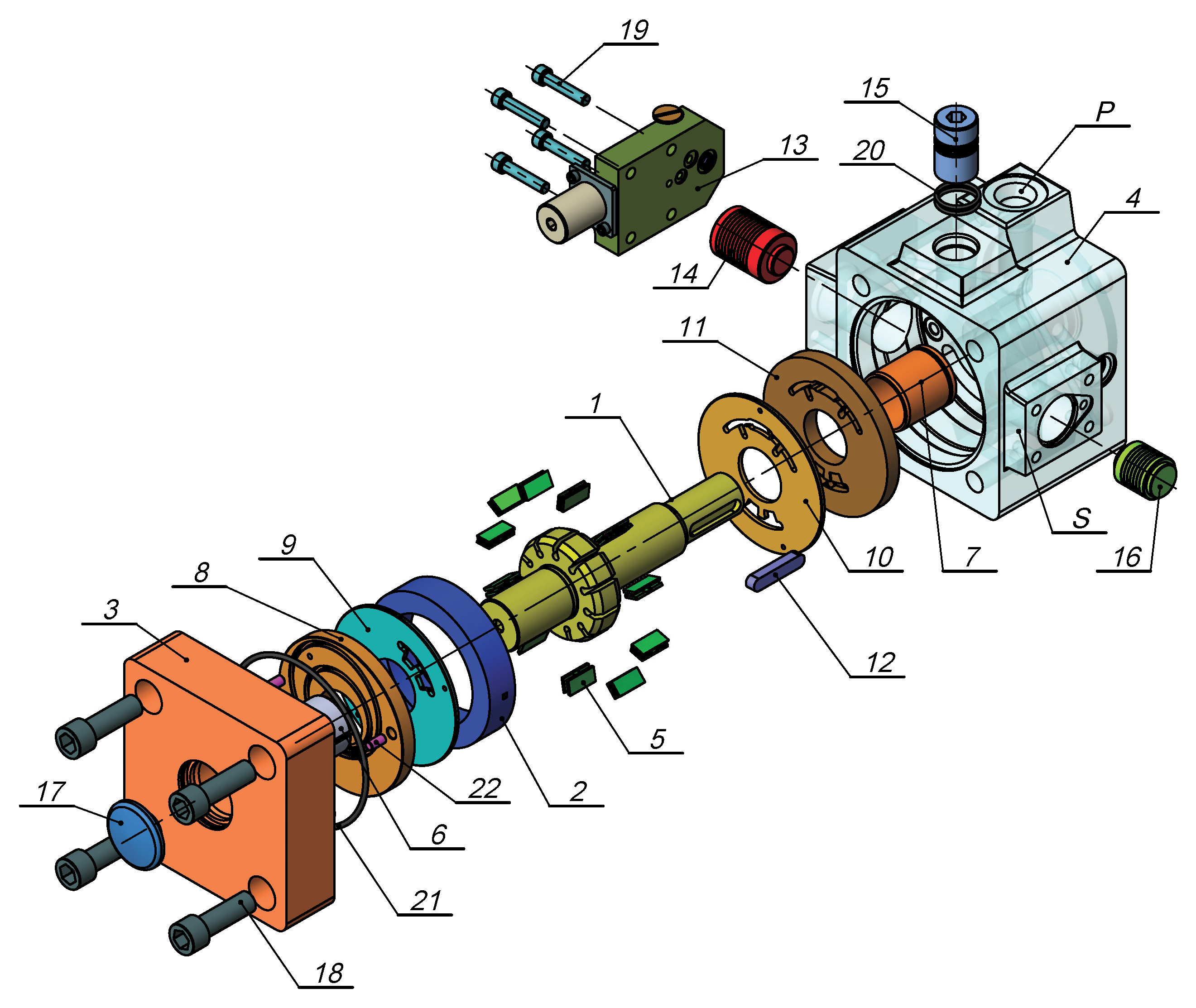
The 2,200-hp mud pump for offshore applications is a single-acting reciprocating triplex mud pump designed for high fluid flow rates, even at low operating speeds, and with a long stroke design. These features reduce the number of load reversals in critical components and increase the life of fluid end parts.
The pump’s critical components are strategically placed to make maintenance and inspection far easier and safer. The two-piece, quick-release piston rod lets you remove the piston without disturbing the liner, minimizing downtime when you’re replacing fluid parts.
Mickan Tool and Supply stocks API 7F Certified oilfield roller chain that is designed to resist wear and fatigue for longer life.Oil & gas roller chain applications for drawworks, mud pumps, transmission drives, catshafts, and rotary countershafts.Mickan Tool and Supply offers standard 10 foot box length and can also cut roller chain to exact pitch size.Mickan Tool and Supply also stocks common roller chain connecting links and offset links.
We stock API 7F certified oilfield roller chain, which has superior fatigue and shock load resistance providing maximum performance and reliability. If you are operating or repairing drawworks, mud pumps, catshafts, or countershafts, we can supply the best roller chain and roller chain parts to meet your requirement.
This website is using a security service to protect itself from online attacks. The action you just performed triggered the security solution. There are several actions that could trigger this block including submitting a certain word or phrase, a SQL command or malformed data.
HPHT well is defined as the well have bottom hole temperature exceeds 300oF and bottom hole pressure greater than 0.8 psi/ft. Nowadays, companies try to find petroleum in unconventional areas such as HPHT deep water, to decrease the gap between the demand and supply. Drilling of HPHT deep water wells involves high risk and cost; therefore, effective methods are required to solve these issues. Oil and gas industry offer advanced drilling technologies to reach HPHT deep water reservoir targets safely[1].
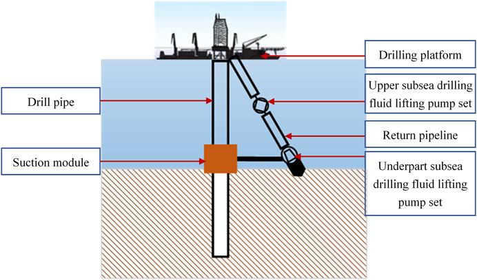
The margin between pore pressure and fracture pressure in HPHT deep water well is narrow, therefore accurate determination and optimization of well hydraulics is highly required. Managed Pressure Drilling (MPD) has been developed for overcoming the HPHT deep water well challenges. In MPD techniques, there is a method defined as Riser less drilling. The Riser less method uses two different annular fluid pressure gradients for well drilling. In the technique of Riser less drilling, the riser is completely filled with sea water and returned mud along with the cuttings is pumped by additional subsea mud pump to surface through small return line 6”,(Figure 1) [2].
There are pressure and temperature variations across wellbore during drilling by Riser less drilling technique; above seabed there is low temperature condition which will lead to increase in mud rheology, however below seabed there is opposite effect. Well hydraulics planning depends on how drilling fluid rheology is influenced by pressure and temperature effects inside wellbore; therefore, ignoring these effects in the well hydraulics calculations will give erroneous result[3].Accurate well hydraulics planning for HPHT wells is needed to avoid drilling problems such as kick and loss of circulation. This paper presents a new approach for accurate determination and optimization well hydraulics of MPD (Riser less drilling) under HPHT conditions. This work shows the comparison between well hydraulics calculated by constant fluid properties (i.e independent on pressure and temperature conditions) and well hydraulics calculated by taking into account the effect of pressure and temperature on fluid properties. This research also shows the effect of tool joint, cutting, annular eccentricity and drill string rotation pressure losses on well hydraulics of MPD.Theoretical Background
Temperature modelling, mud density and pressure modelling, plastic viscosity and yield point modelling and rheological hydraulic modelling are indeed important for accurate determination and optimization for well hydraulics of MPD under HPHT conditions.Drilling Fluid Temperature Modelling
Temperature modelling inside the wellbore is necessary for determining well hydraulics. Wellbore temperature has great impact on mud properties such as density, hydrostatic pressure, yield point and viscosity, therefore it will influence on the determination of pressure losses and Equivalent Circulating Density (ECD)[ 4].The Holmes and Swift model 5 assumes steady-state linear heat transfer between annulus fluid and the formation. The model is described in three steps[5].
Step 3: Calculation of temperature in drill pipe and annulus. For the temperature of the mud in the drill pipe and annulus (Equations 7, 8, 9, 10)[5].
Drilling fluid density is affected by temperature and pressure[6].The Hobe rock [7]Model assumes that drilling fluid density variations as a result of pressure and temperature changes occur due to liquid constituent’s volumetric behaviour such as water and/or oil.
Politte[8]studied rheological data for oil based mud and concluded that the plastic viscosity follows the base oil behaviour. Therefore, the plastic viscosity can be normalized with the base oil viscosity[9].The Politte[8]equation is described as follows.
Procedure of Politte correlation[8]can be used with any base oil. He established the following formula as a function of temperature and pressure for viscosity of base oil (Equation13) from analysis of diesel oil No. 2[8].
First two-parameter model is Power law model. The model is the most popular one in drilling engineering and it is used inside the simulator, Equation15[10].
Ivamberg Navarro de Almeida Jr.1, Pedro Duarte Antunes1, Felipe Orlando Centeno Gonzalez1, Roberto Akira Yamachita1, Andreas Nascimento2, Jose Luiz Goncalves1
The paper addresses a literature review of the technologies used in the transmission of measuring and logging data during well drilling. It presents a discussion about efficiency in data density transmission and reliability, especially when it comes to software and automated tools. Initially, this paper analyzes the principle of the telemetry systems, considering the mud pulse telemetry, acoustic telemetry, electromagnetic telemetry and wired drill pipe telemetry. They were detailed highlighting information about functionality, data transmission and its linkage to supporting software. Focus is also given to details of the main advantages and disadvantages of each technology considering the influences of lithology, drilling fluid and formation fluids in the reliability and capacity of data transmission.
Overall in a drilling activity, since it concerns a combination of several systems and machineries together in which communication and right information transmission through a chain implies a very important role, one can consider that the probability of encountering petroleum accumulations are around 30% in general. For the development of an entire field, 10% - 20% of the cost can be related to the exploration phase, 50% to the development phase and the remaining 30% - 40% to the production phase and related logistics. And from this exploratory phase, 40% - 80% is specifically related to the drilling (4% - 16% of the total field cost). Thus, this summarized figures point out how the exploratory drilling activity itself may have an economical impact in the overall operation, making it necessary to have an “eye” down-hole in order to accurately drive and control operation away from unforeseen events. Moreover, as one of the universal using methods for transmitting information from down-hole to the surface, the different telemetry systems have allowed the industry to overcome these obstacles [1] [2] .
In this sense, this paper will initially verify and analyze the principle of the telemetry systems, considering the mud pulse telemetry, acoustic telemetry, electromagnetic telemetry and wired drill pipe telemetry. They were detailed in a sense to point out the idea behind each one of them, highlighting information about functionality, data transmission and its linkage to supporting software.
Further, technical articles were collected in order to have a better approach about the theory and practical applicability in the industry, accomplished by researching directly with the equipment manufacturers such as Schlumberger, Halliburton, Baker Hughes and National Oilwell Varco (NOV). The paper details the information and processes with focus on the following aspects: data transmission capacity, transmission speed, signal attenuation factors, reliability and applicability―defining at the end the best technology that may be applied for ultra-deep related operations.
The geological formations are typically not homogeneous and quite different. Each formation has unique properties that affects the transmission of electrical signals and which varies with the depth, spacing, and sequence of different types of geological layers, among others. The electrical properties of the drill-string also dynamically vary with length, constitution of the drilling fluid and temperature.
In this context, the electromagnetic telemetry adapts to the electrical environment encountered in the well by means of a microprocessor in a monitoring tool, which continuously scans the frequency spectrum with electromagnetic signals to determine the optimum frequency for data transmission between the tools and processing units (computers) on the surface. This transmission can be achieved by both through the drill-string body or through the formation being drilled. Figure 1 shows a general electromagnetic telemetry system.
By determining the relative attenuation of the transmitted signal, the operator at the surface can send a command back to the tool (or vice-versa) to replace the frequency of the carrier wave with one that may suffer less attenuation and which may have a better signal to noise ratio. For example, highly resistive formations below the drill-string cannot function as ground and the drill-string itself must then be treated as a vertical dipole. In this case, the most effective frequency for the carrier wave would be one resonant with the drill-string, identified by the tool as the one drawing maximum input current. The most frequently used optimal selection technique is one in which the receiver periodically sends recognition signals to the transmitter, so that when this signal is not captured by the same transmitter, it changes the carrier wave frequency gradually decreasing it until it returns capturing the recognition signals from the receptor. However, by lowering the frequency of the carrier wave, the amount of transmitted data is consequently diminished. In this case the tool in the well has to be programmed to transmit only the most critical information relevant to the operation [4] .
The first papers on electromagnetic telemetry were quite promising, claiming that rates of up to 100 bits per second (bps) could be achieved with the use of signal repeaters. However, the development of mud pulse telemetry in parallel on the market brought more efficient results, with higher data transmission rates reaching greater depths, without the needs of repeaters usage. The huge attenuation suffered by the electromagnetic signals, caused by the formation properties, drilling mud and surface conditions led to a decline of this technology. Another aspect restricting this technology is the water. Due to its high electrical conductivity, it limits the use of electromagnetic telemetry in offshore operations with large water depths, making it to be relegated just to the oil & gas (O&G) market onshore and for shallow depths, considering the low transmission rates (SCHNITGER, 2009). On the other hand, in activities where usual drilling mud may not be used, alternatives are to use aerated
fluid or foams. In these specific cases, it is preferable to have electromagnetic since it allows a better transmission rate in comparison to mud pulses, but even, it is limited to approximately 9000 [ft.] depth.
The acoustic telemetry system is operated with batteries and is distinguished from other systems since it works by generating acoustic waves capable of transmitting real-time data to the surface through the walls of pipes at distances up to 12,000 [ft.]. A variety of data can be acquired and transmitted: pressure, temperature, time, command and information about the system status. This telemetry system is used mainly in exploratory wells and also for well-testing operations. Meters equipped with quartz crystal sensors located just above the tester valve generate accurate signals of temperature and pressure in the deep end, being stored in recording memory or directly transmitted to the surface. Each quartz sensor is able to store up to 440,000 readings in its memory, and the entire system is capable of storing more than 1.3 million scans, allowing great flexibility.
In real-time, the transmitter sends packets of data with all information acquired in every two minutes directly to the next repeater. A packet is a group 12 acoustically transmitted data sets, each set containing pressure information, temperature and time for sample intervals of 10 seconds. The repeater then forwards the packet to the surface to be decoded. The system is able to communicate in both directions, allowing the operator to send additional commands on the surface below to the system, for example, if any changes have to be done. Figure 2 exemplifies the acoustic telemetry system.
In wells deeper than 12,000 [ft], more repeaters are necessary but is not as straight forward as it looks like due to the “cross talk” problem (unwanted interference of a transmission channel to another). Moreover, in such environment the great difficulty lies in transmitting the acoustic signals to the surface through the docking column, which due to its size and components can cause large attenuation. Therefore, the acoustic signal is brought up to the sub transducer surface, and from there converted into an electrical signal and transmitted through a twisted pair cable to the surface. In 2011, XACT Downhole Telemetry Inc. published a study on its acoustic telemetry module capable of transmitting data to a 20 [bps] rate in wells up to 2500 [m] [7] .
This technology employs a module that modulates resistance to the flow of the drilling fluid through the inside of the drill-string, generating an increase and decrease of the stand-pipe pressure and so the mud pressure pulses representative of the parameters measured by the logging tools and that is propagated, approximately, at the speed of sound to surface. Transducers located on the surface detect and convert the pressure signal into a digital electrical signal through analog/digital (A/D) converters. This signal is then sent to a computer that will process and decode the signal received through specific and developed software to recognize and treat these signals [8] [9] .
detected by transducers, but, however, the pressure of the drilling fluid undergoes significant fluctuations and containing noises from various sources such as the drill noise, noise from the torque and from the mud pumps itself, etc. The drill noise is caused by its vibration during the drilling operation, which partially restricts the output of drilling fluid causing a high-frequency noise. Torque noise is caused by the increase in drill string torque when the drill is in contact with the formation; after contact, the torque in the column is relieved generating a peak of large amplitude and low frequency pressure. Finally, mud pump noises are due to the cyclical piston movement for displacing mud into the circulating system.
Some drilling systems use a buffer on the surface to reduce noise caused by the mud pump, but the pulsation dampener can also be adjusted for that. However, while they absorb some of the pressure fluctuations, they also act as a mirror, reflecting pressure pulses back to the telemetry module, sometimes destructively, creating interference and hindering or making the detection of pulses by the transducer in surface more difficult. A basic telemetry module contains two sections: one for communication and other for control of the generated pulses. The various logging tools send their data to the digital signal processor (DSP) located in the communication section. The processor operates according to software stored in memory in order to convert the data as a digital signal. A compression module reduces the amount of data transmitted over techniques involving the removal of certain data. It is also used differential encoding which allows a data string to be represented with fewer or less bits than usual (Emmerich, 2015).
The multiplexing module selects the data of the different tools and assembles a single chain of data being transmitted, divided into blocks that can contain information about synchronization and error correction. A coding module then converts the digital signal channels to be transmitted on a set of timings that are communicated to the pulse control section for generating them. The pulse control section consists of a processor, memory, an opening coil, closing coil, two banks of capacitors and battery. The control pulses operate a valve through the opening and closing coils generating the pressure pulses. The coils drain relatively high amounts of current in operation, in some cases more than the battery can deliver. Its power though must be within the operating capacity of the battery. To solve the problem of the current supply, each reel is associated with a capacitor bank. The battery charges the capacitors between the operations of the reels, and when the processor activates the reels they unload supplying current making the valve operation possible [8] [9] .
The valve that creates pressure pulses can have different shapes and constructions, being classified among different types in terms of operating system. The three most common used types are: positive pulse (Figure 3(a)), negative pulse (Figure 3(b)) and continuous pulse (Figure 3(c)). Any one of three types can be used provided that the valve can produce variations quickly enough (in the order of [ms]). The duration of the pulses may vary from 80 [ms] until approximately 400 [ms], depending on the drilling system parameters (Honório, 2007). In the positive pulse, the equipment creates a restriction in which the stand-pipe pressure increases. In the negative
one, the equipment allows part of the flow to leak to the annulus, creating a pressure decrease. Finally, in the continuous one, there is a modulator and a stator creating restrictions and reliefs continuously.
In 2008, Baker Hughes INTEQ published an article [10] suggesting major changes in conventional mud pulse telemetry systems. These changes included the use of an oscillating shear valve rather than rotational, capable of generating pressure pulses at the appropriate frequency for the well conditions and the use of two pressure transducers on the surface, rather than just one. The movement of this new valve had considerable impact on signal quality sent from down-hole, to the extent that it eliminates the time necessary to accelerate/decelerate the rotational valve during a frequency change for generating the bits, having the frequency exchanged instantaneously. This is a considerable advantage, since the whole bandwidth could be used for data transmission. Figure 4 illustrates this improvement.
Another important change was the use of calibration routines which were capable of monitoring the well conditions and automatically updating the data processing algorithm according to the current condition, improving process efficiency. These changes were tested in several critical wells around the world achieving an increase in data transfer-rate of approximately 200% with a 40 [bps] rate deep up to 24,000 [ft.].
This technology uses individually modified drill-pipes to provide a two-way telemetry system for real-time transmission, speeding up to 57,000 [bps], making possible to obtain large amounts of data from down-hole (Bybee, 2008). The technology uses high strength coaxial cables and low-loss inductive coils built in connections on each tubular joint to transmit information. Signal repeaters are placed at specific locations along the drill-string to ensure an acceptable signal to noise ratio. These repeaters operate as individually accessible nodes within the telemetry network, and thus, being able to identify sites that can provide potentially valuable measuring data. Figure 5 shows a schematic of the mentioned wired drill pipe, focusing on its threads.
A bi-directional network architecture, which is this specific case, allows the transmission of downhole data to the surface at high speed while commands can still be sent from the surface to the equipment itself. By inserting a physical and electrical interface, existing logging-while-drilling (LWD) and measuring-while-drilling (MWD) tools become fully compatible. Although there are small variations between tools from each manufacturer, the interfaces are generally consistent in the industry: it involves a network inductive connection at the top, a suitable electromechanical coupling on the bottom, a network card, modem and a power source.
For each technology, from different manufacturers data were obtained, as well as case studies, and recent articles that could be representative of what"s latest in a given technology were also combined resulting in a critical understanding. The electromagnetic telemetry is represented by Halliburton’s system―Sperry Drilling’s EMT [13] ; the acoustic telemetry by Acoustic Telemetry System (ATS) from Halliburton [5] ; the mud pulses telemetry by the TeleSCOPE system integrated with Orion II platform [11] , both from Schlumberger; and finally, the wired-drill-pipe telemetry represented by IntelliServ Network system [14] from National Oilwell Varco. Table 1 compares the telemetry systems in means of transmission rate, maximum reached depth, amount of data transmitted and technology cost.
Analyzing Table 1, it can be noticed that for ultra-deep wells with depths greater than 6000 [m], the electromagnetic and acoustic telemetry technologies are not applicable due to the depth restriction caused by the large attenuation of the signal in these conditions. Even by using signal repeaters, these technologies would be limited by 18,000 [ft.].
However, mud pulses telemetry and wired-drill-pipes follow technologically, advancing and increasingly hitting depth records with very efficient transmission rates. It is remarkable the huge difference between the ability to transmit data of these technologies, but this difference is mitigated by the high cost of wired-drill-pipes. Due to the fact that the cost of this system is directly proportional to the depth of the well, its application should be
restricted to high-valuable wells with return already guaranteed, which is not the case of exploratory wells. Thus, some attention is driven to the telemetry system based in mud pulses as the most feasible one in general, enabling acquisition of essential information with reasonable transmission rates.
The drilling activities in ultra-deep require profiling data telemetry technology that is both efficient and inexpensive, whereas in exploratory wells, field’s production potential may not yet be determined in its totality. It is important to note that telemetry technology for wired-drill-pipe despite being extremely efficient from a technical point of view, has a high cost of installation and maintenance. Currently, mainly due to the oil market crisis, a consequence of the oil price droopiness, it is extremely important to cut spending.
In this sense, telemetry technology through drilling mud pulses is still the leader due to the low-cost implicit in this technology, with well depths reaching above than others. By reinventing itself in the recent decades, it is now able to achieve high transmission rates with higher data density. The idea is then to develop new data compression algorithms and processing and signal modulation techniques allowing a way ahead for greater depth, enabling an efficient profiling with high cost effectiveness.
The authors acknowledge the financial support of Brazilian National Petroleum Agency (ANP) by means of Human Resource Program for the oil and gas sector (PRH).
Pedro DuarteAntunes,Felipe Orlando CentenoGonzalez,Roberto AkiraYamachita,AndreasNascimento,Jose LuizGoncalves,Ivamberg Navarro de AlmeidaJr., (2015) A Review of Telemetry Data Transmission in Unconventional Petroleum Environments Focused on Information Density and Reliability. Journal of Software Engineering and Applications,08,455-462. doi: 10.4236/jsea.2015.89043
1. Nascimento, A. and Nogueira, L.A.H. (2010) Exploração de petróleo em camadas do Pré-sal no Brasil: Um estudo de caso no Poço 1-SPS-50. Master Thesis, Universidade Federal de Itajubá, Instituto de Sistemas Elétricos e Energia, Itajubá.
4. Schnitger, J. and Macpherson, J. (2009) Signal Attenuation for Electromagnetic Telemetry Systems. SPE/IADC Drilling Conference and Exhibition, Amsterdam, 17-19 March 2009.
6. Harper, G., Almanza, E., Fossa, A., Finley, D. and Srang, E.G. (2003) Acoustic Telemetry System Provides Real-Time Data Acquisition. Proceedings of Offshore Technology Conference, Houston, 5-8 May 2003.
7. Neff, J.M. and Camwell, P.L. (2007) Field-Test Results of an Acoustic MWD System. IADC/SPE Drilling Conference, Amsterdam, 20-22 February 2007. http://dx.doi.org/10.2118/105021-ms
8. Emmerich, W., Akimov, O., Brahim, I.B. and Greten, E.A. (2015) Reliable High-Speed Mud Pulse Telemetry. IADC/ SPE Drilling Conference, London, 17-19 March 2015.
9. Honório, M.C. and Bortoni, E.C. (2007) Qualidade dos Dados Transmitidos Durante a Perfuração de Poços de Petróleo. Master Thesis, Universidade Federal de Itajubá, Instituto de Sistemas Elétricos e Energia, Itajuba.
10. Klotz, C., Bond, P. and Wasserman, I. (2008) A New Mud-Pulse Telemetry System for Enhanced MWD/LWD Applications. IADC/SPE Drilling Conference, Orlando, 4-6 March 2008.


 8613371530291