
diy well drilling mud pump free sample

There are many different ways to drill a domestic water well. One is what we call the “mud rotary” method. Whether or not this is the desired and/or best method for drilling your well is something more fully explained in this brief summary.
One advantage of drilling with compressed air is that it can tell you when you have encountered groundwater and gives you an indication how much water the borehole is producing. When drilling with water using the mud rotary method, the driller must rely on his interpretation of the borehole cuttings and any changes he can observe in the recirculating fluid. Mud rotary drillers can also use borehole geophysical tools to interpret which zones might be productive enough for your water well.
The mud rotary well drilling method is considered a closed-loop system. That is, the mud is cleaned of its cuttings and then is recirculated back down the borehole. Referring to this drilling method as “mud” is a misnomer, but it is one that has stuck with the industry for many years and most people understand what the term actually means.
The water is carefully mixed with a product that should not be called mud because it is a highly refined and formulated clay product—bentonite. It is added, mixed, and carefully monitored throughout the well drilling process.
The purpose of using a bentonite additive to the water is to form a thin film on the walls of the borehole to seal it and prevent water losses while drilling. This film also helps support the borehole wall from sluffing or caving in because of the hydraulic pressure of the bentonite mixture pressing against it. The objective of the fluid mixture is to carry cuttings from the bottom of the borehole up to the surface, where they drop out or are filtered out of the fluid, so it can be pumped back down the borehole again.
When using the mud rotary method, the driller must have a sump, a tank, or a small pond to hold a few thousand gallons of recirculating fluid. If they can’t dig sumps or small ponds, they must have a mud processing piece of equipment that mechanically screens and removes the sands and gravels from the mixture. This device is called a “shale shaker.”
The driller does not want to pump fine sand through the pump and back down the borehole. To avoid that, the shale shaker uses vibrating screens of various sizes and desanding cones to drop the sand out of the fluid as it flows through the shaker—so that the fluid can be used again.
When the borehole has reached the desired depth and there is evidence that the formation it has penetrated will yield enough water, then it’s time to make the borehole into a well.
Before the well casing and screens are lowered into the borehole, the recirculating fluid is slowly thinned out by adding fresh water as the fluid no longer needs to support sand and gravel. The driller will typically circulate the drilling from the bottom up the borehole while adding clear water to thin down the viscosity or thickness of the fluid. Once the fluid is sufficiently thinned, the casing and screens are installed and the annular space is gravel packed.
Gravel pack installed between the borehole walls and the outside of the well casing acts like a filter to keep sand out and maintain the borehole walls over time. During gravel packing of the well, the thin layer of bentonite clay that kept the borehole wall from leaking drilling fluid water out of the recirculating system now keeps the formation water from entering the well.
This is where well development is performed to remove the thin bentonite layer or “wall cake” that was left behind. Various methods are used to remove the wall cake and develop the well to its maximum productivity.
Some drillers use compressed air to blow off the well, starting at the first screened interval and slowly working their way to the bottom—blowing off all the water standing above the drill pipe and allowing it to recover, and repeating this until the water blown from the well is free of sand and relatively clean. If after repeated cycles of airlift pumping and recovery the driller cannot find any sand in the water, it is time to install a well development pump.
Additional development of the well can be done with a development pump that may be of a higher capacity than what the final installation pump will be. Just as with cycles of airlift pumping of the well, the development pump will be cycled at different flow rates until the maximum capacity of the well can be determined. If the development pump can be operated briefly at a flow rate 50% greater than the permanent pump, the well should not pump sand.
Mud rotary well drillers for decades have found ways to make this particular system work to drill and construct domestic water wells. In some areas, it’s the ideal method to use because of the geologic formations there, while other areas of the country favor air rotary methods.
Some drilling rigs are equipped to drill using either method, so the contractor must make the decision as to which method works best in your area, for your well, and at your point in time.
To learn more about the difference between mud rotary drilling and air rotary drilling, click the video below. The video is part of our “NGWA: Industry Connected” YouTube series:
Gary Hix is a Registered Professional Geologist in Arizona, specializing in hydrogeology. He was the 2019 William A. McEllhiney Distinguished Lecturer for The Groundwater Foundation. He is a former licensed water well drilling contractor and remains actively involved in the National Ground Water Association and Arizona Water Well Association.
To learn more about Gary’s work, go to In2Wells.com. His eBooks, “Domestic Water Wells in Arizona: A Guide for Realtors and Mortgage Lenders” and “Shared Water Wells in Arizona,” are available on Amazon.

Drilling a well by hand is a lot of work, but it can be done with the right equipment. Whether you’re looking to drill a shallow or deep well, this skill is perfect for those seeking self-reliance.
Wells are normally drilled on private land where city or rural water isn’t available. It’s possible to hire a licensed professional to provide this service but you can expect to spend several thousand dollars. If you want to save money, you can do it yourself, but prior to getting started, you need to research local regulations.
Each state or county will have its own list of requirements and regulations. These can be found online or at your county courthouse. When asking about these regulations, make sure you explain that you will be drilling the well yourself and on your own land.
The local courthouse may also have well drilling logs from professional well drillers. These will include things like when they hit first water, what type of soil condition they encountered, and how deep they drilled the well. This could be helpful information but do remember that every property is different. The very first step might be determining how deep you need to drill.
Things to consider when choosing a well location are: convenience, a power source, and location. It’s very important the well be uphill from any septic system or barn runoff.
The final thing to do before drilling is to contact utility companies to make sure you don’t hit any underground pipes or lines. Sometimes this information can be found on your original land plot, but it’s always good to double-check.
Drilling a shallow well is a pretty simple task, going down about 25 feet or so when you hit first water (at least in my location). This type of well could be drilled in a weekend by hand using a general purpose, extendable post-hole auger.
This type of well can be cased off with a manual pump and used for irrigation. This would be more of an emergency setup that could also provide water needs at a weekend cabin in the countryside.
Shallow wells have a difficult time keeping up with average water usage. It’s estimated each person uses between 80 and 100 gallons of water a day. Imagine storing 20, 5-gallon jugs a day per person.
The majority of our water usage comes from flushing toilets and bathing. If you multiply that by a family of four, it’s easy to understand you would need a deeper well to keep up with demand.
Professional well diggers will often recommend a depth of 200 feet or more, but remember, for hundreds of years every well in this country was hand-dug and that’s how people survived.
Also remember, licensed well diggers get paid by the foot, so sometimes they drill further than they have to. So, if you decide to hire this out, do your research and make sure to write down where first water is normally hit in your area. And keep in mind that first water may not be the best, can dry up in some years, or may not be able to keep up with demand; all of these things need to be considered.
A pneumatic drill is like a giant eggbeater driven by compressed air. This tool can drill a 200-foot well in a matter of days or weeks, depending on the soil type, and can be purchased online.
You can choose between, gas, diesel or electric-powered compressors. An electric compressor will cost you less to run and be more dependable. We chose a compressor powered by gas because our well project was several miles away from the homesite.
This brings us to the drill setup. This will require a day of planning before drilling begins. Most home improvement stores will carry almost everything you need.
Step 2: Dig a shallow settling pond 10 feet behind the well, no less than 4 feet across. Then dig a shallow 8-inch ditch connecting the pond to the well hole. Connect these spaces with 2-inch PVC pipe and cover. This pipe will transfer clean water from the pond to the drill hole. The pipe opening in the pond will need covering with netting so debris doesn’t flow back into the well.
Step 3: Insert the 55-gallon drum at the edge of the pond, secure with stakes, and face the opening toward the well. The drum catches water from the well and empties into the pond where clean water will flow from the pipe back into the well.
Step 4: Attach 1-inch PVC pipe to the pneumatic drill using PVC glue and secure with duct tape to prevent leaks. Use a marker every 5 to 10 feet so you can keep track of how far down you have drilled. Rest the other end of attached PVC pipe in the 55-gallon drum. While the drill is running, mud and water will enter the pipe through small holes above the drill and be pushed up by the compressed air, traveling through the pipe into the drum and settling pond to be cycled back into the well hole.
Step 5: The air compressor will need to be set up and connected to the drill. Use duct tape to secure the air hose to the PVC pipe to keep it out of the way while drilling.
Drilling a well with this tool can take anywhere from 15 hours to weeks depending on the soil type, so make sure a chair is handy and you’re working with at least three people. One to operate the compressor, another to drill, and a third for breaks.
The air supply to the drill should never be turned off while the drill is underwater. If this happens, you’ll have to stop drilling and clean the motor before starting back up. This can take time and delay progress, which means it’s important that your drill team understands the process from start to finish.
Begin by filling the well hole with water. Turn the drill on before inserting, and then begin drilling. The bit will drill through all soil types, but when it hits clay or rock the process will slow down. Don’t get frustrated, just keep drilling and, before you know it, first water will be hit.
Add the next several feet of pipe and start again. Once the desired depth is reached, it’s time to case off the well. Casing is a matter of inserting SDR 35 pipe and securing in place with pea gravel and concrete. To do so, drill a hole through both sidewalls of the first piece of pipe, 2 or 3 inches from the bottom so you can attach the rope to lower the pipe into the well. When the top of the pipe is even with the ground, apply PVC glue and attach the next piece of pipe. Let dry for 15 minutes and then continue to lower down and add pieces as you go to meet the depth of the well. The last piece of pipe will be cut about 3 feet above ground level and capped off.
Pour pea gravel between the casing and the dirt. Next, mix the concrete and pour between the ground and casing. This will prevent the well from becoming contaminated from runoff. Once this is complete and you’ve added a well pump, you’ll need to run the well for a couple of days until the water is clear, and it’s always a good idea to get the water tested before using it for drinking.
Drilling a well can be a long process, but if you can save money and learn a new skill at the same time, why not give it a try? It’s a matter of getting back to basics and doing more for yourself.

OK, all y’all air drillers just thumb on over to Porky’s column or something. This is for mud drillers. On second thought, I know a lot of you air guys drill about three mud wells a year, and consider it a hassle to rig up mud. So, maybe something I say will be interesting …
The mud pump is the heart of the circulating system, and mud is the blood circulating in the hole. I’ve talked about mud before and will again, but this month, let’s talk about the pump.
Historically, more wells, of every kind, have been drilled with duplex pumps than any other kind. They are simple and strong, and were designed in the days when things were meant to last. Most water well drillers use them. The drawbacks are size and weight. A pump big enough to do the job might be too big to fit on the rig, so some guys use skid-mounted pumps. They also take a fair amount of horsepower. If you were to break down the horsepower requirements of your rig, you would find out that the pump takes more power than the rotary and hoist combined. This is not a bad thing, since it does a lot of the work drilling. While duplex pumps generally make plenty of volume, one of the limiting factors is pressure. Handling the high pressures demanded by today’s oil well drilling required a pump so big and heavy as to be impractical. Some pretty smart guys came up with the triplex pump. It will pump the same — or more — volume in a smaller package, is easy to work on and will make insane pressure when needed. Some of the modern frack outfits run pumps that will pump all day long at 15,000 psi. Scary. Talk about burning some diesel.
The places that triplex pumps have in the shallow drilling market are in coring and air drilling. The volume needs are not as great. For instance, in hard rock coring, surface returns are not always even seen, and the fluid just keeps the diamonds cool. In air drilling, a small triplex is used to inject foam or other chemicals into the air line. It’s basically a glorified car wash pump. The generic name is Bean pump, but I think this just justifies a higher price. Kinda like getting the same burger at McDonald’s versus in a casino.
One of the reasons water well drillers don’t run triplex pumps, besides not needing insane pressure, is they require a positive suction head. In other words, they will not pick up out of the pit like a duplex. They require a centrifugal charging pump to feed them, and that is just another piece of equipment to haul and maintain.
This brings me to another thought: charging. I know a lot of drillers running duplex pumps that want to improve the efficiency of their pumps. Duplexes with a negative suction head generally run at about 85 percent efficiency. The easy way to improve the efficiency is to charge them, thus assuring a 100 percent efficiency. This works great, but almost every one of them, after doing all that work and rigging up a charging pump, tells me that their pump output doubled. Being the quiet, mild mannered type that I am, I don’t say “Bull,” but it is. A duplex pump is a positive displacement pump. That means that it can deliver no more than the displacement it was designed for. You can only fill the cylinder up until it is full. It won’t take any more. The one exception to this is when you are pumping at very low pressure. Then the charging pump will over run the duplex, float the valves and produce a lot more fluid. Might as well shut off the duplex and drill with the charging pump.
Another common pump used in the water well industry is the centrifugal. You see them mostly on air rigs that don’t use mud too often. They have their place, but are a different breed of cat. They are not positive displacement. Flow is a function of speed and horsepower up to the limits of the pump. After that, they just dead-head. With large diameter drill pipe they make a lot of mud, but after the hole gets deeper, friction losses — both inside and outside the drill pipe — build up. This means that the deeper you go, the less circulation you have. This slows the whole process. Positive displacement pumps don’t do this; they pump the same per stroke regardless of pressure. It just takes more horsepower. Also, displacement calculations like bottoms-up time and cement placement are just about impossible. One way to get around the limited pressure of centrifugal pumps is to run two of them in series. I’ve seen a few of these rig-ups and they work very well for large diameter drilling. They will make almost the same pressure as a big duplex for a lot less money. They are still variable displacement, but they roll so much fluid that it doesn’t seem to matter. And run at pretty reasonable depths, too: 300 to 400 psi at 400 gpm is not uncommon with two 3 x 4 centrifugal pumps in series.
I reckon there are pumps for every type of drilling. It is just a matter of using the right one correctly. I once drilled a 42-inch hole 842 feet deep with a 5½ x 8 duplex. Talk about long bottoms-up time … but we got the casing in with less than two feet of fill on bottom! Took time, but we got-er-done.

If you run a mud rig, you have probably figured out that the mud pump is the heart of the rig. Without it, drilling stops. Keeping your pump in good shape is key to productivity. There are some tricks I have learned over the years to keeping a pump running well.
First, you need a baseline to know how well your pump is doing. When it’s freshly rebuilt, it will be at the top efficiency. An easy way to establish this efficiency is to pump through an orifice at a known rate with a known fluid. When I rig up, I hook my water truck to my pump and pump through my mixing hopper at idle. My hopper has a ½-inch nozzle in it, so at idle I see about 80 psi on the pump when it’s fresh. Since I’m pumping clear water at a known rate, I do this on every job.
As time goes on and I drill more hole, and the pump wears, I start seeing a decrease in my initial pressure — 75, then 70, then 65, etc. This tells me I better order parts. Funny thing is, I don’t usually notice it when drilling. After all, I am running it a lot faster, and it’s hard to tell the difference in a few gallons a minute until it really goes south. This method has saved me quite a bit on parts over the years. When the swabs wear they start to leak. This bypass pushes mud around the swab, against the liners, greatly accelerating wear. By changing the swab at the first sign of bypass, I am able to get at least three sets of swabs before I have to change liners. This saves money.
Before I figured this out, I would sometimes have to run swabs to complete failure. (I was just a hand then, so it wasn’t my rig.) When I tore the pump down to put in swabs, lo-and-behold, the liners were cut so badly that they had to be changed too. That is false economy. Clean mud helps too. A desander will pay for itself in pump parts quicker than you think, and make a better hole to boot. Pump rods and packing last longer if they are washed and lubricated. In the oilfield, we use a petroleum-based lube, but that it not a good idea in the water well business. I generally use water and dish soap. Sometimes it tends to foam too much, so I add a few tablets of an over the counter, anti-gas product, like Di-Gel or Gas-Ex, to cut the foaming.
Maintenance on the gear end of your pump is important, too. Maintenance is WAY cheaper than repair. The first, and most important, thing is clean oil. On a duplex pump, there is a packing gland called an oil-stop on the gear end of the rod. This is often overlooked because the pump pumps just as well with a bad oil-stop. But as soon as the fluid end packing starts leaking, it pumps mud and abrasive sand into the gear end. This is a recipe for disaster. Eventually, all gear ends start knocking. The driller should notice this, and start planning. A lot of times, a driller will change the oil and go to a higher viscosity oil, thinking this will help cushion the knock. Wrong. Most smaller duplex pumps are splash lubricated. Thicker oil does not splash as well, and actually starves the bearings of lubrication and accelerates wear. I use 85W90 in my pumps. A thicker 90W140 weight wears them out a lot quicker. You can improve the “climbing” ability of the oil with an additive, like Lucas, if you want. That seems to help.
Outside the pump, but still an important part of the system, is the pop-off, or pressure relief valve. When you plug the bit, or your brother-in-law closes the discharge valve on a running pump, something has to give. Without a good, tested pop-off, the part that fails will be hard to fix, expensive and probably hurt somebody. Pop-off valve are easily overlooked. If you pump cement through your rig pump, it should be a standard part of the cleanup procedure. Remove the shear pin and wash through the valve. In the old days, these valves were made to use a common nail as the shear pin, but now nails come in so many grades that they are no longer a reliable tool. Rated shear pins are available for this. In no case should you ever run an Allen wrench! They are hardened steel and will hurt somebody or destroy your pump.
One last thing that helps pump maintenance is a good pulsation dampener. It should be close to the pump discharge, properly sized and drained after every job. Bet you never thought of that one. If your pump discharge goes straight to the standpipe, when you finish the job your standpipe is still full of fluid. Eventually the pulsation dampener will water-log and become useless. This is hard on the gear end of the pump. Open a valve that drains it at the end of every job. It’ll make your pump run smoother and longer.
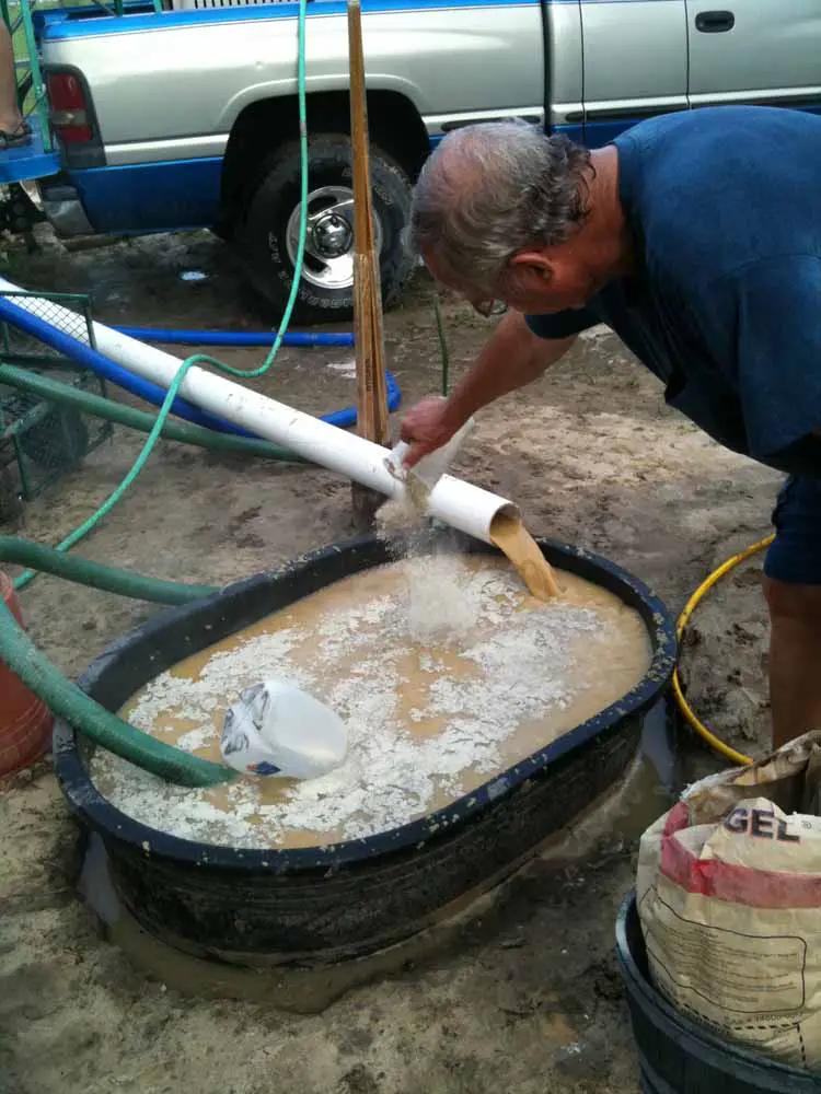
more at http://www.drillyourownwell.com This is an example of a Mud Pump Water Well Drilling Setup utilizing a Portable Mud pit. This particular well was ...

Plan for the best and be ready to take corrective actions when your plans go wrong! This section of the tutorial is designed to help you solve the problems you will encounter when you drill wells. Don"t be discouraged.... use your common sense and learn what you can from the situation you are in! Common problems include:
Large amounts of make-up water is usually required and must be immediately available at all times when drilling in permeable sand and gravel. This is important because drilling fluid sometimes suddenly flows into permeable
If return circulation is suddenly lost, immediately switch the 3-way valve to direct the drilling fluid back to the pit through the by-pass hose (this minimizes the loss of valuable water). Then quickly pull-up the drill pipe 1-2 metres from the bottom of the borehole so that it is less likely to become jammed if the bottom portion of the hole collapses.
(Australian, 1992). A waiting period may allow the fluid to gel in the formation and provide a seal sufficient to allow circulation to be restored. If drilling has been proceeding with water or natural mud, replace the fluid with a thick bentonite slurry, circulate it down the borehole and let it sit for a while. When ready to circulate back
If waiting and thickening the drilling mud do not restore circulation, question why the circulation was lost. If the drilling fluid is being lost into a highly permeable saturation formation, it may be possible to construct an excellent well! Therefore, test the well yield before deciding to proceed with the steps outlined below.
If it is necessary to drill further, try adding thickening materials to the drilling mud. This may occur when extremely unstable formations or those containing open fractures are encountered. Almost any granular flake or fibrous material can be used to provide a wad to block a lost circulation zone. Local materials such as bran, husks, chaff, straw, bark, wood chips, cotton, feathers, or even fibre or wool bedding can usually be located readily and used (Australian, 1992). This material should be pushed down the hole and allowed
The "gunk squeeze" method of sealing off a zone of lost circulation involves forcing a large amount of clay or cement into the zone of water loss (usually at or near the drill bit) and forcing it into the formation where it swells and fills-up any cracks (Australian, 1992). The best way is to mix a very high concentration (6 - 7 kg/L) of bentonite. Once mixed, immediately lower it into the borehole in a sealed bag or container which can be ruptured when opposite the lost circulation zone. This material can be forced into the formation by pressurizing the borehole or by pushing it with a block on the end of the drill string.
If the lost circulation zone cannot be blocked, drilling sometimes may proceed without return circulation. The cuttings are carried away into the formation cavities. It may be necessary to occasionally pump a slug of thick mud to clear the bottom of the hole (Australian, 1992).
Alternatively, casing can be placed to seal-off the problem zone. Ensure that the hole has fully penetrated the problem zone which is to be protected by the casing; Running the casing too soon may not overcome the problems for long. Finally, if none of these options work, it may be necessary to abandon the hole or to continue drilling using a air rotary drilling machine (Australian, 1992).
The main cause of borehole caving is lack of suitable drilling mud (see Section 5). This often occurs in sandy soils where drillers are not using good bentonite or polymer. The problem can be seen when fluid is circulating but cuttings are not being carried-out of the hole. If you continue to push ahead and drill, the bit can become jammed, the hole will collapse when you try to insert the casing or a huge portion of the aquifer may wash-out making it very difficult to complete a good well. The solution is to get some bentonite or polymer or, if necessary, assess the suitability of natural clays for use as drill mud (see Appendix H).
Borehole caving can also occur if the fluid level in the borehole drops significantly (see Footnote #1). Therefore, following a loss of circulation or a night time stoppage, slowly re-fill the borehole by circulating drilling fluid through the drill pipe (pouring fluid directly into the borehole may trigger caving). If caving occurs while drilling, check if cuttings are still exiting the well. If they are, stop drilling and circulate drilling fluid for a while.
Sometimes part of the borehole caves while the casing is being installed, preventing it from being inserted to the full depth of the borehole. When this occurs, the casing must be pulled out and the well re-drilled with heavier drilling fluid. When pulling the casing, no more than 12.19 m (40 ft) should be lifted into the air at any time; more than this will cause thin-walled (Schedule 40) PVC to bend and crack.
The drill pipe and bit may become jammed when the drilling fluid is not allowed to thoroughly clean the borehole prior to stopping to add another joint of drilling pipe or the fluid is too thin to lift gravel from the bottom of the borehole.
Therefore, if the drill bit starts to catch when drilling, stop further drilling and allow the drilling fluid to circulate and remove accumulated cuttings from the borehole. Then continue to drill at a slower rate. If it continues to catch, thicken the drilling fluid.
If the drill bit and pipe become jammed, stop drilling and circulate drilling fluid until it is freed. If circulation is blocked, try to winch the bit and pipe out of the borehole. Stop the engine and use a pipe wrench to reverse rotation (no more than 1 turn or the rod may unscrew!). Rapidly hit the drill pipe with a hammer to try and jolt the bit free.
If these actions are not successful, use lengths of drill pipe without a bit attached or Wattera tubing to "jet out" the cuttings. Attach the pipe or tubing directly to the discharge hose from the mud pump. Thicken the drilling fluid to ensure that the cuttings holding the bit can be removed. Then place tension of the stuck pipe with the drill rig
winch. Once fluid starts to circulate out of the borehole, slowly push the jetting pipe/tubing down the borehole beside the jammed drill pipe until the bit is reached. When fluid starts to circulate out of the stuck pipe and/or it loosens, pull the stuck drill pipe and resume circulation of the thickened drilling fluid back down the drill pipe and bit. Remove the jetting pipe. If water freely circulates out the borehole, slowly lower the drill pipe and bit and resume drilling.
Unfortunately, sometimes wrenches, rocks etc are inadvertently dropped into the borehole when drilling. In addition, the LS-100 is often operated near its design limits with a high degree of structural stress on the drilling stems
If objects are dropped into the borehole after the final depth has been reached, it may be possible to leave them there and still complete the well. If this is not the case, it may be possible to make a "fishing" tool to set-up on the lost gear. For example, if a length of well screen falls down the borehole, it may be possible to send other sections down with a pointed tip on the end and "catch" the lost casing by cramming the pointed end hard into it. These types of "fishing" exercises require innovation and resourcefulness suitable to the circumstances - there is no single right way of doing this work. If sediment has caved in on top of the drill bit or other tools, circulation should be resumed in the hole and the fishing tool placed over the lost equipment.
If the lost tools/bit(s)/drill pipe are not critical, do not even try to retrieve them and just move over and start drilling a new hole. Even if the equipment is important, it is still best to start drilling at a new location while others try to retrieve it since considerable time can be spent on retrieval and there is a low likelihood of success.G-6: Resistant Beds Encountered
Once a resistant bed is encountered and the rate at which the drill bit is penetrating the formation drops dramatically, a decision needs to be made whether to stop drilling or to continue. If the resistant bed is comprised of gravels, the drilling fluid may need to be thickened to lift-out the cuttings. If the resistant bed is hard granite, drilling with the LS-100 should cease. Other drilling methods should be found or drilling should be attempted at another location. Remember, to help as many people as possible and to get the best value for donor dollars, DRILL THE EASY BOREHOLES FIRST!! It is not worth wearing-out the equipment by grinding away for hours and hours to gain a foot or two of borehole depth.
It is sometimes necessary to drill through aquifers which contain contaminated water. In these situations, drill until a confining layer (clay or rock) is encountered. Insert the casing and then seal the annular space with a grout slurry. To avoid damaging the grout seal, let the grout cure for at least 12-24 hours prior to resuming drilling
Sometimes the water in a confined aquifer is under so much pressure that it will flow out the top of a well which is drilled into it. Special precautions and construction techniques must be used to control the water pressure and flow or serious environmental problems can result. The free flow of excess water to waste can result in the depletion of a valuable resource and in unnecessary interference with other well supplies. Free flow from the well casing or a breakout of uncontrolled flow around the well casing can cause serious erosional and flooding problems on the owner"s and adjacent properties that may be very difficult and costly to correct.
Sometimes natural flow can be brought under control by extending the well casing 1.5 - 6 m (5 - 20 ft) into the air. This can allow the pressure in the pipe to balance that within the aquifer. A spout with a tap can then be installed in the side of the casing. A hand pump can be installed at a later date if the pressure in the pipe drops over time.
Sometimes a very thin or relatively impermeable aquifer is encountered which must be developed to provide a reliable water supply. Ensure that the borehole penetrates the full thickness of the aquifer, extending as far below it as possible. Install the well screen adjacent to the entire aquifer thickness with solid casing installed above and below it. After developing the well, install the pump cylinder as low as possible in the well.
If a well is being completed in a fine sand/silt aquifer within 15-22 m (50 - 75 ft) of ground surface, a 20 cm (8 in) reamer bit has sometimes been used (e.g. Bolivia). This makes it possible to install a better filter pack and reduces entrance velocities and passage of fine silt, clay and sand particles into the well.
Yield can be maximized by adding a small amount of a polyphosphate to the well after it has been developed using conventional techniques. The polyphosphate helps remove clays that occur naturally in the aquifer and that were introduced in the drilling fluid (see Footnote #3).
Enough time must be allowed between introduction of the polyphosphate and development, usually overnight, so the clay masses become completely desegregated (Driscoll, 1986). After the polyphosphate solution is surged into the screen (see Footnote #4), water should be added to the well to drive the solution farther into the formation.
Sometimes it is not possible to lower the casing and well screen to the bottom of the hole. This can be due to part of the borehole collapsing, clays in the aquifer swelling and reducing the size of the borehole or the borehole being crooked resulting in the casing digging into the wall of the borehole. These problems are most common where 10 cm (4 in) schedule 40 casing is being inserted into a 15 cm (6 in) borehole. This is because the outside diameter of the casing couplers is 13 cm (5.25 in), leaving an annular space of just over a quarter inch on each side of the casing! It does not take much swelling of clays or slight deviation from vertical to result in the casing jamming.
To avoid these problems, minimize the amount of pull-down pressure when drilling so that the bit can run freely under its own weight. Also, casing there is no problem with casing jambing when 7.6 cm (3 in) schedule 40 casing is used. Keep in mind, however, that a 7.6 cm (3 in) casing is too small to take a 6.4 cm (2.5 in) pump cylinder or most submersible pumps. Usually, however, these issues are not a concern.
If you need to construct a 10 cm (4 in) well and the casing has jammed, the best solution is to pull the casing / screen from the borehole. This involves cutting the casing into 6-12 m (20 - 40 ft) lengths (longer than this will result in the casing bending and cracking). Slowly re-drill the borehole with a 15 cm (6 in) reamer bit or, if available, a 18 or 20 cm (7 or 8 in) bit. Concentrate on the portion of the borehole where the casing jammed. While this can take several hours, it often eliminates blockages and allows the casing to slide to the bottom of the borehole. As soon as the reaming is completed, re-glue and re-insert the casing.
If it still jams, your last resort is to try and "wash" the casing down by installing the drilling rods down inside the casing and circulating drilling fluid through a wash-down valve (see Section 7). Fluid is pumped down through the casing and out the bottom of the screen where it will pick-up and carry soil particles back up to the surface between the casing and the hole walls. The amount of water passing through the screen openings can be minimized by attaching a surge block to the lower end of the drill string. Be sure to secure the pipe with a rope to prevent the casing from dropping if the blockage was localized and is removed with the circulation process. Failure to do so could result in the casing dropping to the bottom of the hole without the casing extending to the surface. When the casing is finally installed to the appropriate depth, stabilize the open bottom
end of the casing by pouring in 30-60 cm of coarse gravel into the well. If the casing still jams above the water bearing formation, the only other option is to obtain and install 7.6 cm (3 in) casing and well screen.
A well can suddenly no longer provide the same amount of water that it did before. If you move the pump handle and it feels OK but little or no water comes out the spout, the well may be dry. Confirm this by measuring the water level in the well and try to determine which of the following causes is responsible:
Natural Lowering of the Water Table: Water levels in shallow dug and bored wells experience large fluctuations due to climatic conditions. The natural seasonal change in water level often will often be several metres. This is likely the cause of the drop in yield if the level of water within the well does not rise up, even several hours after pumping. All that can be done is to construct a new well, ensuring that the well casing is set far enough below the water table (ideally 5 to 10 metres) to assure an adequate water supply during the dry summer periods when the water level declines. Also, check how many people are drawing water from the
Well Water Interference: The construction of water and sewer mains, drainage ditches and highways (road cuts) can occasionally affect ground-water levels and interfere with nearby shallow wells. In addition, the static water level in a well may be affected by large withdrawals of ground water from nearby large capacity wells or de-watering equipment for construction works (see Footnote #5). The potential for well interference depends greatly on the lithology of the producing formation and the magnitude of well usage.
Screen Blockage: Sometimes the problem is that the well screen has plugged-up with fine sand and silt particles, with accumulated iron deposits or with growths of nuisance bacteria (naturally occurring, non-health related bacteria with can produce rotten egg smells, random slugs of iron rich water etc). This is likely the case if the water level in the well is near its original construction level but drops to the bottom of the pump cylinder as soon as the well is pumped. The well should be extensively re-developed to try and restore the efficiency of the screen and gravel pack (see
1 The drilling fluid prevents caving of the borehole because it exerts pressure against the wall. As long as the hydrostatic pressure of the fluid exceeds the earth pressures and any confining pressure in the aquifer, the hole will remain open. The pressure at any depth is equal to the weight of the drilling fluid column above that point.
2 Before drilling out the grout plug, the effectiveness of the seal can be checked by measuring water-level change in the casing over time. In wells with a low static water level, the casing can be filled with water or drilling fluid and later checked for any water loss. If the static water level is high, the casing can be nearly emptied and any influx of water into the casing can be measured.
L (100 gal) of water in the screen. 0.9 kg (2 lbs) of sodium hypochlorite should also be added to every 100 gal of water in the well to control bacterial growth promoted by the presence of polyphosphates (Driscoll, 1986). Polyphosphates should be premixed before introduction into the well because they do not mix easily with cold water. Occasionally the mix water is heated to help dissolve the chemical (Driscoll, 1986). Polyphosphates should NOT be used in formations with thinly bedded clays and sands because these chemicals tend to make the clays near the borehole unstable, causing them to mix with the sand (Driscoll, 1986) continually passes into the borehole during pumping (Anderson, 1993).
5 When a well is pumped, the water level in the immediate area of the well is lowered and a cone of depression develops around the well. The size and the shape of the cone will depend on the aquifer characteristics of the water-bearing formation in which the well is completed and the rate of pumping. This is likely the cause if there are two or more wells located within 100 m of each other and if water levels return to normal in both wells once pumping has stopped or within some reasonable time afterwards. Water level recovery depends on the quantity of water withdrawn from the aquifer and the length of time the wells were pumped. All that can be done is
Australian Drilling Industry Training Committee Ltd (1992) Australian Drilling Manual 3rd edition", Macquarie Centre: Australian Drilling Industry Training Committee Ltd, ISBN 0-949279-20X.

I’ve run into several instances of insufficient suction stabilization on rigs where a “standpipe” is installed off the suction manifold. The thought behind this design was to create a gas-over-fluid column for the reciprocating pump and eliminate cavitation.
When the standpipe is installed on the suction manifold’s deadhead side, there’s little opportunity to get fluid into all the cylinders to prevent cavitation. Also, the reciprocating pump and charge pump are not isolated.
The gas over fluid internal systems has limitations too. The standpipe loses compression due to gas being consumed by the drilling fluid. In the absence of gas, the standpipe becomes virtually defunct because gravity (14.7 psi) is the only force driving the cylinders’ fluid. Also, gas is rarely replenished or charged in the standpipe.
The suction stabilizer’s compressible feature is designed to absorb the negative energies and promote smooth fluid flow. As a result, pump isolation is achieved between the charge pump and the reciprocating pump.
The isolation eliminates pump chatter, and because the reciprocating pump’s negative energies never reach the charge pump, the pump’s expendable life is extended.
Investing in suction stabilizers will ensure your pumps operate consistently and efficiently. They can also prevent most challenges related to pressure surges or pulsations in the most difficult piping environments.
Sigma Drilling Technologies’ Charge Free Suction Stabilizer is recommended for installation. If rigs have gas-charged cartridges installed in the suction stabilizers on the rig, another suggested upgrade is the Charge Free Conversion Kits.

5-1. Mud Rotary Drilling. Rotary drilling with mud is the most widely used method for water-well construction. A rotary drill rig has three functions: rotating the drill string, hoisting the drill string, and circulating the drilling fluid. A bit is rotated against the formation while mud is pumped down the drill pipe, through ports in the bit, and back to the ground surface through the annulus between the drill pipe and the borehole wall. (Table 5-1 shows the relative performance of drilling methods in various geologic formations.) Drill cuttings rise to the ground surface in the drilling fluid. Rotary drilling is sometimes called mud rotary drilling. Drill pipes or rods are joined to a bit to form the drill string. The drill pipe is the link transmitting torque from the rig to the bit, and the pipe carries the drilling fluid down the hole.
a. Rotary Rigs. Rotary rigs vary in design. Drilling rigs are truck- or trailer-mounted and are powered by an on-board engine or by a PTO from the truck transmission. Power is delivered to the various components through hydraulic pumps and motors or through mechanical transmissions and clutches and geared on roller-chain drives. Many drill rigs may use both mechanical and hydraulic drives. Torque is applied to the drill string, which rotates by using three basic designs--rotary table, top head, and quill-and-drive bar. Military drilling machines use rotary table drives.(1) Rotary Table. The rotary table is a rotating platform that transmits torque to the drill rod through the kelly. The kelly, which is attached to the mud swivel, is the uppermost section of the drill string that passes through the rotary table. The drill string may be square, hexagonal, or round with grooves or flukes on the outside wall. The drive kelly bar slides through the rotary table while rotating. By removing the kelly bar, you can add drill pipe and work the pipe through the open hole in the rotary table. The rotary table normally is a mechanical, positive drive mechanism.
(4) Mud Pump. A mud pump (Figure 5-1) on a rotary drill is usually a positive-displacement, double-acting piston pump with capacities ranging from one to several hundred GPM at pressures up to several hundred psi. Power may be provided through a mechanical PTO and clutch, with or without a separate transmission. Power may also be provided by a separate engine or a hydraulic or air motor. Other types of pumps are often used successfully, but their limited pressure capacity may jeopardize the success of the drilling operation. Most well-drilling machines have dual piston, double-acting, positive-displacement mud pumps. Pump capacity (volume and pressure) can limit the effective depth of a drilling operation. The horsepower required to drive a mud pump often exceeds the power required to hoist and rotate the drill string.
c. Rotary Operation. Standard rotary drilling involves the bit rotating against the formation. Drilling fluid is pumped through the drill string and face of the drill bit and backup the annulus to the surface. The rotary action of the bit loosens the material, while the drilling fluid cools and lubricates the drill pipe and bit and carries cuttings to the surface. The drilling fluid is under high hydrostatic pressure and supports the wall of the borehole against caving. The properties of the drilling fluid are important to the drilling operation. Well drillers must have knowledge of drilling fluids and their use for successful rotary drilling. Drillers must also know about drilling-fluid additives used to prevent problems in drilling. Preventing drilling problems, such as an unstable borehole wall or a stuck tool, is easier than fixing the problem after it occurs. See paragraph 5-1e for information on drilling fluids.
Before drilling with mud, build a mud pit. The pit may be either a portable pit or an excavated mud pit. The decision depends on the hole depth and the alternatives available. See paragraph 5-1e(9) for more information on mud pits.
d. Variables. Bit design, weight on bit, rotation speed, fluid consistency, and cumulation pressure and velocity affect rotary drilling. Experience helps the driller handle unique problems and conditions. Continue to experiment wherever you drill to develop the best drilling procedure. Before starting the hole, plumb the kelly to provide a straight hole (Figure 5-3).
(2) Weight on Bit. Adding weight on the bit increases the torque required for rotation. Too much weight can cause excessive penetration and produce cuttings that are too large and heavy. Large cuttings are difficult to wash out and may cause gumming and premature failure of the bit. Insufficient weight reduces or stops penetration and can produce fine cuttings. In cohesive soils, fine cuttings may thicken the drilling fluid and fail to settle in the mud pit. How weight is applied can also cause serious alignment problems and difficulty in well construction. Rotary-drilled boreholes spiral slightly and are seldom straight. Once spindling occurs, weight added by pulling down with the drill rig bends the string and magnifies the deviation. You should never use the chain pulldown to advance the hole beyond the first run (20 feet). Ideally, keep the drill string in tension. Add drill collars (heavy wall drill steel) at the bottom just above the bit. See Table 5-3 for drill collar weights.
Bit weight required to cut rock depends on the design of the bit and the strength of the rock. Roller bits need a minimum of 2,000 psi of bit diameter for soft rock and shale and a maximum of 6,000 psi of bit diameter for hard rock. Before drilling, add drill collars instead of drill pipe until the load is sufficient for reasonable cutting. As you dig deeper and add drill pipe, you may have to hold back on the drill string. See Table 5-4 for weight on bit and rotary speed.
(5) Fluid Requirements. Fluid requirements depend on size, weight, nature of cuttings, and circulation velocity. Velocity depends on capacity and condition of the mud pump, annular area in the borehole, and the stability and permeability of the formation. See paragraph 5-1e for more information on drilling fluids.
(6) Circulation Pressure and Velocity. These elements of the drilling fluid are controlled by the pump capacity and speed. The fluid"s density, velocity, and viscosity let it carry cuttings. If the drilling fluid is too thick, cuttings will not settle in the mud pit. Sufficient velocity with a fluid of low viscosity (even water) will carry drill cuttings to the surface. Excessive velocity will erode the wall of the hole to the extent of failure.
Pump pressure results from flow resistance caused by viscosity, friction, weight of the fluid column, or restrictions in the circulating system. Pressure should be exerted at the ports in the bit, causing a downward jetting as the fluid exits. Regulate mud-pump pressure by varying the RPM of the pump. Mud-pump pressure against the bit is not harmful if it does not exceed the operating pressure of the pump. Other sources of fluid pressure can be detrimental. Pressure from friction occurs if the drill string is long for its inside diameter or pipes are internally upset. Frictional pressure increases wear in the pump. Pressure from the weight of the fluid column in the annulus or from a restriction in the annulus caused by an accumulation of cuttings indicates insufficient cleaning. This type of pressure can cause formation damage, resulting in lost circulation and wall damage.
e. Drilling Fluids. Drilling fluid is circulated in rotary drilling to cool, clean, and lubricate the drill string, to flush cuttings from the hole, and to stabilize the borehole wall. Water is the basic fluid and is satisfactory for lubricating and cooling the tools. However, water has limited abilities to carry cuttings and stabilize the borehole wall. Many drilling fluid additives are prepared and formulated for various purposes. Polymer fluids and water-based clay fluids (muds) are the primary additives used in water-well drilling. Table 5-5 lists drilling fluids.
Mud cools and lubricates through heat absorption from the bit and reduction of drill-string abrasion against the borehole wall. Heat is generated as the bit scrapes and grinds. Without the cooling fluid, the bit would overheat and be useless. Research indicates that removing the cuttings around and under the bit is the most important factor in keeping the bit cool. Requirements for cooling fluid are less than those for removing the cuttings.
Therefore, if you keep the borehole clean with the fluid as you drill, you also cool and lubricate. This is true with clay muds and polymer fluids. Clay muds are colloidal suspensions. Solutions are chemical mixtures that cannot be separated by simple filtering. Suspensions are physical mixtures of solids and liquid that can be separated by filtering. This distinction underlies the difference in behavior between drilling polymers (solutions) and drilling muds (suspensions). You can mix natural clays with water for use as a drilling mud. Drillers often use water in shallow clayey strata and depend on the formation clay to produce a suitable mud. Natural-clay mud properties are marginal for good water-well drilling.
Hydrostatic pressure allows the fluid to support the borehole wall and is a function of the density or weight of the mud column. Important characteristics of a drilling mud are viscosity and weight to carry cuttings, gel strength, yield point, and active clay solids for filter cake. Use the following formula to calculate hydrostatic pressure:
(1) Polymers. Polymer fluids are water-based and very low in solids. The polymer admixture can be organic, inorganic, natural, synthetic or synthetically formulated natural polymers. Polymer additives are formulated for various drilling-fluid purposes and can be used alone or to enhance clay muds. Polymers, containing salt and other contaminants, are available and are compatible with water. Polymers are more sensitive to pH than are bentonite muds. Change the pH to effect desirable changes in the polymer fluid. Drilling-fluid weight impacts drilling rate and high-density drilling fluid reduces drilling rote. There is strong indication that the solids of a fluid have a similar effect as density. Polymer fluids are very different from clay muds because a large part of the polymer is soluble in water and becomes a solution when mixed with water. Long, complicated molecular chains tie up the water and can build viscosity without solids. In water-well drilling, many polymers are manufactured for producing drilling fluids, such as E-Z Mud, Revert, and Poly-Sal. E-Z Mud is a synthetic, inorganic polymer. Revert is a natural, organic polymer fluid derived from the guar plant.
Polymers are generally best mixed through a mud gun. Polymers used for special purposes are available from the manufacture complete with specifics on how to use the product. Most polymers can hydrate more water than a high-grade bentonite. Up to ten times more bentonite is needed to build the same viscosity in a given amount of fluid, depending on the quality of the polymer. A polymer does not fully hydrate as quickly as bentonite. Mix the polymer very slowly through the mud gun a minimum of four hours before using for more complete hydration. The fluid will thicken as hydration continues, so do not mix to the desired viscosity. Some polymers possess physical qualities that can result in unusual hydration, gelling and viscosity. Follow the manufacturer"s recommendations for hydration. Factors that affect the viscosity are quality of polymer, concentration and size of colloid, metallic ions in mixing water, temperature, rate of shear, and pH.
Water is the primary building block for drilling fluids. Water quality affects the overall performance of drilling fluids. The action of bentonite in water is seriously impaired by dissolved acids or salty substances. Acidic water usually contains dissolved metals that cannot be used unless treated. Hard water affects the suspending and sealing qualities of bentonite. You can test the pH level by using paper pH strips. The pH level should be 8 to 9. If the water is too acidic, treat it with soda ash at a ratio of 1 to 5 pounds of soda ash per 100 gallons of water. Following treatment, retest the pH level as before.
Do not use water from wetlands, swamps, or small ponds for mixing drilling fluids because the water may be contaminated. If you use water from these sources, chlorinate the water before making the drilling fluid. Be careful because chlorine removes metallic ions that are necessary for viscosity in polymers. Adjust the pH of drilling water to 7.5.
Polymer drilling fluids can break down viscosity. Without treatment, the viscosity of some polymers (Revert) completely breaks down in one to six days depending mainly on temperature. You can correct this by adding chlorine. Revert requires Fast Break; E-Z Mud needs sodium hypochlorite at a ratio of 2 quarts for every 100 gallons of water. Other polymers, such as E-Z Mud and Poly-Sal, maintain their viscosity for long periods of time since natural breakdown is not significant. Table 5-6 lists additives for drilling fluids.
Some drilled fines (clay, silt) circulate back down the hole. Recirculated solids are much less a problem with polymer fluids than with clay fluids. Revert will not hydrate in water containing any appreciable amount of borate. However, Borax can be used to produce a gel plug in hydrated guar-gum polymer. With a pH of 7.5, the borate cross-links the polymeric chains and forms a strong three-dimensional molecular gel. If a strong gel plug is necessary to get through a lost circulation zone, mix 1 cup of borax in 5 gallons of water and pour slowly into the pump section while pumping at idle speed. When the berated fluid (stringy gelled mass) recirculates, stop pumping for one-half hour. Resuming normal drilling should be possible after wasting the borated fluid. Repeat the procedure, if necessary. Although the polymer fluid is not thixotropic and has no gel strength, it thins somewhat while being pumped.
Polymer fluids build a type of membrane on the wall different from clay mud. Unnatural clay particles (bentonite) are not introduced into the hole. Since the polymer fluid is partly a thick solution, infiltration into the permeable wall is reduced. However, insoluble portions of some polymer colloids do exist. The insoluble and cuttings are surrounded with thick coatings that are more impermeable per unit thickness than a bentonite filter cake. The insoluble and cuttings seal the wall of the hole with a thinner, less active layer. The impermeable layer performs the same function as the filter cake in clay muds but does not restrict the annulus.
The colloids in the polymer fluid are nonionic, have no chemical interaction, and are easier to remove in water-well development. When the viscosity of the fluid is broken, much of the cohesive function of the thin film becomes a water-like liquid and is washed out of the water well. Field testing of polymer fluids, using the falter press and the Marsh funnel, yields different results. The mud balance for measuring fluid density does not change. Weighing of the polymer fluid is limited. You can add sodium chloride to the fluid to bring the weight up to about 10 pounds per gallon. The addition of heavy solids (ground barite) is ineffective because of the polymer fluid"s lack of thixotropic qualities.
(2) Mud Products. Commercially processed clays for drilling are bentonite and attapulgite. Bentonite is superior except in brackish or salty water. (Use attapulgite in these waters.) Bentonite forms naturally from decomposition of volcanic ash when ground. Bentonite consists of aggregates of flat platelets in face-to-face contact. Bentonite is mined in many states, but the best grade (Wyoming bentonite) is mined only in Wyoming and South Dakota. Wyoming bentonite contains sodium montmorillonite (the active part of the clay mineral) and is small in size, which is important in building viscosity.
Mud drilling fluids should be mixed with a mud gun. When agitated and sheared with water, the bentonite platelets absorb more than 25 times their own weight in water, separate, and swell. The amount of surface area wetted determines the ability of the particle to build viscosity. One ounce of Wyoming bentonite dispersed in water has more surface area than five football fields. Interparticle activity between platelets gives the mud its gel properties. The chemical composition of the mixing water affects the ability of bentonite to develop desirable qualities. These qualities can be manipulated by adding small amounts of various chemicals.
(3) Mud Viscosity. True viscosity is a term relating only to true (Newtonian) fluids, such as water, and is a proportional constant between shear stress and shear rate in laminar flow. Drilling muds act differently in that the proportion between shear stress and shear rate is reduced when shear rate is increased. Drilling muds are thixotropic. The viscosity of a drilling mud refers to the thickness of the mud while flowing. Gel strength is the term used to describe the thickness of drilling mud at rest. Gel strength develops over a short period of time.
Yield point is the mud quality broadly included in viscosity. You need more stress (pump pressure) to cause the gelled drilling mud to start flowing than to sustain flow once the gel is broken. The stress required to initiate shear or flow is the gel strength of the mud. The stress required to maintain shear is the viscosity. You want a higher yield strength with respect to the gel strength so the mud becomes very thin in flow shear.
The primary function of viscosity is to help lift drill cuttings from the borehole. Other mud characteristics affecting lifting capacity are density, velocity, and flow patterns. Gel strength holds the cuttings in suspension at the bottom of the hole when circulation is stopped. The stress (hydraulic pressure) required to break the gel strength to initiate cumulation can be detrimental. Required bottom-hole pressures can cause fracturing or opening of fractures in the formation, resulting in loss of drilling fluid, formation damage, and borehole wall damage. Down-hole pressure required to continue circulation depends on friction, density (or weight of fluid column), and viscosity of the mobilized fluid. These pressures can also cause serious problems. Therefore, it is desirable to use a drilling mud of relatively low density and viscosity, moderate gel strength, and high yield point relative to the gel strength (a very thin fluid in circulation).
(4) Mud Testing. The Marsh funnel (Figure 5-6) is routinely used to give an indication of thickness or apparent viscosity of drilling fluid. The Marsh funnel is 12 inches long and 6 inches in diameter and has a No. 12 mesh strainer and a 1,000-milliliter (ml) cone. The funnel has a 2-inch-long, calibrated, hard-rubber orifice with an inside diameter of 3/16 inch. The funnel"s cup is marked with a capacity of 1,000 ml. Use the following procedure for the Baroid Marsh funnel:Hold or mount the funnel in an upright position, and place a finger over the hole.
The funnel viscosity measurement obtained is influenced considerably by the gelation rate of the mud sample and its density. Because of these variations, the viscosity values obtained with the Marsh funnel cannot be correlated directly with other types of viscometers and/or rheometers. Graduated in cubic centimeters (cc) and fluid ounces, the 1,000-cc measuring cup is designed specifically for use with the Baroid Marsh funnel viscometer. A quart volume is clearly marked on the measuring cup.
You can use test readings as an indicator of changes in mud that might lead to problems. Therefore, conduct Marsh-funnel tests before beginning operations and record the findings. Take mud samples for each test from the same location in the circulating system just before returning to the hole. The apparent viscosity of the drilling mud in motion affect


 8613371530291