
drill well mud pump free sample

OK, all y’all air drillers just thumb on over to Porky’s column or something. This is for mud drillers. On second thought, I know a lot of you air guys drill about three mud wells a year, and consider it a hassle to rig up mud. So, maybe something I say will be interesting …
The mud pump is the heart of the circulating system, and mud is the blood circulating in the hole. I’ve talked about mud before and will again, but this month, let’s talk about the pump.
Historically, more wells, of every kind, have been drilled with duplex pumps than any other kind. They are simple and strong, and were designed in the days when things were meant to last. Most water well drillers use them. The drawbacks are size and weight. A pump big enough to do the job might be too big to fit on the rig, so some guys use skid-mounted pumps. They also take a fair amount of horsepower. If you were to break down the horsepower requirements of your rig, you would find out that the pump takes more power than the rotary and hoist combined. This is not a bad thing, since it does a lot of the work drilling. While duplex pumps generally make plenty of volume, one of the limiting factors is pressure. Handling the high pressures demanded by today’s oil well drilling required a pump so big and heavy as to be impractical. Some pretty smart guys came up with the triplex pump. It will pump the same — or more — volume in a smaller package, is easy to work on and will make insane pressure when needed. Some of the modern frack outfits run pumps that will pump all day long at 15,000 psi. Scary. Talk about burning some diesel.
The places that triplex pumps have in the shallow drilling market are in coring and air drilling. The volume needs are not as great. For instance, in hard rock coring, surface returns are not always even seen, and the fluid just keeps the diamonds cool. In air drilling, a small triplex is used to inject foam or other chemicals into the air line. It’s basically a glorified car wash pump. The generic name is Bean pump, but I think this just justifies a higher price. Kinda like getting the same burger at McDonald’s versus in a casino.
One of the reasons water well drillers don’t run triplex pumps, besides not needing insane pressure, is they require a positive suction head. In other words, they will not pick up out of the pit like a duplex. They require a centrifugal charging pump to feed them, and that is just another piece of equipment to haul and maintain.
This brings me to another thought: charging. I know a lot of drillers running duplex pumps that want to improve the efficiency of their pumps. Duplexes with a negative suction head generally run at about 85 percent efficiency. The easy way to improve the efficiency is to charge them, thus assuring a 100 percent efficiency. This works great, but almost every one of them, after doing all that work and rigging up a charging pump, tells me that their pump output doubled. Being the quiet, mild mannered type that I am, I don’t say “Bull,” but it is. A duplex pump is a positive displacement pump. That means that it can deliver no more than the displacement it was designed for. You can only fill the cylinder up until it is full. It won’t take any more. The one exception to this is when you are pumping at very low pressure. Then the charging pump will over run the duplex, float the valves and produce a lot more fluid. Might as well shut off the duplex and drill with the charging pump.
Another common pump used in the water well industry is the centrifugal. You see them mostly on air rigs that don’t use mud too often. They have their place, but are a different breed of cat. They are not positive displacement. Flow is a function of speed and horsepower up to the limits of the pump. After that, they just dead-head. With large diameter drill pipe they make a lot of mud, but after the hole gets deeper, friction losses — both inside and outside the drill pipe — build up. This means that the deeper you go, the less circulation you have. This slows the whole process. Positive displacement pumps don’t do this; they pump the same per stroke regardless of pressure. It just takes more horsepower. Also, displacement calculations like bottoms-up time and cement placement are just about impossible. One way to get around the limited pressure of centrifugal pumps is to run two of them in series. I’ve seen a few of these rig-ups and they work very well for large diameter drilling. They will make almost the same pressure as a big duplex for a lot less money. They are still variable displacement, but they roll so much fluid that it doesn’t seem to matter. And run at pretty reasonable depths, too: 300 to 400 psi at 400 gpm is not uncommon with two 3 x 4 centrifugal pumps in series.
I reckon there are pumps for every type of drilling. It is just a matter of using the right one correctly. I once drilled a 42-inch hole 842 feet deep with a 5½ x 8 duplex. Talk about long bottoms-up time … but we got the casing in with less than two feet of fill on bottom! Took time, but we got-er-done.

When choosing a size and type of mud pump for your drilling project, there are several factors to consider. These would include not only cost and size of pump that best fits your drilling rig, but also the diameter, depth and hole conditions you are drilling through. I know that this sounds like a lot to consider, but if you are set up the right way before the job starts, you will thank me later.
Recommended practice is to maintain a minimum of 100 to 150 feet per minute of uphole velocity for drill cuttings. Larger diameter wells for irrigation, agriculture or municipalities may violate this rule, because it may not be economically feasible to pump this much mud for the job. Uphole velocity is determined by the flow rate of the mud system, diameter of the borehole and the diameter of the drill pipe. There are many tools, including handbooks, rule of thumb, slide rule calculators and now apps on your handheld device, to calculate velocity. It is always good to remember the time it takes to get the cuttings off the bottom of the well. If you are drilling at 200 feet, then a 100-foot-per-minute velocity means that it would take two minutes to get the cuttings out of the hole. This is always a good reminder of what you are drilling through and how long ago it was that you drilled it. Ground conditions and rock formations are ever changing as you go deeper. Wouldn’t it be nice if they all remained the same?
Centrifugal-style mud pumps are very popular in our industry due to their size and weight, as well as flow rate capacity for an affordable price. There are many models and brands out there, and most of them are very good value. How does a centrifugal mud pump work? The rotation of the impeller accelerates the fluid into the volute or diffuser chamber. The added energy from the acceleration increases the velocity and pressure of the fluid. These pumps are known to be very inefficient. This means that it takes more energy to increase the flow and pressure of the fluid when compared to a piston-style pump. However, you have a significant advantage in flow rates from a centrifugal pump versus a piston pump. If you are drilling deeper wells with heavier cuttings, you will be forced at some point to use a piston-style mud pump. They have much higher efficiencies in transferring the input energy into flow and pressure, therefore resulting in much higher pressure capabilities.
Piston-style mud pumps utilize a piston or plunger that travels back and forth in a chamber known as a cylinder. These pumps are also called “positive displacement” pumps because they literally push the fluid forward. This fluid builds up pressure and forces a spring-loaded valve to open and allow the fluid to escape into the discharge piping of the pump and then down the borehole. Since the expansion process is much smaller (almost insignificant) compared to a centrifugal pump, there is much lower energy loss. Plunger-style pumps can develop upwards of 15,000 psi for well treatments and hydraulic fracturing. Centrifugal pumps, in comparison, usually operate below 300 psi. If you are comparing most drilling pumps, centrifugal pumps operate from 60 to 125 psi and piston pumps operate around 150 to 300 psi. There are many exceptions and special applications for drilling, but these numbers should cover 80 percent of all equipment operating out there.
The restriction of putting a piston-style mud pump onto drilling rigs has always been the physical size and weight to provide adequate flow and pressure to your drilling fluid. Because of this, the industry needed a new solution to this age-old issue.
As the senior design engineer for Ingersoll-Rand’s Deephole Drilling Business Unit, I had the distinct pleasure of working with him and incorporating his Centerline Mud Pump into our drilling rig platforms.
In the late ’90s — and perhaps even earlier — Ingersoll-Rand had tried several times to develop a hydraulic-driven mud pump that would last an acceptable life- and duty-cycle for a well drilling contractor. With all of our resources and design wisdom, we were unable to solve this problem. Not only did Miller provide a solution, thus saving the size and weight of a typical gear-driven mud pump, he also provided a new offering — a mono-cylinder mud pump. This double-acting piston pump provided as much mud flow and pressure as a standard 5 X 6 duplex pump with incredible size and weight savings.
The true innovation was providing the well driller a solution for their mud pump requirements that was the right size and weight to integrate into both existing and new drilling rigs. Regardless of drill rig manufacturer and hydraulic system design, Centerline has provided a mud pump integration on hundreds of customer’s drilling rigs. Both mono-cylinder and duplex-cylinder pumps can fit nicely on the deck, across the frame or even be configured for under-deck mounting. This would not be possible with conventional mud pump designs.
The second generation design for the Centerline Mud Pump is expected later this year, and I believe it will be a true game changer for this industry. It also will open up the application to many other industries that require a heavier-duty cycle for a piston pump application.

There are many different ways to drill a domestic water well. One is what we call the “mud rotary” method. Whether or not this is the desired and/or best method for drilling your well is something more fully explained in this brief summary.
One advantage of drilling with compressed air is that it can tell you when you have encountered groundwater and gives you an indication how much water the borehole is producing. When drilling with water using the mud rotary method, the driller must rely on his interpretation of the borehole cuttings and any changes he can observe in the recirculating fluid. Mud rotary drillers can also use borehole geophysical tools to interpret which zones might be productive enough for your water well.
The mud rotary well drilling method is considered a closed-loop system. That is, the mud is cleaned of its cuttings and then is recirculated back down the borehole. Referring to this drilling method as “mud” is a misnomer, but it is one that has stuck with the industry for many years and most people understand what the term actually means.
The water is carefully mixed with a product that should not be called mud because it is a highly refined and formulated clay product—bentonite. It is added, mixed, and carefully monitored throughout the well drilling process.
The purpose of using a bentonite additive to the water is to form a thin film on the walls of the borehole to seal it and prevent water losses while drilling. This film also helps support the borehole wall from sluffing or caving in because of the hydraulic pressure of the bentonite mixture pressing against it. The objective of the fluid mixture is to carry cuttings from the bottom of the borehole up to the surface, where they drop out or are filtered out of the fluid, so it can be pumped back down the borehole again.
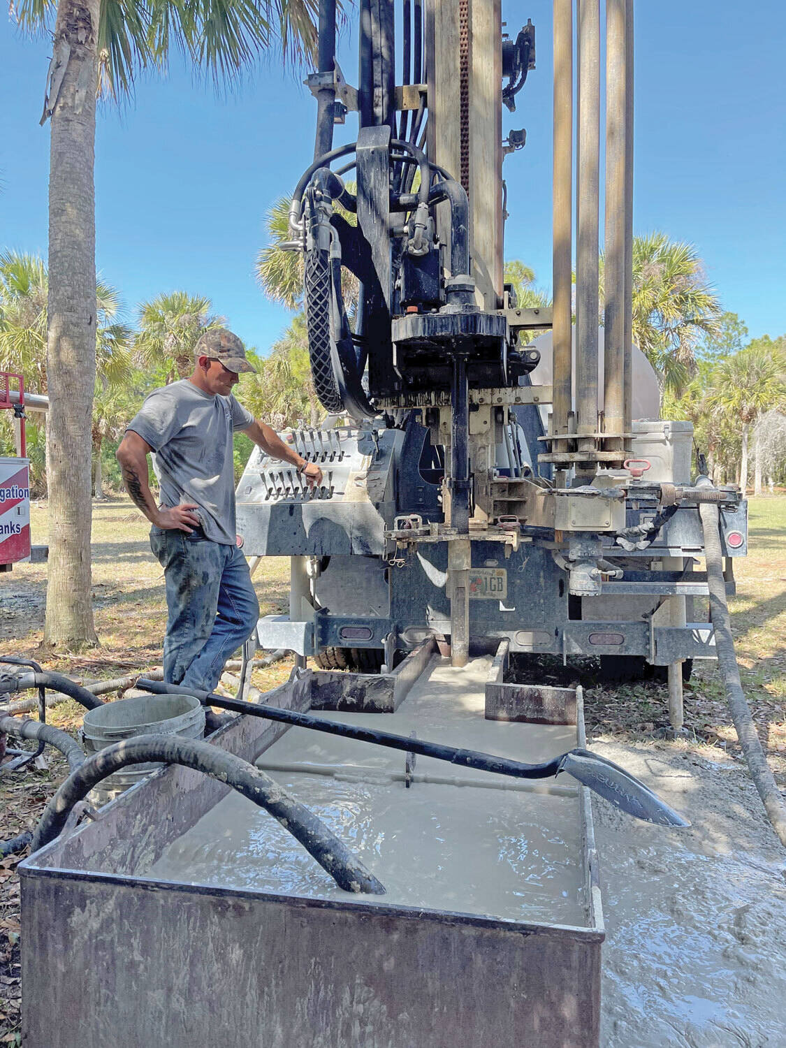
When using the mud rotary method, the driller must have a sump, a tank, or a small pond to hold a few thousand gallons of recirculating fluid. If they can’t dig sumps or small ponds, they must have a mud processing piece of equipment that mechanically screens and removes the sands and gravels from the mixture. This device is called a “shale shaker.”
The driller does not want to pump fine sand through the pump and back down the borehole. To avoid that, the shale shaker uses vibrating screens of various sizes and desanding cones to drop the sand out of the fluid as it flows through the shaker—so that the fluid can be used again.
When the borehole has reached the desired depth and there is evidence that the formation it has penetrated will yield enough water, then it’s time to make the borehole into a well.
Before the well casing and screens are lowered into the borehole, the recirculating fluid is slowly thinned out by adding fresh water as the fluid no longer needs to support sand and gravel. The driller will typically circulate the drilling from the bottom up the borehole while adding clear water to thin down the viscosity or thickness of the fluid. Once the fluid is sufficiently thinned, the casing and screens are installed and the annular space is gravel packed.
Gravel pack installed between the borehole walls and the outside of the well casing acts like a filter to keep sand out and maintain the borehole walls over time. During gravel packing of the well, the thin layer of bentonite clay that kept the borehole wall from leaking drilling fluid water out of the recirculating system now keeps the formation water from entering the well.
This is where well development is performed to remove the thin bentonite layer or “wall cake” that was left behind. Various methods are used to remove the wall cake and develop the well to its maximum productivity.
Some drillers use compressed air to blow off the well, starting at the first screened interval and slowly working their way to the bottom—blowing off all the water standing above the drill pipe and allowing it to recover, and repeating this until the water blown from the well is free of sand and relatively clean. If after repeated cycles of airlift pumping and recovery the driller cannot find any sand in the water, it is time to install a well development pump.
Additional development of the well can be done with a development pump that may be of a higher capacity than what the final installation pump will be. Just as with cycles of airlift pumping of the well, the development pump will be cycled at different flow rates until the maximum capacity of the well can be determined. If the development pump can be operated briefly at a flow rate 50% greater than the permanent pump, the well should not pump sand.
Mud rotary well drillers for decades have found ways to make this particular system work to drill and construct domestic water wells. In some areas, it’s the ideal method to use because of the geologic formations there, while other areas of the country favor air rotary methods.
Some drilling rigs are equipped to drill using either method, so the contractor must make the decision as to which method works best in your area, for your well, and at your point in time.
To learn more about the difference between mud rotary drilling and air rotary drilling, click the video below. The video is part of our “NGWA: Industry Connected” YouTube series:
Gary Hix is a Registered Professional Geologist in Arizona, specializing in hydrogeology. He was the 2019 William A. McEllhiney Distinguished Lecturer for The Groundwater Foundation. He is a former licensed water well drilling contractor and remains actively involved in the National Ground Water Association and Arizona Water Well Association.
To learn more about Gary’s work, go to In2Wells.com. His eBooks, “Domestic Water Wells in Arizona: A Guide for Realtors and Mortgage Lenders” and “Shared Water Wells in Arizona,” are available on Amazon.

I’ve run into several instances of insufficient suction stabilization on rigs where a “standpipe” is installed off the suction manifold. The thought behind this design was to create a gas-over-fluid column for the reciprocating pump and eliminate cavitation.
When the standpipe is installed on the suction manifold’s deadhead side, there’s little opportunity to get fluid into all the cylinders to prevent cavitation. Also, the reciprocating pump and charge pump are not isolated.
The gas over fluid internal systems has limitations too. The standpipe loses compression due to gas being consumed by the drilling fluid. In the absence of gas, the standpipe becomes virtually defunct because gravity (14.7 psi) is the only force driving the cylinders’ fluid. Also, gas is rarely replenished or charged in the standpipe.
The suction stabilizer’s compressible feature is designed to absorb the negative energies and promote smooth fluid flow. As a result, pump isolation is achieved between the charge pump and the reciprocating pump.
The isolation eliminates pump chatter, and because the reciprocating pump’s negative energies never reach the charge pump, the pump’s expendable life is extended.
Investing in suction stabilizers will ensure your pumps operate consistently and efficiently. They can also prevent most challenges related to pressure surges or pulsations in the most difficult piping environments.
Sigma Drilling Technologies’ Charge Free Suction Stabilizer is recommended for installation. If rigs have gas-charged cartridges installed in the suction stabilizers on the rig, another suggested upgrade is the Charge Free Conversion Kits.

Instead of using paper checklists when out in the field, drilling contractors and rig inspection services can generate a new inspection form from anywhere and the results are saved electronically.
Specifically designed for drilling companies and others in the oil and gas industry, the easy to use drilling rig inspections app makes it easy to log information about the drill rigs, including details about the drill rigs operators, miles logged and well numbers. The inspection form app covers everything from the mud pump areas and mud mixing area to the mud tanks and pits, making it easy to identify areas where preventative maintenance is needed. The drilling rig equipment checklist also covers health and safety issues, including the availability of PPE equipment, emergency response and preparedness processes, and other critical elements of the drilling process and drill press equipment.

1.1.1 The rig is suitable for survey and prospecting, geophysical exploration, roads and buildings and other exploration and play blasthole drilling bits projects.
1.1.4 Rated drilling depth 100m, the deepest can not exceed 120m. Nominal hole diameter of 110mm, the maximum opening straight Diameter allowed to be 130mm, the final hole diameter of 75mm, drilling depth according to ground conditions.
n: the closing and sealing component on a blowout preventer. One of three types—blind, pipe, or shear—may be installed in several preventers mounted in a stack on top of the wellbore. Blind rams, when closed, form a seal on a hole that has no drill pipe in it; pipe rams, when closed, seal around the pipe; shear rams cut through drill pipe and then form a seal.
n: the addition of a length of drill pipe or tubing to the active string using the rathole instead of the mousehole, which is the more common connection. Compare mousehole connection.
n: a small, usually truck-mounted rig, the purpose of which is to drill ratholes for regular drilling rigs that will be moved in later. A rathole rig may also drill the top part of the hole, the conductor hole, before the main rig arrives on location.
n: a tool used in drilling to smooth the wall of a well, enlarge the hole to the specified size, help stabilize the bit, straighten the wellbore if kinks or doglegs are encountered, and drill directionally.
n: a pump consisting of a piston that moves back and forth or up and down in a cylinder. The cylinder is equipped with inlet (suction) and outlet (discharge) valves. On the intake stroke, the suction valves are opened, and fluid is drawn into the cylinder. On the discharge stroke, the suction valves close, the discharge valves open, and fluid is forced out of the cylinder.
n: after the initial completion of a well, the action and techniques of reentering the well and redoing or repairing the original completion to restore the well’s productivity.
n: a device placed on the rig floor that can be operated by the driller to direct air pressure to actuating cylinders that turn the control valves on the main BOP control unit, located a safe distance from the rig.
n: a set of controls, usually placed on the rig floor, or elsewhere on location, that is manipulated to control the amount of drilling fluid being circulated through the choke manifold. This procedure is necessary when a kick is being circulated out of a well. See choke manifold.
n: a special mud tank that holds mud that is not being actively circulated. A reserve tank usually contains a different type of mud from that which the pump is currently circulating. For example, it may store heavy mud for emergency well-control operations.
n: the process in which reservoir fluids are caused to flow out of the reservoir rock and into a wellbore by natural energy. Gas drive depends on the fact that, as the reservoir is produced, pressure is reduced, allowing the gas to expand and provide the principal driving energy. Water drive reservoirs depend on water and rock expansion to force the hydrocarbons out of the reservoir and into the wellbore. Also called natural drive energy.
n: the course of drilling fluid downward through the annulus and upward through the drill stem, in contrast to normal circulation in which the course is downward through the drill stem and upward through the annulus. Seldom used in open hole, but frequently used in workover operations.
n: a sucker rod string, that is, the entire length of sucker rods, which usually consists of several single rods screwed together. The rod string serves as a mechanical link from the beam pumping unit on the surface to the sucker rod pump near the bottom of the well.
n: the machine used to impart rotational power to the drill stem while permitting vertical movement of the pipe for rotary drilling. Modern rotary machines have a special component, the rotary or master bushing, to turn the kelly bushing, which permits vertical movement of the kelly while the stem is turning.
n: a drilling method in which a hole is drilled by a rotating bit to which a downward force is applied. The bit is fastened to and rotated by the drill stem, which also provides a passageway through which the drilling fluid is circulated. Additional joints of drill pipe are added as drilling progresses.
n: a worker on a drilling or workover rig, subordinate to the driller, whose primary work station is on the rig floor. Sometimes called floorhand, floorman, rig crew member, or roughneck.
n: a length of pipe whose bottom edge is serrated or dressed with a hard cutting material and that is run into the wellbore around the outside of stuck casing, pipe, or tubing to mill away the obstruction.
n: a strong but relatively lightweight device used on some rigs that employ a top drive to rotate the bit. Although a conventional rotary table is not required to rotate the bit on such rigs, crew members must still have a place to set the slips to suspend the drill string in the hole when tripping or making a connection. A rotary support table provides such a place but does not include all the rotary machinery required in a regular rotary table.

Wedge-shaped pieces of metal with teeth or other gripping elements that are used to prevent pipe from slipping down into the hole or to hold pipe in place. Rotary slips fit around the drill pipe and wedge against the master bushing to support the pipe. Power slips are pneumatically or hydraulically actuated devices that allow the crew to dispense with the manual handling of slips when making a connection. Packers and other down hole equipment are secured in position by slips that engage the pipe by action directed at the surface.†
The principal component of a rotary, or rotary machine, used to turn the drill stem and support the drilling assembly. It has a beveled gear arrangement to create the rotational motion and an opening into which bushings are fitted to drive and support the drilling assembly.
The heavy square or hexagonal steel member suspended from the swivel through the rotary table. It is connected to the topmost joint of drill pipe to turn the drill stem as the rotary table turns.†
The top drive rotates the drill string end bit without the use of a kelly and rotary table. The top drive is operated from a control console on the rig floor.†
The large wrenches used for turning when making up or breaking out drill pipe, casing, tubing, or other pipe; variously called casing tongs, rotary tongs, and so forth according to the specific use. Power tongs are pneumatically or hydraulically operated tools that spin the pipe up and, in some instances, apply the final makeup torque.†
The cutting or boring element used in drilling oil and gas wells. Most bits used in rotary drilling are roller-cone bits. The bit consists of the cutting elements and the circulating element. The circulating element permits the passage of drilling fluid and uses the hydraulic force of the fluid stream to improve drilling rates.†
The heavy seamless tubing used to rotate the bit and circulate the drilling fluid. Joints of pipe 30 feet long are coupled together with tool joints.†


 8613371530291