
drill your own water well with mud pump free sample

Drilling a well by hand is a lot of work, but it can be done with the right equipment. Whether you’re looking to drill a shallow or deep well, this skill is perfect for those seeking self-reliance.
Wells are normally drilled on private land where city or rural water isn’t available. It’s possible to hire a licensed professional to provide this service but you can expect to spend several thousand dollars. If you want to save money, you can do it yourself, but prior to getting started, you need to research local regulations.
Each state or county will have its own list of requirements and regulations. These can be found online or at your county courthouse. When asking about these regulations, make sure you explain that you will be drilling the well yourself and on your own land.
Once you receive a green light to move forward, it’s time to learn more about your land. Go to thecounty agriculture extension office to find out what soil type you have. This could include sand, clay, rock, or a combination.
The local courthouse may also have well drilling logs from professional well drillers. These will include things like when they hit first water, what type of soil condition they encountered, and how deep they drilled the well. This could be helpful information but do remember that every property is different. The very first step might be determining how deep you need to drill.
On most North American homesteads, water is typically present about anywhere you would dig, though in some areas that depth will be deeper than others.
Things to consider when choosing a well location are: convenience, a power source, and location. It’s very important the well be uphill from any septic system or barn runoff.
The final thing to do before drilling is to contact utility companies to make sure you don’t hit any underground pipes or lines. Sometimes this information can be found on your original land plot, but it’s always good to double-check.
Drilling a shallow well is a pretty simple task, going down about 25 feet or so when you hit first water (at least in my location). This type of well could be drilled in a weekend by hand using a general purpose, extendable post-hole auger.
This type of well can be cased off with a manual pump and used for irrigation. This would be more of an emergency setup that could also provide water needs at a weekend cabin in the countryside.
Shallow wells have a difficult time keeping up with average water usage. It’s estimated each person uses between 80 and 100 gallons of water a day. Imagine storing 20, 5-gallon jugs a day per person.
The majority of our water usage comes from flushing toilets and bathing. If you multiply that by a family of four, it’s easy to understand you would need a deeper well to keep up with demand.
Professional well diggers will often recommend a depth of 200 feet or more, but remember, for hundreds of years every well in this country was hand-dug and that’s how people survived.
Also remember, licensed well diggers get paid by the foot, so sometimes they drill further than they have to. So, if you decide to hire this out, do your research and make sure to write down where first water is normally hit in your area. And keep in mind that first water may not be the best, can dry up in some years, or may not be able to keep up with demand; all of these things need to be considered.
A pneumatic drill is like a giant eggbeater driven by compressed air. This tool can drill a 200-foot well in a matter of days or weeks, depending on the soil type, and can be purchased online.
In addition to the drill, you’ll also need a very powerful air compressor to run the equipment. These can easily cost two or three times as much as the drill. A couple of ways to keep costs down include purchasing a used compressor, or purchasing a new one and then after the project is completed, selling the almost-new equipment for a few hundred dollars less than what you paid.
You can choose between, gas, diesel or electric-powered compressors. An electric compressor will cost you less to run and be more dependable. We chose a compressor powered by gas because our well project was several miles away from the homesite.
This brings us to the drill setup. This will require a day of planning before drilling begins. Most home improvement stores will carry almost everything you need.
Step 1: After purchasing the necessary supplies and choosing the drill location, begin digging the main drill hole with an auger or post-hole digger. Dig about 4 or 5 feet. Then, if necessary, cut the 8-inch PVC to fit the hole, allowing 4 inches to stick above ground. In the side of the PVC pipe aligned with the settling pond (see Step 2), drill a hole large enough to insert the 2-inch connecting PVC pipe.
Step 2: Dig a shallow settling pond 10 feet behind the well, no less than 4 feet across. Then dig a shallow 8-inch ditch connecting the pond to the well hole. Connect these spaces with 2-inch PVC pipe and cover. This pipe will transfer clean water from the pond to the drill hole. The pipe opening in the pond will need covering with netting so debris doesn’t flow back into the well.
Step 3: Insert the 55-gallon drum at the edge of the pond, secure with stakes, and face the opening toward the well. The drum catches water from the well and empties into the pond where clean water will flow from the pipe back into the well.
Step 4: Attach 1-inch PVC pipe to the pneumatic drill using PVC glue and secure with duct tape to prevent leaks. Use a marker every 5 to 10 feet so you can keep track of how far down you have drilled. Rest the other end of attached PVC pipe in the 55-gallon drum. While the drill is running, mud and water will enter the pipe through small holes above the drill and be pushed up by the compressed air, traveling through the pipe into the drum and settling pond to be cycled back into the well hole.
Step 5: The air compressor will need to be set up and connected to the drill. Use duct tape to secure the air hose to the PVC pipe to keep it out of the way while drilling.
Note: Depending on your soil type, you may not need the 8-inch PVC. Our soil, for example, is hard clay and stable enough to keep the hole from collapsing without the pipe.
Drilling a well with this tool can take anywhere from 15 hours to weeks depending on the soil type, so make sure a chair is handy and you’re working with at least three people. One to operate the compressor, another to drill, and a third for breaks.
The air supply to the drill should never be turned off while the drill is underwater. If this happens, you’ll have to stop drilling and clean the motor before starting back up. This can take time and delay progress, which means it’s important that your drill team understands the process from start to finish.
Begin by filling the well hole with water. Turn the drill on before inserting, and then begin drilling. The bit will drill through all soil types, but when it hits clay or rock the process will slow down. Don’t get frustrated, just keep drilling and, before you know it, first water will be hit.
Move the drill in an up, down, and side-to-side motion as this will help the drill drive through the soil. The motion should be constant but not forceful; the drill will do the work. When you reach the point of needing to add more pipe, pull the running drill from the hole and, once it’s out of the water, turn the air pressure off. As you add pipe, secure each addition with PVC glue.
Add the next several feet of pipe and start again. Once the desired depth is reached, it’s time to case off the well. Casing is a matter of inserting SDR 35 pipe and securing in place with pea gravel and concrete. To do so, drill a hole through both sidewalls of the first piece of pipe, 2 or 3 inches from the bottom so you can attach the rope to lower the pipe into the well. When the top of the pipe is even with the ground, apply PVC glue and attach the next piece of pipe. Let dry for 15 minutes and then continue to lower down and add pieces as you go to meet the depth of the well. The last piece of pipe will be cut about 3 feet above ground level and capped off.
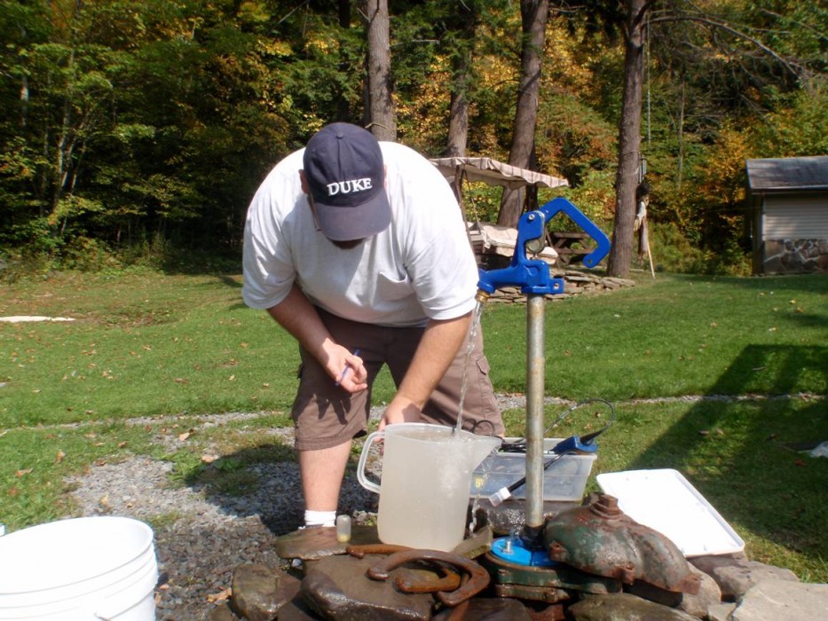
Pour pea gravel between the casing and the dirt. Next, mix the concrete and pour between the ground and casing. This will prevent the well from becoming contaminated from runoff. Once this is complete and you’ve added a well pump, you’ll need to run the well for a couple of days until the water is clear, and it’s always a good idea to get the water tested before using it for drinking.
Drilling a well can be a long process, but if you can save money and learn a new skill at the same time, why not give it a try? It’s a matter of getting back to basics and doing more for yourself.
Carole West is a freelance writer, photographer, author, and founder of the blog Garden Up Green. She lives in the north Texas countryside with her husband, Robert. They live a peaceful life where they spend most of their time establishing Quail Grove, a tiny homestead community.

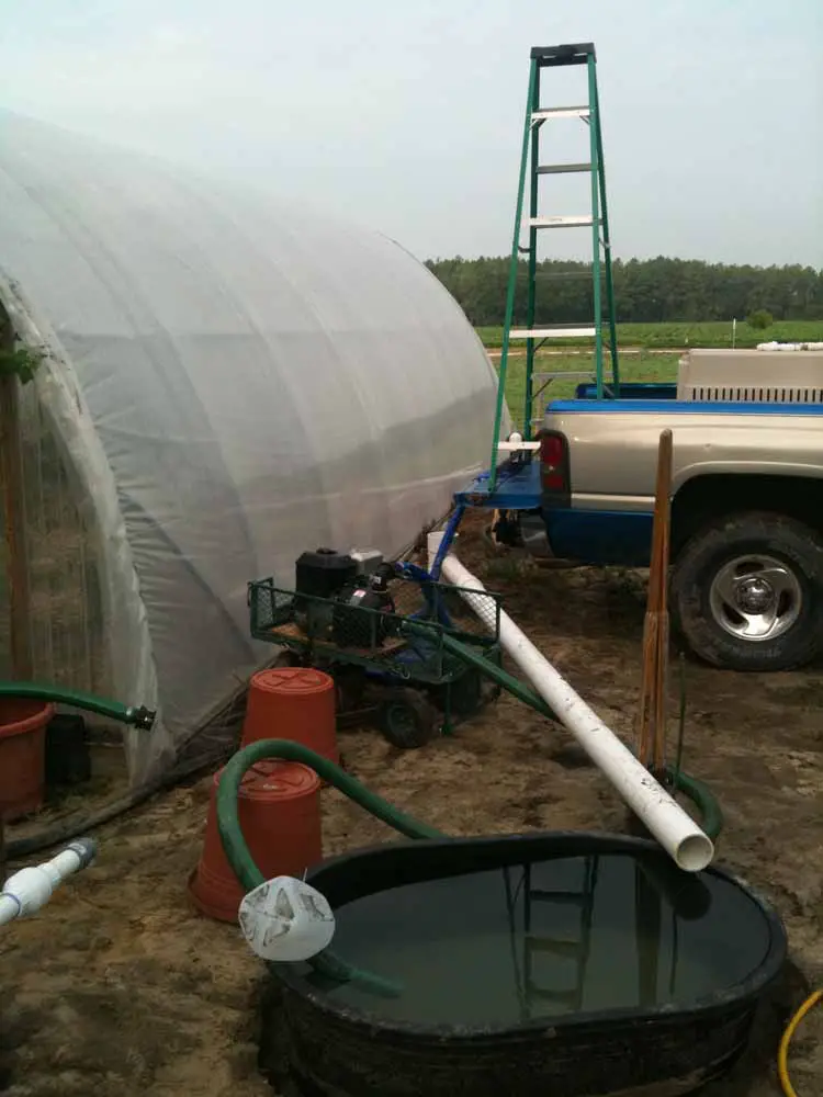
more at http://www.drillyourownwell.com This is an example of a Mud Pump Water Well Drilling Setup utilizing a Portable Mud pit. This particular well was ...

This is our new Terragrinder deluxe ready-to-drill kit! It contains everything you need to buy from us to drill your well, and it is available now for only a fraction of the cost of other well drilling kits on the market!
When choosing a size and type of mud pump for your drilling project, there are several factors to consider. These would include not only cost and size of pump that best fits your drilling rig, but also the diameter, depth and hole conditions you are drilling through. I know that this sounds like a lot to consider, but if you are set up the right way before the job starts, you will thank me later.
Recommended practice is to maintain a minimum of 100 to 150 feet per minute of uphole velocity for drill cuttings. Larger diameter wells for irrigation, agriculture or municipalities may violate this rule, because it may not be economically feasible to pump this much mud for the job. Uphole velocity is determined by the flow rate of the mud system, diameter of the borehole and the diameter of the drill pipe. There are many tools, including handbooks, rule of thumb, slide rule calculators and now apps on your handheld device, to calculate velocity. It is always good to remember the time it takes to get the cuttings off the bottom of the well. If you are drilling at 200 feet, then a 100-foot-per-minute velocity means that it would take two minutes to get the cuttings out of the hole. This is always a good reminder of what you are drilling through and how long ago it was that you drilled it. Ground conditions and rock formations are ever changing as you go deeper. Wouldn’t it be nice if they all remained the same?
Centrifugal-style mud pumps are very popular in our industry due to their size and weight, as well as flow rate capacity for an affordable price. There are many models and brands out there, and most of them are very good value. How does a centrifugal mud pump work? The rotation of the impeller accelerates the fluid into the volute or diffuser chamber. The added energy from the acceleration increases the velocity and pressure of the fluid. These pumps are known to be very inefficient. This means that it takes more energy to increase the flow and pressure of the fluid when compared to a piston-style pump. However, you have a significant advantage in flow rates from a centrifugal pump versus a piston pump. If you are drilling deeper wells with heavier cuttings, you will be forced at some point to use a piston-style mud pump. They have much higher efficiencies in transferring the input energy into flow and pressure, therefore resulting in much higher pressure capabilities.
Piston-style mud pumps utilize a piston or plunger that travels back and forth in a chamber known as a cylinder. These pumps are also called “positive displacement” pumps because they literally push the fluid forward. This fluid builds up pressure and forces a spring-loaded valve to open and allow the fluid to escape into the discharge piping of the pump and then down the borehole. Since the expansion process is much smaller (almost insignificant) compared to a centrifugal pump, there is much lower energy loss. Plunger-style pumps can develop upwards of 15,000 psi for well treatments and hydraulic fracturing. Centrifugal pumps, in comparison, usually operate below 300 psi. If you are comparing most drilling pumps, centrifugal pumps operate from 60 to 125 psi and piston pumps operate around 150 to 300 psi. There are many exceptions and special applications for drilling, but these numbers should cover 80 percent of all equipment operating out there.
The restriction of putting a piston-style mud pump onto drilling rigs has always been the physical size and weight to provide adequate flow and pressure to your drilling fluid. Because of this, the industry needed a new solution to this age-old issue.
Enter Cory Miller of Centerline Manufacturing, who I recently recommended for recognition by the National Ground Water Association (NGWA) for significant contributions to the industry.
As the senior design engineer for Ingersoll-Rand’s Deephole Drilling Business Unit, I had the distinct pleasure of working with him and incorporating his Centerline Mud Pump into our drilling rig platforms.
In the late ’90s — and perhaps even earlier — Ingersoll-Rand had tried several times to develop a hydraulic-driven mud pump that would last an acceptable life- and duty-cycle for a well drilling contractor. With all of our resources and design wisdom, we were unable to solve this problem. Not only did Miller provide a solution, thus saving the size and weight of a typical gear-driven mud pump, he also provided a new offering — a mono-cylinder mud pump. This double-acting piston pump provided as much mud flow and pressure as a standard 5 X 6 duplex pump with incredible size and weight savings.
The true innovation was providing the well driller a solution for their mud pump requirements that was the right size and weight to integrate into both existing and new drilling rigs. Regardless of drill rig manufacturer and hydraulic system design, Centerline has provided a mud pump integration on hundreds of customer’s drilling rigs. Both mono-cylinder and duplex-cylinder pumps can fit nicely on the deck, across the frame or even be configured for under-deck mounting. This would not be possible with conventional mud pump designs.
Centerline stuck with their original design through all of the typical trials and tribulations that come with a new product integration. Over the course of the first several years, Miller found out that even the best of the highest quality hydraulic cylinders, valves and seals were not truly what they were represented to be. He then set off on an endeavor to bring everything in-house and began manufacturing all of his own components, including hydraulic valves. This gave him complete control over the quality of components that go into the finished product.
The second generation design for the Centerline Mud Pump is expected later this year, and I believe it will be a true game changer for this industry. It also will open up the application to many other industries that require a heavier-duty cycle for a piston pump application.

There are many different ways to drill a domestic water well. One is what we call the “mud rotary” method. Whether or not this is the desired and/or best method for drilling your well is something more fully explained in this brief summary.
One advantage of drilling with compressed air is that it can tell you when you have encountered groundwater and gives you an indication how much water the borehole is producing. When drilling with water using the mud rotary method, the driller must rely on his interpretation of the borehole cuttings and any changes he can observe in the recirculating fluid. Mud rotary drillers can also use borehole geophysical tools to interpret which zones might be productive enough for your water well.
The mud rotary well drilling method is considered a closed-loop system. That is, the mud is cleaned of its cuttings and then is recirculated back down the borehole. Referring to this drilling method as “mud” is a misnomer, but it is one that has stuck with the industry for many years and most people understand what the term actually means.
The water is carefully mixed with a product that should not be called mud because it is a highly refined and formulated clay product—bentonite. It is added, mixed, and carefully monitored throughout the well drilling process.
The purpose of using a bentonite additive to the water is to form a thin film on the walls of the borehole to seal it and prevent water losses while drilling. This film also helps support the borehole wall from sluffing or caving in because of the hydraulic pressure of the bentonite mixture pressing against it. The objective of the fluid mixture is to carry cuttings from the bottom of the borehole up to the surface, where they drop out or are filtered out of the fluid, so it can be pumped back down the borehole again.
When using the mud rotary method, the driller must have a sump, a tank, or a small pond to hold a few thousand gallons of recirculating fluid. If they can’t dig sumps or small ponds, they must have a mud processing piece of equipment that mechanically screens and removes the sands and gravels from the mixture. This device is called a “shale shaker.”
The fluid mixture must have a gel strength sufficient to support marble-size gravels and sand to the surface when the fluid is moving. Once the cuttings have been carried to the surface and the velocity of the fluid allowed to slow down, the fluid is designed to allow the sand and gravel to drop out.
The driller does not want to pump fine sand through the pump and back down the borehole. To avoid that, the shale shaker uses vibrating screens of various sizes and desanding cones to drop the sand out of the fluid as it flows through the shaker—so that the fluid can be used again.
When the borehole has reached the desired depth and there is evidence that the formation it has penetrated will yield enough water, then it’s time to make the borehole into a well.
Before the well casing and screens are lowered into the borehole, the recirculating fluid is slowly thinned out by adding fresh water as the fluid no longer needs to support sand and gravel. The driller will typically circulate the drilling from the bottom up the borehole while adding clear water to thin down the viscosity or thickness of the fluid. Once the fluid is sufficiently thinned, the casing and screens are installed and the annular space is gravel packed.
Gravel pack installed between the borehole walls and the outside of the well casing acts like a filter to keep sand out and maintain the borehole walls over time. During gravel packing of the well, the thin layer of bentonite clay that kept the borehole wall from leaking drilling fluid water out of the recirculating system now keeps the formation water from entering the well.
This is where well development is performed to remove the thin bentonite layer or “wall cake” that was left behind. Various methods are used to remove the wall cake and develop the well to its maximum productivity.
Some drillers use compressed air to blow off the well, starting at the first screened interval and slowly working their way to the bottom—blowing off all the water standing above the drill pipe and allowing it to recover, and repeating this until the water blown from the well is free of sand and relatively clean. If after repeated cycles of airlift pumping and recovery the driller cannot find any sand in the water, it is time to install a well development pump.
Additional development of the well can be done with a development pump that may be of a higher capacity than what the final installation pump will be. Just as with cycles of airlift pumping of the well, the development pump will be cycled at different flow rates until the maximum capacity of the well can be determined. If the development pump can be operated briefly at a flow rate 50% greater than the permanent pump, the well should not pump sand.
Mud rotary well drillers for decades have found ways to make this particular system work to drill and construct domestic water wells. In some areas, it’s the ideal method to use because of the geologic formations there, while other areas of the country favor air rotary methods.
Some drilling rigs are equipped to drill using either method, so the contractor must make the decision as to which method works best in your area, for your well, and at your point in time.
To learn more about the difference between mud rotary drilling and air rotary drilling, click the video below. The video is part of our “NGWA: Industry Connected” YouTube series:
Gary Hix is a Registered Professional Geologist in Arizona, specializing in hydrogeology. He was the 2019 William A. McEllhiney Distinguished Lecturer for The Groundwater Foundation. He is a former licensed water well drilling contractor and remains actively involved in the National Ground Water Association and Arizona Water Well Association.
To learn more about Gary’s work, go to In2Wells.com. His eBooks, “Domestic Water Wells in Arizona: A Guide for Realtors and Mortgage Lenders” and “Shared Water Wells in Arizona,” are available on Amazon.
Plan for the best and be ready to take corrective actions when your plans go wrong! This section of the tutorial is designed to help you solve the problems you will encounter when you drill wells. Don"t be discouraged.... use your common sense and learn what you can from the situation you are in! Common problems include:
Large amounts of make-up water is usually required and must be immediately available at all times when drilling in permeable sand and gravel. This is important because drilling fluid sometimes suddenly flows into permeable
If return circulation is suddenly lost, immediately switch the 3-way valve to direct the drilling fluid back to the pit through the by-pass hose (this minimizes the loss of valuable water). Then quickly pull-up the drill pipe 1-2 metres from the bottom of the borehole so that it is less likely to become jammed if the bottom portion of the hole collapses.
(Australian, 1992). A waiting period may allow the fluid to gel in the formation and provide a seal sufficient to allow circulation to be restored. If drilling has been proceeding with water or natural mud, replace the fluid with a thick bentonite slurry, circulate it down the borehole and let it sit for a while. When ready to circulate back
If waiting and thickening the drilling mud do not restore circulation, question why the circulation was lost. If the drilling fluid is being lost into a highly permeable saturation formation, it may be possible to construct an excellent well! Therefore, test the well yield before deciding to proceed with the steps outlined below.
If it is necessary to drill further, try adding thickening materials to the drilling mud. This may occur when extremely unstable formations or those containing open fractures are encountered. Almost any granular flake or fibrous material can be used to provide a wad to block a lost circulation zone. Local materials such as bran, husks, chaff, straw, bark, wood chips, cotton, feathers, or even fibre or wool bedding can usually be located readily and used (Australian, 1992). This material should be pushed down the hole and allowed
The "gunk squeeze" method of sealing off a zone of lost circulation involves forcing a large amount of clay or cement into the zone of water loss (usually at or near the drill bit) and forcing it into the formation where it swells and fills-up any cracks (Australian, 1992). The best way is to mix a very high concentration (6 - 7 kg/L) of bentonite. Once mixed, immediately lower it into the borehole in a sealed bag or container which can be ruptured when opposite the lost circulation zone. This material can be forced into the formation by pressurizing the borehole or by pushing it with a block on the end of the drill string.
If the lost circulation zone cannot be blocked, drilling sometimes may proceed without return circulation. The cuttings are carried away into the formation cavities. It may be necessary to occasionally pump a slug of thick mud to clear the bottom of the hole (Australian, 1992).
Alternatively, casing can be placed to seal-off the problem zone. Ensure that the hole has fully penetrated the problem zone which is to be protected by the casing; Running the casing too soon may not overcome the problems for long. Finally, if none of these options work, it may be necessary to abandon the hole or to continue drilling using a air rotary drilling machine (Australian, 1992).
The main cause of borehole caving is lack of suitable drilling mud (see Section 5). This often occurs in sandy soils where drillers are not using good bentonite or polymer. The problem can be seen when fluid is circulating but cuttings are not being carried-out of the hole. If you continue to push ahead and drill, the bit can become jammed, the hole will collapse when you try to insert the casing or a huge portion of the aquifer may wash-out making it very difficult to complete a good well. The solution is to get some bentonite or polymer or, if necessary, assess the suitability of natural clays for use as drill mud (see Appendix H).
Borehole caving can also occur if the fluid level in the borehole drops significantly (see Footnote #1). Therefore, following a loss of circulation or a night time stoppage, slowly re-fill the borehole by circulating drilling fluid through the drill pipe (pouring fluid directly into the borehole may trigger caving). If caving occurs while drilling, check if cuttings are still exiting the well. If they are, stop drilling and circulate drilling fluid for a while.
Sometimes part of the borehole caves while the casing is being installed, preventing it from being inserted to the full depth of the borehole. When this occurs, the casing must be pulled out and the well re-drilled with heavier drilling fluid. When pulling the casing, no more than 12.19 m (40 ft) should be lifted into the air at any time; more than this will cause thin-walled (Schedule 40) PVC to bend and crack.
The drill pipe and bit may become jammed when the drilling fluid is not allowed to thoroughly clean the borehole prior to stopping to add another joint of drilling pipe or the fluid is too thin to lift gravel from the bottom of the borehole.
Therefore, if the drill bit starts to catch when drilling, stop further drilling and allow the drilling fluid to circulate and remove accumulated cuttings from the borehole. Then continue to drill at a slower rate. If it continues to catch, thicken the drilling fluid.
If the drill bit and pipe become jammed, stop drilling and circulate drilling fluid until it is freed. If circulation is blocked, try to winch the bit and pipe out of the borehole. Stop the engine and use a pipe wrench to reverse rotation (no more than 1 turn or the rod may unscrew!). Rapidly hit the drill pipe with a hammer to try and jolt the bit free.
If these actions are not successful, use lengths of drill pipe without a bit attached or Wattera tubing to "jet out" the cuttings. Attach the pipe or tubing directly to the discharge hose from the mud pump. Thicken the drilling fluid to ensure that the cuttings holding the bit can be removed. Then place tension of the stuck pipe with the drill rig
winch. Once fluid starts to circulate out of the borehole, slowly push the jetting pipe/tubing down the borehole beside the jammed drill pipe until the bit is reached. When fluid starts to circulate out of the stuck pipe and/or it loosens, pull the stuck drill pipe and resume circulation of the thickened drilling fluid back down the drill pipe and bit. Remove the jetting pipe. If water freely circulates out the borehole, slowly lower the drill pipe and bit and resume drilling.
Unfortunately, sometimes wrenches, rocks etc are inadvertently dropped into the borehole when drilling. In addition, the LS-100 is often operated near its design limits with a high degree of structural stress on the drilling stems
and tools; encountering unexpected layers of very soft sand or filter or hard rock can cause cave-ins or tool breakage and all the drill pipe can be lost in the hole.
If objects are dropped into the borehole after the final depth has been reached, it may be possible to leave them there and still complete the well. If this is not the case, it may be possible to make a "fishing" tool to set-up on the lost gear. For example, if a length of well screen falls down the borehole, it may be possible to send other sections down with a pointed tip on the end and "catch" the lost casing by cramming the pointed end hard into it. These types of "fishing" exercises require innovation and resourcefulness suitable to the circumstances - there is no single right way of doing this work. If sediment has caved in on top of the drill bit or other tools, circulation should be resumed in the hole and the fishing tool placed over the lost equipment.
If the lost tools/bit(s)/drill pipe are not critical, do not even try to retrieve them and just move over and start drilling a new hole. Even if the equipment is important, it is still best to start drilling at a new location while others try to retrieve it since considerable time can be spent on retrieval and there is a low likelihood of success.G-6: Resistant Beds Encountered
Once a resistant bed is encountered and the rate at which the drill bit is penetrating the formation drops dramatically, a decision needs to be made whether to stop drilling or to continue. If the resistant bed is comprised of gravels, the drilling fluid may need to be thickened to lift-out the cuttings. If the resistant bed is hard granite, drilling with the LS-100 should cease. Other drilling methods should be found or drilling should be attempted at another location. Remember, to help as many people as possible and to get the best value for donor dollars, DRILL THE EASY BOREHOLES FIRST!! It is not worth wearing-out the equipment by grinding away for hours and hours to gain a foot or two of borehole depth.
It is sometimes necessary to drill through aquifers which contain contaminated water. In these situations, drill until a confining layer (clay or rock) is encountered. Insert the casing and then seal the annular space with a grout slurry. To avoid damaging the grout seal, let the grout cure for at least 12-24 hours prior to resuming drilling
Grout is prepared by mixing 19.7 L (5.2 gal) of water with every 42.6 kg (94 lb) sack of cement (Driscoll, 1986); 5 volumes grout slurry can be made by mixing 4 volumes cement powder with 3 volumes fresh water (Australian, 1992). Alternatively, each sack of cement can be added to a clay-water suspension formed by mixing 1.36 - 2.27 kg (3-5 lbs) of bentonite with 25 L (6.5 gal) of water (Driscoll, 1986). This mixture helps hold cement particles in suspension, reduces cement shrinkage, improves the fluidity of the mixture and prevents excessive penetration of grout into these formations.
Cement grout is normally placed by just pouring it into the annulus. Alternatively, some grout could also be poured into the casing and/or the casing could be raised several feet and then pushed into the grout that accumulates at the bottom of the borehole. Place the grout in one continuous operation to form a good seal (Driscoll, 1986). Since irregularities in the size of the borehole and losses into formation may occur, the driller must be prepared to augment initial estimates of grout volume on short notice.
Sometimes the water in a confined aquifer is under so much pressure that it will flow out the top of a well which is drilled into it. Special precautions and construction techniques must be used to control the water pressure and flow or serious environmental problems can result. The free flow of excess water to waste can result in the depletion of a valuable resource and in unnecessary interference with other well supplies. Free flow from the well casing or a breakout of uncontrolled flow around the well casing can cause serious erosional and flooding problems on the owner"s and adjacent properties that may be very difficult and costly to correct.
Sometimes natural flow can be brought under control by extending the well casing 1.5 - 6 m (5 - 20 ft) into the air. This can allow the pressure in the pipe to balance that within the aquifer. A spout with a tap can then be installed in the side of the casing. A hand pump can be installed at a later date if the pressure in the pipe drops over time.
Sometimes a very thin or relatively impermeable aquifer is encountered which must be developed to provide a reliable water supply. Ensure that the borehole penetrates the full thickness of the aquifer, extending as far below it as possible. Install the well screen adjacent to the entire aquifer thickness with solid casing installed above and below it. After developing the well, install the pump cylinder as low as possible in the well.
If a well is being completed in a fine sand/silt aquifer within 15-22 m (50 - 75 ft) of ground surface, a 20 cm (8 in) reamer bit has sometimes been used (e.g. Bolivia). This makes it possible to install a better filter pack and reduces entrance velocities and passage of fine silt, clay and sand particles into the well.
Yield can be maximized by adding a small amount of a polyphosphate to the well after it has been developed using conventional techniques. The polyphosphate helps remove clays that occur naturally in the aquifer and that were introduced in the drilling fluid (see Footnote #3).
Enough time must be allowed between introduction of the polyphosphate and development, usually overnight, so the clay masses become completely desegregated (Driscoll, 1986). After the polyphosphate solution is surged into the screen (see Footnote #4), water should be added to the well to drive the solution farther into the formation.
Sometimes it is not possible to lower the casing and well screen to the bottom of the hole. This can be due to part of the borehole collapsing, clays in the aquifer swelling and reducing the size of the borehole or the borehole being crooked resulting in the casing digging into the wall of the borehole. These problems are most common where 10 cm (4 in) schedule 40 casing is being inserted into a 15 cm (6 in) borehole. This is because the outside diameter of the casing couplers is 13 cm (5.25 in), leaving an annular space of just over a quarter inch on each side of the casing! It does not take much swelling of clays or slight deviation from vertical to result in the casing jamming.
If the casing does not slide freely into the borehole, it is not advisable to try and force the casing down. Striking it hard in an attempt to drive it may cause the screen to deform; rotating and pushing it down can cause the screen openings to become hopelessly plugged with fine materials.
To avoid these problems, minimize the amount of pull-down pressure when drilling so that the bit can run freely under its own weight. Also, casing there is no problem with casing jambing when 7.6 cm (3 in) schedule 40 casing is used. Keep in mind, however, that a 7.6 cm (3 in) casing is too small to take a 6.4 cm (2.5 in) pump cylinder or most submersible pumps. Usually, however, these issues are not a concern.
If you need to construct a 10 cm (4 in) well and the casing has jammed, the best solution is to pull the casing / screen from the borehole. This involves cutting the casing into 6-12 m (20 - 40 ft) lengths (longer than this will result in the casing bending and cracking). Slowly re-drill the borehole with a 15 cm (6 in) reamer bit or, if available, a 18 or 20 cm (7 or 8 in) bit. Concentrate on the portion of the borehole where the casing jammed. While this can take several hours, it often eliminates blockages and allows the casing to slide to the bottom of the borehole. As soon as the reaming is completed, re-glue and re-insert the casing.
If it still jams, your last resort is to try and "wash" the casing down by installing the drilling rods down inside the casing and circulating drilling fluid through a wash-down valve (see Section 7). Fluid is pumped down through the casing and out the bottom of the screen where it will pick-up and carry soil particles back up to the surface between the casing and the hole walls. The amount of water passing through the screen openings can be minimized by attaching a surge block to the lower end of the drill string. Be sure to secure the pipe with a rope to prevent the casing from dropping if the blockage was localized and is removed with the circulation process. Failure to do so could result in the casing dropping to the bottom of the hole without the casing extending to the surface. When the casing is finally installed to the appropriate depth, stabilize the open bottom
end of the casing by pouring in 30-60 cm of coarse gravel into the well. If the casing still jams above the water bearing formation, the only other option is to obtain and install 7.6 cm (3 in) casing and well screen.
A well can suddenly no longer provide the same amount of water that it did before. If you move the pump handle and it feels OK but little or no water comes out the spout, the well may be dry. Confirm this by measuring the water level in the well and try to determine which of the following causes is responsible:
Natural Lowering of the Water Table: Water levels in shallow dug and bored wells experience large fluctuations due to climatic conditions. The natural seasonal change in water level often will often be several metres. This is likely the cause of the drop in yield if the level of water within the well does not rise up, even several hours after pumping. All that can be done is to construct a new well, ensuring that the well casing is set far enough below the water table (ideally 5 to 10 metres) to assure an adequate water supply during the dry summer periods when the water level declines. Also, check how many people are drawing water from the
Well Water Interference: The construction of water and sewer mains, drainage ditches and highways (road cuts) can occasionally affect ground-water levels and interfere with nearby shallow wells. In addition, the static water level in a well may be affected by large withdrawals of ground water from nearby large capacity wells or de-watering equipment for construction works (see Footnote #5). The potential for well interference depends greatly on the lithology of the producing formation and the magnitude of well usage.
Screen Blockage: Sometimes the problem is that the well screen has plugged-up with fine sand and silt particles, with accumulated iron deposits or with growths of nuisance bacteria (naturally occurring, non-health related bacteria with can produce rotten egg smells, random slugs of iron rich water etc). This is likely the case if the water level in the well is near its original construction level but drops to the bottom of the pump cylinder as soon as the well is pumped. The well should be extensively re-developed to try and restore the efficiency of the screen and gravel pack (see
1 The drilling fluid prevents caving of the borehole because it exerts pressure against the wall. As long as the hydrostatic pressure of the fluid exceeds the earth pressures and any confining pressure in the aquifer, the hole will remain open. The pressure at any depth is equal to the weight of the drilling fluid column above that point.
2 Before drilling out the grout plug, the effectiveness of the seal can be checked by measuring water-level change in the casing over time. In wells with a low static water level, the casing can be filled with water or drilling fluid and later checked for any water loss. If the static water level is high, the casing can be nearly emptied and any influx of water into the casing can be measured.
L (100 gal) of water in the screen. 0.9 kg (2 lbs) of sodium hypochlorite should also be added to every 100 gal of water in the well to control bacterial growth promoted by the presence of polyphosphates (Driscoll, 1986). Polyphosphates should be premixed before introduction into the well because they do not mix easily with cold water. Occasionally the mix water is heated to help dissolve the chemical (Driscoll, 1986). Polyphosphates should NOT be used in formations with thinly bedded clays and sands because these chemicals tend to make the clays near the borehole unstable, causing them to mix with the sand (Driscoll, 1986) continually passes into the borehole during pumping (Anderson, 1993).
5 When a well is pumped, the water level in the immediate area of the well is lowered and a cone of depression develops around the well. The size and the shape of the cone will depend on the aquifer characteristics of the water-bearing formation in which the well is completed and the rate of pumping. This is likely the cause if there are two or more wells located within 100 m of each other and if water levels return to normal in both wells once pumping has stopped or within some reasonable time afterwards. Water level recovery depends on the quantity of water withdrawn from the aquifer and the length of time the wells were pumped. All that can be done is
Australian Drilling Industry Training Committee Ltd (1992) Australian Drilling Manual 3rd edition", Macquarie Centre: Australian Drilling Industry Training Committee Ltd, ISBN 0-949279-20X.


 8613371530291