
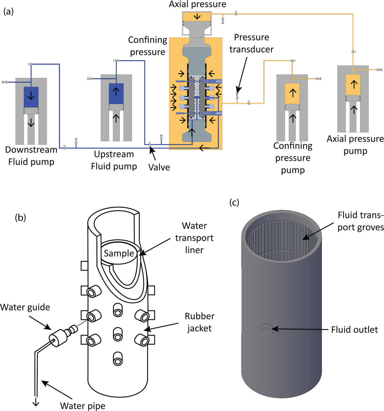
drilling mud pump pressure free sample

Cameron provides a range of integrated pump packages, including top- or rear-mount AC- or DC-electric drives, controls, manifolds, piping, and accessories for onshore and offshore applications.

The 2,200-hp mud pump for offshore applications is a single-acting reciprocating triplex mud pump designed for high fluid flow rates, even at low operating speeds, and with a long stroke design. These features reduce the number of load reversals in critical components and increase the life of fluid end parts.
The pump’s critical components are strategically placed to make maintenance and inspection far easier and safer. The two-piece, quick-release piston rod lets you remove the piston without disturbing the liner, minimizing downtime when you’re replacing fluid parts.

When choosing a size and type of mud pump for your drilling project, there are several factors to consider. These would include not only cost and size of pump that best fits your drilling rig, but also the diameter, depth and hole conditions you are drilling through. I know that this sounds like a lot to consider, but if you are set up the right way before the job starts, you will thank me later.
Recommended practice is to maintain a minimum of 100 to 150 feet per minute of uphole velocity for drill cuttings. Larger diameter wells for irrigation, agriculture or municipalities may violate this rule, because it may not be economically feasible to pump this much mud for the job. Uphole velocity is determined by the flow rate of the mud system, diameter of the borehole and the diameter of the drill pipe. There are many tools, including handbooks, rule of thumb, slide rule calculators and now apps on your handheld device, to calculate velocity. It is always good to remember the time it takes to get the cuttings off the bottom of the well. If you are drilling at 200 feet, then a 100-foot-per-minute velocity means that it would take two minutes to get the cuttings out of the hole. This is always a good reminder of what you are drilling through and how long ago it was that you drilled it. Ground conditions and rock formations are ever changing as you go deeper. Wouldn’t it be nice if they all remained the same?
Centrifugal-style mud pumps are very popular in our industry due to their size and weight, as well as flow rate capacity for an affordable price. There are many models and brands out there, and most of them are very good value. How does a centrifugal mud pump work? The rotation of the impeller accelerates the fluid into the volute or diffuser chamber. The added energy from the acceleration increases the velocity and pressure of the fluid. These pumps are known to be very inefficient. This means that it takes more energy to increase the flow and pressure of the fluid when compared to a piston-style pump. However, you have a significant advantage in flow rates from a centrifugal pump versus a piston pump. If you are drilling deeper wells with heavier cuttings, you will be forced at some point to use a piston-style mud pump. They have much higher efficiencies in transferring the input energy into flow and pressure, therefore resulting in much higher pressure capabilities.
Piston-style mud pumps utilize a piston or plunger that travels back and forth in a chamber known as a cylinder. These pumps are also called “positive displacement” pumps because they literally push the fluid forward. This fluid builds up pressure and forces a spring-loaded valve to open and allow the fluid to escape into the discharge piping of the pump and then down the borehole. Since the expansion process is much smaller (almost insignificant) compared to a centrifugal pump, there is much lower energy loss. Plunger-style pumps can develop upwards of 15,000 psi for well treatments and hydraulic fracturing. Centrifugal pumps, in comparison, usually operate below 300 psi. If you are comparing most drilling pumps, centrifugal pumps operate from 60 to 125 psi and piston pumps operate around 150 to 300 psi. There are many exceptions and special applications for drilling, but these numbers should cover 80 percent of all equipment operating out there.
The restriction of putting a piston-style mud pump onto drilling rigs has always been the physical size and weight to provide adequate flow and pressure to your drilling fluid. Because of this, the industry needed a new solution to this age-old issue.
As the senior design engineer for Ingersoll-Rand’s Deephole Drilling Business Unit, I had the distinct pleasure of working with him and incorporating his Centerline Mud Pump into our drilling rig platforms.
In the late ’90s — and perhaps even earlier — Ingersoll-Rand had tried several times to develop a hydraulic-driven mud pump that would last an acceptable life- and duty-cycle for a well drilling contractor. With all of our resources and design wisdom, we were unable to solve this problem. Not only did Miller provide a solution, thus saving the size and weight of a typical gear-driven mud pump, he also provided a new offering — a mono-cylinder mud pump. This double-acting piston pump provided as much mud flow and pressure as a standard 5 X 6 duplex pump with incredible size and weight savings.
The true innovation was providing the well driller a solution for their mud pump requirements that was the right size and weight to integrate into both existing and new drilling rigs. Regardless of drill rig manufacturer and hydraulic system design, Centerline has provided a mud pump integration on hundreds of customer’s drilling rigs. Both mono-cylinder and duplex-cylinder pumps can fit nicely on the deck, across the frame or even be configured for under-deck mounting. This would not be possible with conventional mud pump designs.
The second generation design for the Centerline Mud Pump is expected later this year, and I believe it will be a true game changer for this industry. It also will open up the application to many other industries that require a heavier-duty cycle for a piston pump application.

I’ve run into several instances of insufficient suction stabilization on rigs where a “standpipe” is installed off the suction manifold. The thought behind this design was to create a gas-over-fluid column for the reciprocating pump and eliminate cavitation.
When the standpipe is installed on the suction manifold’s deadhead side, there’s little opportunity to get fluid into all the cylinders to prevent cavitation. Also, the reciprocating pump and charge pump are not isolated.
The gas over fluid internal systems has limitations too. The standpipe loses compression due to gas being consumed by the drilling fluid. In the absence of gas, the standpipe becomes virtually defunct because gravity (14.7 psi) is the only force driving the cylinders’ fluid. Also, gas is rarely replenished or charged in the standpipe.
The suction stabilizer’s compressible feature is designed to absorb the negative energies and promote smooth fluid flow. As a result, pump isolation is achieved between the charge pump and the reciprocating pump.
The isolation eliminates pump chatter, and because the reciprocating pump’s negative energies never reach the charge pump, the pump’s expendable life is extended.
Investing in suction stabilizers will ensure your pumps operate consistently and efficiently. They can also prevent most challenges related to pressure surges or pulsations in the most difficult piping environments.
Sigma Drilling Technologies’ Charge Free Suction Stabilizer is recommended for installation. If rigs have gas-charged cartridges installed in the suction stabilizers on the rig, another suggested upgrade is the Charge Free Conversion Kits.

Bourgoyne, A.J.T., Chenevert , M.E. & Millheim, K.K., 1986. SPE Textbook Series, Volume 2: Applied Drilling Engineering, Society of Petroleum Engineers.
This invention relates to communication systems, and more particularly, to systems and methods for receiving and interpreting data signals being transmitted to the surface of the earth in a logging-while-drilling system.
Logging-while-drilling (LWD) or measurement-while-drilling (MWD) involves the transmission to the earth"s surface of downhole measurements taken during drilling. The measurements are generally taken by instruments mounted within drill collars above the drill bit. Indications of the measurements must then be transmitted uphole to the earth"s surface. Various schemes have been proposed for achieving transmission of measurement information to the earth"s surface. For example, one proposed technique transmits logging measurements by means of insulated electrical conductors extending through the drill string. This scheme, however, requires adaptation of drill string pipes including expensive provision for electrical connections at the drill pipe couplings. Another proposed scheme employs an acoustic wave that is generated downhole and travels upward through the metal drill string; but the high levels of interfering noise in a drill string are a problem in this technique.
The most common scheme for transmitting measurement information utilizes the drilling fluid within the borehole as a transmission medium for acoustic waves modulated to represent the measurement information. Typically, drilling fluid or "mud" is circulated downward through the drill string and drill bit and upward through the annulus defined by the portion of the borehole surrounding the drill string. The drilling fluid not only removes drill cuttings and maintains a desired hydrostatic pressure in the borehole, but cools the drill bit. In a species of the technique referred to above, a downhole acoustic transmitter known as a rotary valve or "mud siren", repeatedly interrupts the flow of the drilling fluid, and this causes a varying pressure wave to be generated in the drilling fluid at a frequency that is proportional to the rate of interruption. Logging data is transmitted by modulating the acoustic carrier as a function of the downhole measured data.
One difficulty in transmitting measurement information via the drilling mud is that the signal received is typically of low amplitude relative to the noise generated by the mud pumps which circulate the mud, as the downhole signal is generated remote from the uphole sensors while the mud pumps are close to the uphole sensors. In particular, where the downhole tool generates a pressure wave that is phase modulated to encode binary data, such as is disclosed in U.S. Pat. No. 4,847,815 and assigned to the assignee hereof, and where the periodic noise sources are at frequencies which are at or near the frequency of the carrier wave (e.g. 12 Hz), difficulties arise.
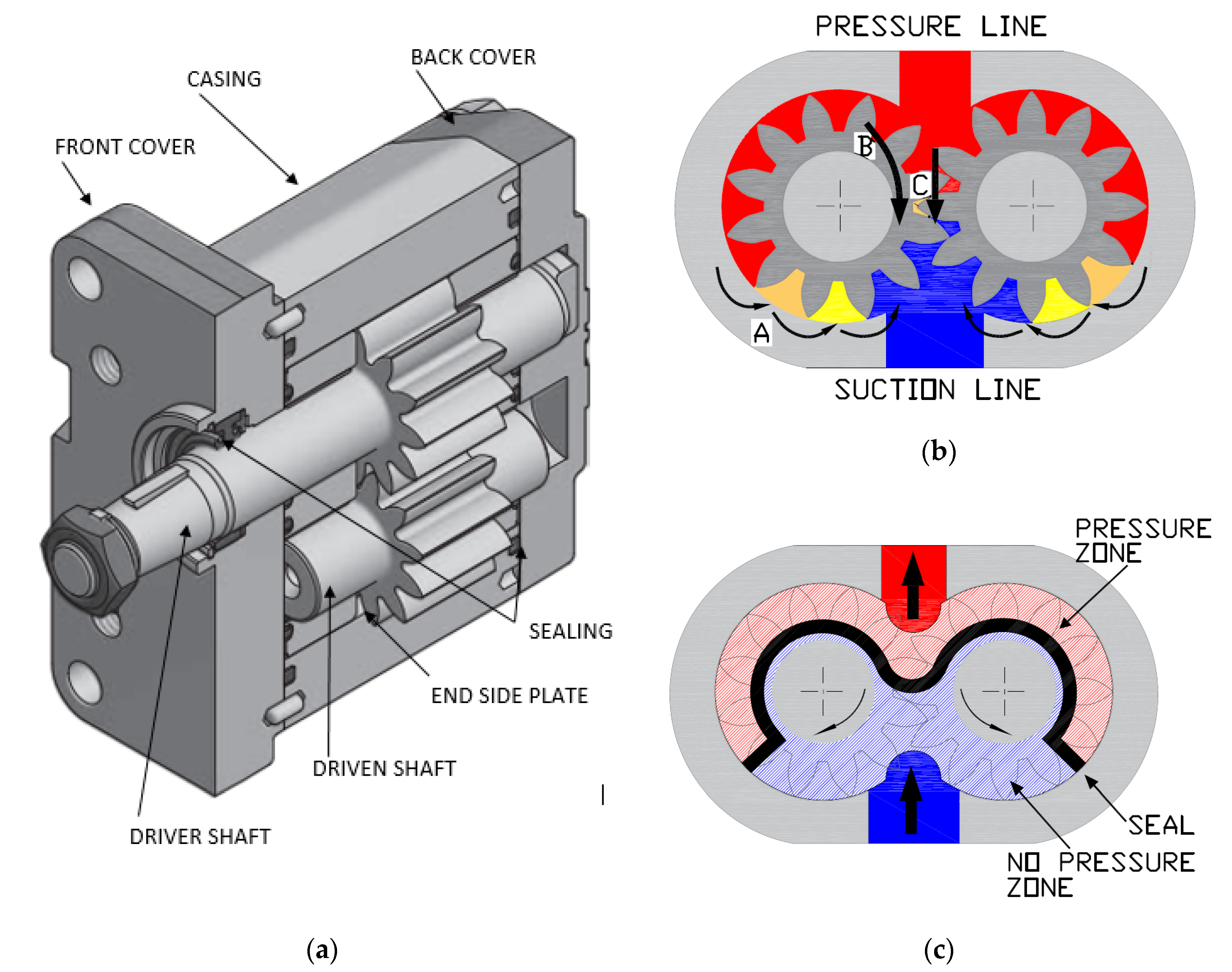
Mud pumps are large positive displacement pumps which generate flow by moving a piston back and forth within a cylinder while simultaneously opening and closing intake and exhaust valves. A mud pump typically has three pistons attached to a common drive shaft. These pistons are one hundred and twenty degrees out of phase with one another to minimize pressure variations. Mud pump noise is caused primarily by pressure variations while forcing mud through the exhaust valve.
The fundamental frequency in Hertz of the noise generated by the mud pumps is equal to the strokes per minute of the mud pump divided by sixty. Due to the physical nature and operation of mud pumps, harmonics are also generated, leading to noise peaks of varying amplitude at all integer values of the fundamental frequency. The highest amplitudes generally occur at integer multiples of the number of pistons per pump times the fundamental frequency, e.g., 3F, 6F, 9F, etc. for a pump with three pistons.
Mud pumps are capable of generating very large noise peaks if pump pressure variations are not dampened. Thus, drilling rigs are typically provided with pulsation dampeners at the output of each pump. Despite the pulsation dampeners, however, the mud pump noise amplitude is typically much greater than the amplitude of the signal being received from the downhole acoustic transmitter. To reduce or eliminate the mud pump noise so that the downhole signal can be recovered, different techniques have been proposed, such as may be found in U.S. Pat. Nos. 3,488,629 to Claycomb, 3,555,504 to Fields, 3,716,830 to Garcia, 4,215,425 to Waggener, 4,215,427 to Waggener et al., 4,262,343 to Claycomb, 4,590,593 to Rodney, and 4,642,800 to Umeda. What is common to all of the techniques is that they try to eliminate the mud pump noise by adding the mud pump noise to an inverted version of itself. Most of the techniques utilize two sensors in the mud stream (usually two pressure sensors) and take the difference of signals in an attempt to cancel the mud pump noise without canceling the data signal. Various of the techniques require particular physical arrangements.
The Umeda U.S. Pat. No. 4,642,800 takes a slightly different approach to eliminating mud pump noise. Umeda teaches that an average pump signature may be found by obtaining the pump signatures in the presence of data over a certain number of pump cycles. The updated average pump signature is corrected by interpolation to match the current pump cycle length and is subtracted from the current pump signature to provide the residual data signal. While the technique disclosed in Umeda may be effective for particular arrangements, it has several drawbacks. First, because Umeda averages pump signatures which include data pulses, unless the effect of the data signal over any averaging period is zero (i.e. non-carrier frequency systems), the data signal which is to be recovered will tend to be undesirably subtracted from itself. Second, because Umeda uses only a single strobe per pump cycle, estimates (e.g. interpolations) are utilized which can introduce significant error. Third, Umeda does not disclose in detail how to treat a multi-pump system. In particular, if Umeda assumes that the pump signature for each pump of a multi-pump system is the same as it would be for a single pump system, large errors are introduced in attempting to cancel out the pump noise, as pumps which are working in multi-pump systems will have different signatures than they would it they were working in a single pump system. In addition, because estimates are required for each pump in the multi-pump system, additional error in the multi-pump system is introduced.
It is therefore an object of the invention to provide methods and systems for accurately recovering data signals introduced into drilling mud in the presence of mud pump noise.
It is another object of the invention to provide methods and systems for accurately recovering logging-while-drilling (LWD) or measurement-while-drilling (MWD) information which is modulated in drilling mud by correlating mud pump piston positions to a mud pressure signature in a calibration procedure.
It is a further object of the invention to provide methods and systems for accurately obtaining LWD or MWD information in multiple mud pump systems by allocating noise attributable to each mud pump and by tracking the mud pump piston position of each mud pump.
Another object of the invention is to provide method and systems for recovering LWD or MWD information transmitted through drilling mud by varying the pressure of the drilling mud regardless of the manner in which the information is coded.
In accord with the objects of the invention, methods for recovering a LWD or MWD data signal in the presence of mud pump noise are provided, and generally comprise calibrating the drilling mud pressure as a function of the mud pump piston position, and then tracking the piston position during transmission of the LWD or MWD data signal and using the calibration information to subtract out the mud pump noise. More particularly, calibration is accomplished in the absence of the LWD or MWD data signal to provide a correlation between mud pump piston position and the drilling mud pressure; i.e., the pressure signature as a function of mud pump piston position is obtained. Then, when the LWD or MWD data signal is being provided, the mud pump piston position is tracked such that the pressure due to the pump can be subtracted; i.e., by knowing the mud pump piston position, the pressure due to the mud pump is found and subtracted from the total received signal to provide the LWD or MWD signal. Where a plurality of mud pumps are used, calibration is accomplished by running the mud pumps together in the absence of the LWD or MWD data signal, and processing the received mud pressure signals in the Fourier domain to allocated respective portions of the mud pressure signals to respective mud pumps such that each mud pump is provided with a signature as a function of its own piston position. With the piston position of each mud pump being tracked, the sum of the mud pressure signals generated by the mud pumps based on their piston positions is subtracted from the total received signal to provide the LWD or MWD signal.
According to a preferred aspect of the invention, the calibration procedure is periodically repeated, e.g., each time additional pipe is added to the drill string, thereby eliminating the effects of depth and mud property variation on the system.
FIGS. 8a, 8b, and 8c are respectively the total pump signal, and the signals from pump one and pump two in the multiple pump system calibrated according to FIGS 7a and 7b.
Referring to FIG. 1, the operation of the present invention in a typical drilling arrangement is illustrated schematically. Drilling mud 10 is picked up from mud pit 11 by one or more mud pumps 12 which are typically of the piston reciprocating type. The mud 10 is circulated through mud line 13, down through the drill string 14, through the drill bit 15, and back to the surface of the formation via the annulus 16 between the drill stem and the wall of the well bore 29. Upon reaching the earth"s surface 31, the mud is discharged through line 17 back into the mud pit 11 where cuttings of rock or other well debris are allowed to settle out before the mud is recirculated.
A downhole pressure pulse signaling device 18 is incorporated in the drill string for transmission of data signals derived during the drilling operation by the measurement instrument package 19. Signaling device 18 may be of the valve or variable orifice type which generates pressure pulses in the drilling fluid by varying the speed of flow. A preferred signaling device which generates sinusoidal signals is disclosed in U.S. Pat. No. 4,847,815 assigned to the assignee hereof. Data signals are encoded in a desired form by appropriate electronic means in the downhole tool. Arrows 21, 22, and 23 illustrate the path taken by the pressure pulses provided by the downhole signaling device 18 under typical well conditions. Pump 12 also produces pressure pulses in the mud line 13 and these are indicated by arrows, 24, 25, 26 and 26a which also illustrate the flow of the mud through the annulus 16.
In order for the downhole pressure pulse signals to be recoverable at the surface, some means must be provided to remove or substantially eliminate the portion of the mud pressure signal due to the mud pumps. Subsystem 30, including pressure transducer 32, mud pump piston position sensors 34, and computer or processor 36, comprises such a means.
The preferred pressure transducer 32 of subsystem 30 is a piezoelectric pressure transducer which provides an analog signal which is preferably bandpass filtered by a filter (not shown) or by the computer 36. The preferred mud pump piston position sensor 34 may either comprise an LVDT which utilizes a linear position transducer, or an RVDT which utilizes a rotary position transducer. The LVDT, as shown in FIG. 2a, has an arm 40a, a rod 42a, and a linear position transducer 44a with leads 46a. Arm 40a is coupled to one of the piston rods 47 of the mud pump 12 as well as to rod 42a of the LVDT. Rod 42a moves coaxially within the linear position transducer 44a, which provides a high precision digital indication of the location of piston 48 in the mud pump 12. The RVDT, as shown in FIG. 2b, has an arm 40b, a cable 42b, and an encoder or rotary position transducer 44b with a spring loaded sheave takeup reel 45b. The RVDT also includes leads 46b. Arm 40b of the RVDT of FIG. 2b is coupled to one of the piston rods 47 of the mud pump 12 as well as to the cable 42b of the RBDT. As arm 40b moves with the pump piston rod 47, the cable 42b is let out or reeled onto the takeup reel 45b takeup reel. The rotation of the takeup reel 45b provides a high precision digital indication of the location of piston 48 in the mud pump 12.
Testing has shown that the drilling mud pressure generated by the mud pump 12 is determined by the position of the mud pump piston for a given set of operating conditions. FIG. 3 illustrates how mud pump piston position correlates to mud pump noise. By coupling the linear position transducer 44a or rotary position transducer 44b to the piston rod 47 of the mud pump, a calibration can be performed that measures the pressure generated as a function of piston position.
The preferred calibration procedure for correlating mud pressure generated as a function of piston position for a single mud pump system is seen in FIG. 4. After the pump noise stabilizes in the system, and before the LWD and MWD tool turns on (i.e. before the data signal starts), the signals output by the position sensor 34 and the signals output by the pressure transducer 32 which are bandpass filtered at 39 are preferably recorded at 52 as related position and pressure arrays 55, 57 in the computer (e.g. in computer memory). Preferably, approximately eight seconds of data (e.g., five to ten pump cycles) are accumulated. Then, averages of the pressure as a function of position are calculated (thereby reducing random pressure variations) at 58 to produced a single position vs. pump noise calibration array 59. Indications of the average calibration array or the inverse thereof are stored and used for canceling mud pump noise as is hereinafter described.
The noise cancellation procedure according to the invention is set forth in FIG. 5. Upon the turning on of the downhole tool and the transmission of LWD or MWD data (hereinafter referred to simply as LWD data for sake of brevity), the position sensor 34 and pressure transducer 32 continue to provide indications of piston location and mud pressure; except that the piston position data is used in real time to determine the electrical signal (based on the calibration array 59) which must be subtracted from the composite LWD/noise signal to cancel the noise component of the signal and leave only the LWD signal. Thus, as shown in FIG. 5, the position sensor signal is sampled at 62 (i.e. based on the position sensor signal, the average calibration array is accessed and a corresponding pump noise is provided), and the corresponding pump noise pressure 64 is subtracted at 66 from the real time sensed pressure 32 which was bandpass filtered at 67 to eliminate high frequency components. The difference between the real time sensed pressure and the pump noise pressure provides an indication of the LWD data signal 68.
Test results of a real time sensed pressure pump noise signal are seen in FIG. 6a, where the amplitude of the signal as expressed in dB (in 10 dB increments) is plotted versus the frequency expressed in Hz (in 4 Hz increments). As seen in FIG. 6a, the noise signal includes several peaks having amplitudes between -10 dB and 0 dB, and even includes a peak having an amplitude exceeding 10 dB. The noise signal of FIG. 6a was then subjected to the noise cancellation procedure of FIG. 5. The noise signal remaining after mud pump noise cancellation is seen in FIG. 6b, and shows that the calibration and noise cancellation procedures reduced noise considerably. In fact, the largest remaining noise peak found at about 5 Hz, has an amplitude of approximately -15 dB, which is more than 25 dB less than the largest peak seen in FIG. 6a prior to noise cancellation.
Turing to FIGS. 7, 7a and 7b, a flow chart of the mud pump calibration procedure for a system utilizing two mud pumps is seen. After the pump noise stabilizes in the system, and before the LWD tool turns on (i.e. before the data signal starts), the signals output by each position sensor 34a, 34b and the signal output by the pressure transducer 32 and filtered at 39 by a bandpass filter which measures composite pump noise are recorded as related position arrays 55a, 55b and pressure array 57 in the computer (e.g. in computer memory). Preferably, approximately twelve seconds of data are accumulated in computer memory at 52; FIG. 8a showing an example of the analog pressure signal which is digitized and stored as part of the array. A fast Fourier transform (FFT) of the composite pump noise signal is then conducted at 70 by the computer. As a result of the FFT, the amplitude and phase of all frequencies contained in the composite mud pump noise signal is obtained at 70 (see FIG. 9a). Utilizing the operating speed of each pump which can be computed from the position sensor of each mud pump, the fundamental frequency and harmonics for each pump are calculated at 72. The, at 75, the amplitude and phase information for each fundamental and harmonic frequency are extracted from the FFT and assigned to its source (i.e. a particular one of the mud pumps) to provide results as seen in FIGS. 9b and 9c. Taking an inverse Fourier transform of the frequency spectra of FIGS. 9b and 9c at 76a and 76b, signals attributable to each of the pumps are obtained as seen in FIGS. 8b and 8c. As indicated in FIG. 7b at 58a and 58b, the position of each mud pump position sensor is related to the mud pressure generated by the respective mud pump, and an average of the pressure as a function of position is calculated for each mud pump to produce two position vs. pump noise calibration arrays 59a and 59b. Indications of the average calibration arrays are stored in computer memory and used for canceling mud pump noise as is described above with reference to FIG. 10.
Referring now to FIG. 10, the noise cancellation procedure for a system using multiple mud pumps is seen. Upon the turning on of the downhole tool and the transmission of LWD data, the position sensors 34a and 34b and pressure transducer 32 continue to provide indications of piston location and mud pressure; except that the piston position data is used in real time to determine the electrical signal (based on the calibration arrays 59a and 59b) which must be subtracted from the composite LWD/noise signal to cancel the noise component of the signal and leave only the LWD signal. Thus, as shown in FIG. 10, the position sensor signals are sampled at 62a and 62b (i.e. based on the position sensor signals, the average calibration arrays 59a and 59b are accessed and corresponding pump noises are provided), and the corresponding pump noise pressures 64a and 64b are subtracted at 66 from the real time sensed pressure 32 which was bandpass filtered at 67 to eliminate high frequency components. The difference between the real time sensed pressure and the pump noise pressures provides an indication of the LWD data signal 68. That signal is then decoded according to techniques known in the art which are not part of the present invention.
Test results of a real time sensed pressure containing pump noise for two mud pumps is seen in FIG. 11a where amplitude is plotted against frequency. As seen in FIG. 11a, numerous noise peaks having amplitudes of -20 dB or higher are seen, with the largest peak of about -5 dB at 5 Hz. The pressure signal obtained after utilizing the calibration and noise cancellation steps of FIGS. 7 and 10 in order to substantially cancel mud pump noise from the signal of FIG. 10a is seen in FIG. 10b. As seen in FIG. 10b, the remaining noise is substantially reduced relative to the noise of FIG. 10a, with the largest peak of about -18 dB occurring at approximately 18 Hz.
There have been described and illustrated herein methods and apparatus for canceling mud pump noise in order to recover a logging while drilling signal. While particular embodiments of the invention have been described it is not intended that the the invention be limited exactly thereto, as it is intended that the invention be as broad in scope as the art will allow. Thus, while particular pressure transducers, position sensors, pump-types, computers, FFT programs, and the like have been disclosed, it will be appreciated that other equipment and programs can be utilized effectively. Similarly, while certain preferred data gathering time periods were disclosed prior to running the LWD or MWD tool, it will be appreciated that other time frames could be utilized. Also, while the invention was described with reference to LWD and MWD procedures, it will be appreciated that the terms LWD and MWD are intended to include any other data signaling procedure where data is transmitted in drilling mud in the presence of mud pump noise. Further, while the invention was disclosed with reference to systems utilizing one or two mud pumps, it will be appreciated that the teachings equally apply to systems utilizing additional mud pumps. All that is required is that the pressure signature of each mud pump relative to its piston position be obtained via transforming the total signal into the Fourier domain, dividing the Fourier response among the various mud pumps based on their fundamental and harmonic frequencies, and converting the responses back into respective pressure signatures. It will be understood, of course, that where two mud pumps are working in unison (i.e. at the same frequency), their signatures can be treated together. Therefore, it will be apparent to those skilled in the art that other changes and modifications may be made to the invention as described in the specification without departing from the spirit and scope of the invention as so claimed.

This invention relates to the recovery of core barrel samples from the bottom of an oil well where it is desired to seal the core barrel sample and maintain it under the pressure existing at the bottom of the well when the sample is brought to the surface of the well. The invention also provides for positive indication at the well surface that the outer barrel is locked in sealing position and that the valve at the bottom of the core barrel is closed.
The present invention relates to a pressure core barrel assembly for recovering a core at formation pressure and is specifically directed to improvements in the type of pressure core barrel described in U.S. Pat. No. 3,548,958 issued 12/27/70 to Blackwell and Rumble. In such a pressure core barrel assembly it is important to know that the pressure core barrel has been sealed at formation pressure before the barrel is raised to the surface. If it is not sealed the sample will not be representative of the actual conditions existing in the formation at the bottom of the well.
The present invention provides an improved pressure core barrel of the type generally described in the above Blackwell et al Pat. No. 3,548,958 which has a number of improved features. First, the outer barrel (containing within it the core barrel) which is to seal the assembly at formation pressure is positively latched in both the raised (coring) position and the lowered (sealing) position. The arrangement of parts also provides for positive hydraulic assist for moving the outer barrel downwardly during the sealing operation to overcome any friction present at the bottom of the well. This is accomplished by using full mud hydraulic pressure both for triggering the latching mechanism and also for driving the outer barrel downward. Additionally, this hydraulic pressure is not released until the outer barrel has traveled substantially completely to the bottom position. Another feature of the invention provides that the pressurizing gas valve is not opened until the outer barrel has been lowered essentially to the closed position and the core sealing valve is being operated. Another feature provides for spring loaded actuation of the core sealing valve to prevent damage to the valve actuating mechanism in the event of jamming thereof. Another feature of the invention provides for the use of heavy duty splines and locking dogs which permit locking in both the open and closed position and also the transmission of torque in both open and closed positions. Other detailed advantages and improvements in the present invention will be apparent from the following discussion.
FIG. 3 shows the sealed core barrel assembly mounted in a pressurized flushing system for flushing drilling mud from the core barrel assembly prior to the freezing of the assembly for sectioning and analysis.
FIG. 1 also shows ball 35 which has been pumped down into a valve seat 36 at the top of the hollow latch actuating cylinder 32. In normal operation, without the ball 35, the drilling mud passes down the axis of the core barrel through the hollow cylinder and down to the bottom of the core bit in accordance with standard coring practice. When the ball 35 is seated in the valve seat 36 the flow of drilling mud is interrupted and the pressure above the ball 35 increases tending to force the latch actuating cylinder 32 down. When the full diameter portions 34 of the latch actuating cylinder 32 have moved downwardly a sufficient amount to free the latch dogs for inward motion, these latch dogs are forced into cylindrical grooves 37 carried by the cylinder 32. This releases the outer barrel and permits it to travel from the open position to the closed position shown in FIG. 2. As the latch actuating cylinder 32 is forced downwardly by the hydraulic pressure bearing on the ball 35 it compresses the spring 33 as long as the full hydraulic pressure remains above the ball 35. As the outer barrel 11 moves downwardly the upper end thereof passes opening 38 which allows the full mud pressure to be vented to the exterior of the core barrel assembly. This releases the pressure above the ball 35 allowing the spring 33 to move the latch actuating cylinder 32 to the upward position thus forcing latch dogs 24 back outwardly when the upper cylindrical groove 30 reaches these dogs.
Referring to FIGS. 1A, 1B, 2A and 2B there are shown details of the pressure control system and its operating valve. This system in many respects is similar to the pressure control system as described in U.S. Pat. No. 3,548,958. There is similar pressurized nitrogen reservoir 40, a pressure regulator 41, a cut-off valve 42, and a valve actuator 43. In function these elements are essentially the same as the corresponding elements in Blackwell et al. In the present invention, however, the valve actuator is a shoulder 43 carried by the outer barrel assembly and is arranged to move the cut-off valve 42 downwardly when the outer barrel has reached its lower position. This permits pressurization of the core barrel assembly only after the core barrel assembly is approaching its sealed condition.
In connection with the arrangement of elements shown in detail above it should be noted that the upper diameter of the outer core barrel which is subjected to full mud pressure is greater than the diameter of the inner core barrel where it is sealed to the outer barrel at seal 39. Accordingly there is a greater hydraulic force pushing downwardly on the outer barrel than on the inner barrel. Thus the outer barrel will be forced downwardly, not only by the force of gravity, but by this differential hydraulic pressure. This has the advantage of assuring that the outer barrel is moved downwardly to its sealed position despite friction in the well hole or other obstructions which might tend to prevent free travel of the outer barrel down to the closed position.
The operation of the device of the present invention is like that of Blackwell et al. When the core sample 51 has been taken, the whole assembly is raised a few feet off the bottom of the drill hole in preparation for sealing the core sample. Ball 35 is then pumped down the drill string until it seats on the valve 6. At this point the pressure in the drilling mud increases compressing the spring 33 thus moving latch actuating cylinder 32 downwardly. This releases the dogs 24 which move out of the lower cylindrical groove 30 thus releasing the outer barrel 11 to travel down, both under the force of gravity and the differential hydraulic pressure. The downward motion of the outer barrel continues until the differential pressure is released by the uncovering of the vent hole 38 as the top of the outer barrel 11 passes below these vent holes. At this low point the pressure drop above the ball 35 will be indicated at the well head. The mud pumping is then slowed and the spring 33 now has an upwardly exerting force on the actuating cylinder 32 thus tending to push the dogs 24 outwardly so that they are forced into the upper cylindrical groove 30 as soon as it is in the position shown in FIG. 2. The fact that the dogs have positively engaged the upper cylindrical groove 30 can be determined by lowering the assembly to the bottom of the drill hole. If these dogs are latched the outer core barrel will be retained in its locked position and the mud pressure will be continually vented thru the relief holes 38. If the dogs are not latched the outer core barrel will be pushed upwardly to seal these holes 38 and the hydraulic pressure will rise again in the interior of the drill string.
As mentioned previously the downward travel of the outer barrel has also actuated the ball valve 44 to close this valve and seal the core assembly. The core assembly is now at the predetermined pressure established for the sample. The sample is now raised to the surface in its sealed pressurized condition. At the surface all of the outer barrel structure above the sub 19 is removed as well as all of the inner core barrel assembly above the seal 52. This is then replaced as shown in FIG. 3 by an end cap 56 connected to a suitable supply of pressurized gas and flushing liquid schematically indicated at 58. Meanwhile the core bit is removed from the sub 22 and is replaced by a bottom pressure fitting 60. The assembly is then pressurized, the ball valve is opened by actuating a stem (not shown) extending to the exterior of the core barrel assembly and the mud is then flushed out by the use of a suitable medium through a pressurized vent 62. Thereafter the valve 44 is reclosed while the core is still at the desired high pressure, the sample is frozen and the end caps are removed. The core can then be suitably analyzed such as being sectioned and the like.
In those cases where the pressure core barrel assembly is designed to contain a maximum pressure of approximately 5000 p.s.i. the present invention permits taking a core sample at a depth having a pressure substantially in excess of 5000 p.s.i. The core barrel is then raised to a depth on the order of 5000 p.s.i. and then the slip joing assembly is tripped to seal the core at said 5000 p.s.i. and the pressurized core is then raised to the surface. Where very high pressure coring is to be done and the intermediate pressure sealing is employed, a rupture disc (set for 6000 p.s.i. for example) can be used to prevent surface explosions if the core barrel has been inadvertently sealed under abnormally high ambient pressure.
There are many different ways to drill a domestic water well. One is what we call the “mud rotary” method. Whether or not this is the desired and/or best method for drilling your well is something more fully explained in this brief summary.
One advantage of drilling with compressed air is that it can tell you when you have encountered groundwater and gives you an indication how much water the borehole is producing. When drilling with water using the mud rotary method, the driller must rely on his interpretation of the borehole cuttings and any changes he can observe in the recirculating fluid. Mud rotary drillers can also use borehole geophysical tools to interpret which zones might be productive enough for your water well.
The mud rotary well drilling method is considered a closed-loop system. That is, the mud is cleaned of its cuttings and then is recirculated back down the borehole. Referring to this drilling method as “mud” is a misnomer, but it is one that has stuck with the industry for many years and most people understand what the term actually means.
The water is carefully mixed with a product that should not be called mud because it is a highly refined and formulated clay product—bentonite. It is added, mixed, and carefully monitored throughout the well drilling process.
The purpose of using a bentonite additive to the water is to form a thin film on the walls of the borehole to seal it and prevent water losses while drilling. This film also helps support the borehole wall from sluffing or caving in because of the hydraulic pressure of the bentonite mixture pressing against it. The objective of the fluid mixture is to carry cuttings from the bottom of the borehole up to the surface, where they drop out or are filtered out of the fluid, so it can be pumped back down the borehole again.
When using the mud rotary method, the driller must have a sump, a tank, or a small pond to hold a few thousand gallons of recirculating fluid. If they can’t dig sumps or small ponds, they must have a mud processing piece of equipment that mechanically screens and removes the sands and gravels from the mixture. This device is called a “shale shaker.”
The driller does not want to pump fine sand through the pump and back down the borehole. To avoid that, the shale shaker uses vibrating screens of various sizes and desanding cones to drop the sand out of the fluid as it flows through the shaker—so that the fluid can be used again.
Before the well casing and screens are lowered into the borehole, the recirculating fluid is slowly thinned out by adding fresh water as the fluid no longer needs to support sand and gravel. The driller will typically circulate the drilling from the bottom up the borehole while adding clear water to thin down the viscosity or thickness of the fluid. Once the fluid is sufficiently thinned, the casing and screens are installed and the annular space is gravel packed.
Gravel pack installed between the borehole walls and the outside of the well casing acts like a filter to keep sand out and maintain the borehole walls over time. During gravel packing of the well, the thin layer of bentonite clay that kept the borehole wall from leaking drilling fluid water out of the recirculating system now keeps the formation water from entering the well.
Some drillers use compressed air to blow off the well, starting at the first screened interval and slowly working their way to the bottom—blowing off all the water standing above the drill pipe and allowing it to recover, and repeating this until the water blown from the well is free of sand and relatively clean. If after repeated cycles of airlift pumping and recovery the driller cannot find any sand in the water, it is time to install a well development pump.
Additional development of the well can be done with a development pump that may be of a higher capacity than what the final installation pump will be. Just as with cycles of airlift pumping of the well, the development pump will be cycled at different flow rates until the maximum capacity of the well can be determined. If the development pump can be operated briefly at a flow rate 50% greater than the permanent pump, the well should not pump sand.
Mud rotary well drillers for decades have found ways to make this particular system work to drill and construct domestic water wells. In some areas, it’s the ideal method to use because of the geologic formations there, while other areas of the country favor air rotary methods.
Some drilling rigs are equipped to drill using either method, so the contractor must make the decision as to which method works best in your area, for your well, and at your point in time.
To learn more about the difference between mud rotary drilling and air rotary drilling, click the video below. The video is part of our “NGWA: Industry Connected” YouTube series:
Gary Hix is a Registered Professional Geologist in Arizona, specializing in hydrogeology. He was the 2019 William A. McEllhiney Distinguished Lecturer for The Groundwater Foundation. He is a former licensed water well drilling contractor and remains actively involved in the National Ground Water Association and Arizona Water Well Association.

Cavitation is an undesirable condition that reduces pump efficiency and leads to excessive wear and damage to pump components. Factors that can contribute to cavitation, such as fluid velocity and pressure, can sometimes be attributed to an inadequate mud system design and/or the diminishing performance of the mud pump’s feed system.
When a mud pump has entered full cavitation, rig crews and field service technicians will see the equipment shaking and hear the pump “knocking,” which typically sounds like marbles and stones being thrown around inside the equipment. However, the process of cavitation starts long before audible signs reveal themselves – hence the name “the silent killer.”
Mild cavitation begins to occur when the mud pump is starved for fluid. While the pump itself may not be making noise, damage is still being done to the internal components of the fluid end. In the early stages, cavitation can damage a pump’s module, piston and valve assembly.
The imperceptible but intense shock waves generated by cavitation travel directly from the fluid end to the pump’s power end, causing premature vibrational damage to the crosshead slides. The vibrations are then passed onto the shaft, bull gear and into the main bearings.
If not corrected, the vibrations caused by cavitation will work their way directly to critical power end components, which will result in the premature failure of the mud pump. A busted mud pump means expensive downtime and repair costs.
Washouts are one of the leading causes of module failure and take place when the high-pressure fluid cuts through the module’s surface and damages a sealing surface. These unexpected failures are expensive and can lead to a minimum of eight hours of rig downtime for module replacement.
To stop cavitation before it starts, install and tune high-speed pressure sensors on the mud suction line set to sound an alarm if the pressure falls below 30 psi.
Although the pump may not be knocking loudly when cavitation first presents, regular inspections by a properly trained field technician may be able to detect moderate vibrations and slight knocking sounds.
Gardner Denver offers Pump University, a mobile classroom that travels to facilities and/or drilling rigs and trains rig crews on best practices for pumping equipment maintenance.
Severe cavitation will drastically decrease module life and will eventually lead to catastrophic pump failure. Along with downtime and repair costs, the failure of the drilling pump can also cause damage to the suction and discharge piping.
When a mud pump has entered full cavitation, rig crews and field service technicians will see the equipment shaking and hear the pump ‘knocking’… However, the process of cavitation starts long before audible signs reveal themselves – hence the name ‘the silent killer.’In 2017, a leading North American drilling contractor was encountering chronic mud system issues on multiple rigs. The contractor engaged in more than 25 premature module washes in one year and suffered a major power-end failure.
Gardner Denver’s engineering team spent time on the contractor’s rigs, observing the pumps during operation and surveying the mud system’s design and configuration.
The engineering team discovered that the suction systems were undersized, feed lines were too small and there was no dampening on the suction side of the pump.
Following the implementation of these recommendations, the contractor saw significant performance improvements from the drilling pumps. Consumables life was extended significantly, and module washes were reduced by nearly 85%.
Although pump age does not affect its susceptibility to cavitation, the age of the rig can. An older rig’s mud systems may not be equipped for the way pumps are run today – at maximum horsepower.
It may be impractical to flush system piping during drilling operations. However, strainer screens should be checked daily to remove any debris or other flow restrictions.


 8613371530291