
drilling mud pump price free sample
If you are supplying pump supplies, you can find the most favorable prices at Alibaba.com. Whether you will be working with piston type or diaphragm type systems, reciprocating or centrifugal, Alibaba.com has everything you need. You can also shop for different sizes drilling mud pump price wholesale for your metering applications. If you operate a construction site, then you could need to find some concrete pump solutions that you can find at affordable rates at Alibaba.com. Visit the platform and browse through the collection of submersible and inline pump system, among other replaceable models.
A drilling mud pump price comes in different makes and sizes, and you buy the tool depending on the application. The pump used by a filling station is not the one you use to fill up your tanks. There are high flow rate low pressure systems used to transfer fluids axially. On the other hand, you can go with radial ones dealing with a low flow rate and high-pressure fluid. The mixed flow pump variety combines radial and axial transfer mechanisms and works with medium flow and pressure fluids. Depending on what it will be pumping, you can then choose the drilling mud pump price of choice from the collection at Alibaba.com.
Alibaba.com has been an excellent wholesale supplier of drilling mud pump price for years. The supply consists of a vast number of brands to choose from, comes in different sizes, operations, and power sources. You can get a pump for residential and large commercial applications from the collection. Whether you want a water pump for your home, or run a repair and maintenance business, and need a supply of dr drill mud pump prices, you can find the product you want from the vast collection at Alibaba.com.ther it is for refrigeration, air conditioning, transfer, or a simple car wash business, anything you want, Alibaba.com has it.

There are three types of mud pumps, depending on the type of client and the size they want. For general, mud pumps, there are three basic types of mud pumps, depending on the type of client and budget. The piston pump is another compressed mud pump, which is a pushed electric compressor mud pumps and by compressed air.@@@@@
Electric mud pumps are largely divided into three categories, among them the electric mud pumps and the semi-trash mud pumps. The piston inflated mud pumps are also classified in terms of the type of mud pumps, among them are electric mud pumps and semi-trash mud pumps. In addition, the piston inflates mud and mud pumps will be inflated by the piston, which is inflated mud pumps.

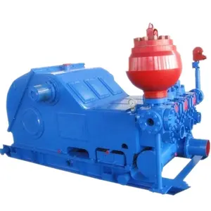
The 2,200-hp mud pump for offshore applications is a single-acting reciprocating triplex mud pump designed for high fluid flow rates, even at low operating speeds, and with a long stroke design. These features reduce the number of load reversals in critical components and increase the life of fluid end parts.
The pump’s critical components are strategically placed to make maintenance and inspection far easier and safer. The two-piece, quick-release piston rod lets you remove the piston without disturbing the liner, minimizing downtime when you’re replacing fluid parts.

A well-placed suction stabilizer can also prevent pump chatter. Pump chatter occurs when energy is exchanged between the quick opening and closing of the reciprocating pump’s valves and the hammer effect from the centrifugal pump. Pump isolation with suction stabilizers is achieved when the charge pumps are isolated from reciprocating pumps and vice versa. The results are a smooth flow of pumped media devoid of agitating energies present in the pumped fluid.

When choosing a size and type of mud pump for your drilling project, there are several factors to consider. These would include not only cost and size of pump that best fits your drilling rig, but also the diameter, depth and hole conditions you are drilling through. I know that this sounds like a lot to consider, but if you are set up the right way before the job starts, you will thank me later.
Recommended practice is to maintain a minimum of 100 to 150 feet per minute of uphole velocity for drill cuttings. Larger diameter wells for irrigation, agriculture or municipalities may violate this rule, because it may not be economically feasible to pump this much mud for the job. Uphole velocity is determined by the flow rate of the mud system, diameter of the borehole and the diameter of the drill pipe. There are many tools, including handbooks, rule of thumb, slide rule calculators and now apps on your handheld device, to calculate velocity. It is always good to remember the time it takes to get the cuttings off the bottom of the well. If you are drilling at 200 feet, then a 100-foot-per-minute velocity means that it would take two minutes to get the cuttings out of the hole. This is always a good reminder of what you are drilling through and how long ago it was that you drilled it. Ground conditions and rock formations are ever changing as you go deeper. Wouldn’t it be nice if they all remained the same?
Centrifugal-style mud pumps are very popular in our industry due to their size and weight, as well as flow rate capacity for an affordable price. There are many models and brands out there, and most of them are very good value. How does a centrifugal mud pump work? The rotation of the impeller accelerates the fluid into the volute or diffuser chamber. The added energy from the acceleration increases the velocity and pressure of the fluid. These pumps are known to be very inefficient. This means that it takes more energy to increase the flow and pressure of the fluid when compared to a piston-style pump. However, you have a significant advantage in flow rates from a centrifugal pump versus a piston pump. If you are drilling deeper wells with heavier cuttings, you will be forced at some point to use a piston-style mud pump. They have much higher efficiencies in transferring the input energy into flow and pressure, therefore resulting in much higher pressure capabilities.
Piston-style mud pumps utilize a piston or plunger that travels back and forth in a chamber known as a cylinder. These pumps are also called “positive displacement” pumps because they literally push the fluid forward. This fluid builds up pressure and forces a spring-loaded valve to open and allow the fluid to escape into the discharge piping of the pump and then down the borehole. Since the expansion process is much smaller (almost insignificant) compared to a centrifugal pump, there is much lower energy loss. Plunger-style pumps can develop upwards of 15,000 psi for well treatments and hydraulic fracturing. Centrifugal pumps, in comparison, usually operate below 300 psi. If you are comparing most drilling pumps, centrifugal pumps operate from 60 to 125 psi and piston pumps operate around 150 to 300 psi. There are many exceptions and special applications for drilling, but these numbers should cover 80 percent of all equipment operating out there.
The restriction of putting a piston-style mud pump onto drilling rigs has always been the physical size and weight to provide adequate flow and pressure to your drilling fluid. Because of this, the industry needed a new solution to this age-old issue.
As the senior design engineer for Ingersoll-Rand’s Deephole Drilling Business Unit, I had the distinct pleasure of working with him and incorporating his Centerline Mud Pump into our drilling rig platforms.
In the late ’90s — and perhaps even earlier — Ingersoll-Rand had tried several times to develop a hydraulic-driven mud pump that would last an acceptable life- and duty-cycle for a well drilling contractor. With all of our resources and design wisdom, we were unable to solve this problem. Not only did Miller provide a solution, thus saving the size and weight of a typical gear-driven mud pump, he also provided a new offering — a mono-cylinder mud pump. This double-acting piston pump provided as much mud flow and pressure as a standard 5 X 6 duplex pump with incredible size and weight savings.
The true innovation was providing the well driller a solution for their mud pump requirements that was the right size and weight to integrate into both existing and new drilling rigs. Regardless of drill rig manufacturer and hydraulic system design, Centerline has provided a mud pump integration on hundreds of customer’s drilling rigs. Both mono-cylinder and duplex-cylinder pumps can fit nicely on the deck, across the frame or even be configured for under-deck mounting. This would not be possible with conventional mud pump designs.
The second generation design for the Centerline Mud Pump is expected later this year, and I believe it will be a true game changer for this industry. It also will open up the application to many other industries that require a heavier-duty cycle for a piston pump application.

Mechanical pumps serve in a wide range of applications such as pumping water from wells, aquarium filtering, pond filtering and aeration, in the car industry for water-cooling and fuel injection, in the energy industry for pumping oil and natural gas or for operating cooling towers and other components of heating, ventilation and air conditioning systems. In the medical industry, pumps are used for biochemical processes in developing and manufacturing medicine, and as artificial replacements for body parts, in particular the artificial heart and penile prosthesis.
When a pump contains two or more pump mechanisms with fluid being directed to flow through them in series, it is called a multi-stage pump. Terms such as two-stage or double-stage may be used to specifically describe the number of stages. A pump that does not fit this description is simply a single-stage pump in contrast.
In biology, many different types of chemical and biomechanical pumps have evolved; biomimicry is sometimes used in developing new types of mechanical pumps.
Pumps can be classified by their method of displacement into positive-displacement pumps, impulse pumps, velocity pumps, gravity pumps, steam pumps and valveless pumps. There are three basic types of pumps: positive-displacement, centrifugal and axial-flow pumps. In centrifugal pumps the direction of flow of the fluid changes by ninety degrees as it flows over an impeller, while in axial flow pumps the direction of flow is unchanged.
Some positive-displacement pumps use an expanding cavity on the suction side and a decreasing cavity on the discharge side. Liquid flows into the pump as the cavity on the suction side expands and the liquid flows out of the discharge as the cavity collapses. The volume is constant through each cycle of operation.
Positive-displacement pumps, unlike centrifugal, can theoretically produce the same flow at a given speed (rpm) no matter what the discharge pressure. Thus, positive-displacement pumps are constant flow machines. However, a slight increase in internal leakage as the pressure increases prevents a truly constant flow rate.
A positive-displacement pump must not operate against a closed valve on the discharge side of the pump, because it has no shutoff head like centrifugal pumps. A positive-displacement pump operating against a closed discharge valve continues to produce flow and the pressure in the discharge line increases until the line bursts, the pump is severely damaged, or both.
A relief or safety valve on the discharge side of the positive-displacement pump is therefore necessary. The relief valve can be internal or external. The pump manufacturer normally has the option to supply internal relief or safety valves. The internal valve is usually used only as a safety precaution. An external relief valve in the discharge line, with a return line back to the suction line or supply tank provides increased safety.
Rotary-type positive displacement: internal or external gear pump, screw pump, lobe pump, shuttle block, flexible vane or sliding vane, circumferential piston, flexible impeller, helical twisted roots (e.g. the Wendelkolben pump) or liquid-ring pumps
Drawbacks: The nature of the pump requires very close clearances between the rotating pump and the outer edge, making it rotate at a slow, steady speed. If rotary pumps are operated at high speeds, the fluids cause erosion, which eventually causes enlarged clearances that liquid can pass through, which reduces efficiency.
Hollow disk pumps (also known as eccentric disc pumps or Hollow rotary disc pumps), similar to scroll compressors, these have a cylindrical rotor encased in a circular housing. As the rotor orbits and rotates to some degree, it traps fluid between the rotor and the casing, drawing the fluid through the pump. It is used for highly viscous fluids like petroleum-derived products, and it can also support high pressures of up to 290 psi.
Vibratory pumps or vibration pumps are similar to linear compressors, having the same operating principle. They work by using a spring-loaded piston with an electromagnet connected to AC current through a diode. The spring-loaded piston is the only moving part, and it is placed in the center of the electromagnet. During the positive cycle of the AC current, the diode allows energy to pass through the electromagnet, generating a magnetic field that moves the piston backwards, compressing the spring, and generating suction. During the negative cycle of the AC current, the diode blocks current flow to the electromagnet, letting the spring uncompress, moving the piston forward, and pumping the fluid and generating pressure, like a reciprocating pump. Due to its low cost, it is widely used in inexpensive espresso machines. However, vibratory pumps cannot be operated for more than one minute, as they generate large amounts of heat. Linear compressors do not have this problem, as they can be cooled by the working fluid (which is often a refrigerant).
Reciprocating pumps move the fluid using one or more oscillating pistons, plungers, or membranes (diaphragms), while valves restrict fluid motion to the desired direction. In order for suction to take place, the pump must first pull the plunger in an outward motion to decrease pressure in the chamber. Once the plunger pushes back, it will increase the chamber pressure and the inward pressure of the plunger will then open the discharge valve and release the fluid into the delivery pipe at constant flow rate and increased pressure.
Pumps in this category range from simplex, with one cylinder, to in some cases quad (four) cylinders, or more. Many reciprocating-type pumps are duplex (two) or triplex (three) cylinder. They can be either single-acting with suction during one direction of piston motion and discharge on the other, or double-acting with suction and discharge in both directions. The pumps can be powered manually, by air or steam, or by a belt driven by an engine. This type of pump was used extensively in the 19th century—in the early days of steam propulsion—as boiler feed water pumps. Now reciprocating pumps typically pump highly viscous fluids like concrete and heavy oils, and serve in special applications that demand low flow rates against high resistance. Reciprocating hand pumps were widely used to pump water from wells. Common bicycle pumps and foot pumps for inflation use reciprocating action.
These positive-displacement pumps have an expanding cavity on the suction side and a decreasing cavity on the discharge side. Liquid flows into the pumps as the cavity on the suction side expands and the liquid flows out of the discharge as the cavity collapses. The volume is constant given each cycle of operation and the pump"s volumetric efficiency can be achieved through routine maintenance and inspection of its valves.
This is the simplest form of rotary positive-displacement pumps. It consists of two meshed gears that rotate in a closely fitted casing. The tooth spaces trap fluid and force it around the outer periphery. The fluid does not travel back on the meshed part, because the teeth mesh closely in the center. Gear pumps see wide use in car engine oil pumps and in various hydraulic power packs.
A screw pump is a more complicated type of rotary pump that uses two or three screws with opposing thread — e.g., one screw turns clockwise and the other counterclockwise. The screws are mounted on parallel shafts that have gears that mesh so the shafts turn together and everything stays in place. The screws turn on the shafts and drive fluid through the pump. As with other forms of rotary pumps, the clearance between moving parts and the pump"s casing is minimal.
Widely used for pumping difficult materials, such as sewage sludge contaminated with large particles, a progressing cavity pump consists of a helical rotor, about ten times as long as its width. This can be visualized as a central core of diameter x with, typically, a curved spiral wound around of thickness half x, though in reality it is manufactured in a single casting. This shaft fits inside a heavy-duty rubber sleeve, of wall thickness also typically x. As the shaft rotates, the rotor gradually forces fluid up the rubber sleeve. Such pumps can develop very high pressure at low volumes.
Named after the Roots brothers who invented it, this lobe pump displaces the fluid trapped between two long helical rotors, each fitted into the other when perpendicular at 90°, rotating inside a triangular shaped sealing line configuration, both at the point of suction and at the point of discharge. This design produces a continuous flow with equal volume and no vortex. It can work at low pulsation rates, and offers gentle performance that some applications require.
A peristaltic pump is a type of positive-displacement pump. It contains fluid within a flexible tube fitted inside a circular pump casing (though linear peristaltic pumps have been made). A number of rollers, shoes, or wipers attached to a rotor compresses the flexible tube. As the rotor turns, the part of the tube under compression closes (or occludes), forcing the fluid through the tube. Additionally, when the tube opens to its natural state after the passing of the cam it draws (restitution) fluid into the pump. This process is called peristalsis and is used in many biological systems such as the gastrointestinal tract.
Efficiency and common problems: With only one cylinder in plunger pumps, the fluid flow varies between maximum flow when the plunger moves through the middle positions, and zero flow when the plunger is at the end positions. A lot of energy is wasted when the fluid is accelerated in the piping system. Vibration and
Triplex plunger pumps use three plungers, which reduces the pulsation of single reciprocating plunger pumps. Adding a pulsation dampener on the pump outlet can further smooth the pump ripple, or ripple graph of a pump transducer. The dynamic relationship of the high-pressure fluid and plunger generally requires high-quality plunger seals. Plunger pumps with a larger number of plungers have the benefit of increased flow, or smoother flow without a pulsation damper. The increase in moving parts and crankshaft load is one drawback.
Car washes often use these triplex-style plunger pumps (perhaps without pulsation dampers). In 1968, William Bruggeman reduced the size of the triplex pump and increased the lifespan so that car washes could use equipment with smaller footprints. Durable high-pressure seals, low-pressure seals and oil seals, hardened crankshafts, hardened connecting rods, thick ceramic plungers and heavier duty ball and roller bearings improve reliability in triplex pumps. Triplex pumps now are in a myriad of markets across the world.
Triplex pumps with shorter lifetimes are commonplace to the home user. A person who uses a home pressure washer for 10 hours a year may be satisfied with a pump that lasts 100 hours between rebuilds. Industrial-grade or continuous duty triplex pumps on the other end of the quality spectrum may run for as much as 2,080 hours a year.
The oil and gas drilling industry uses massive semi trailer-transported triplex pumps called mud pumps to pump drilling mud, which cools the drill bit and carries the cuttings back to the surface.
One modern application of positive-displacement pumps is compressed-air-powered double-diaphragm pumps. Run on compressed air, these pumps are intrinsically safe by design, although all manufacturers offer ATEX certified models to comply with industry regulation. These pumps are relatively inexpensive and can perform a wide variety of duties, from pumping water out of bunds to pumping hydrochloric acid from secure storage (dependent on how the pump is manufactured – elastomers / body construction). These double-diaphragm pumps can handle viscous fluids and abrasive materials with a gentle pumping process ideal for transporting shear-sensitive media.
Devised in China as chain pumps over 1000 years ago, these pumps can be made from very simple materials: A rope, a wheel and a pipe are sufficient to make a simple rope pump. Rope pump efficiency has been studied by grassroots organizations and the techniques for making and running them have been continuously improved.
Impulse pumps use pressure created by gas (usually air). In some impulse pumps the gas trapped in the liquid (usually water), is released and accumulated somewhere in the pump, creating a pressure that can push part of the liquid upwards.
Instead of a gas accumulation and releasing cycle, the pressure can be created by burning of hydrocarbons. Such combustion driven pumps directly transmit the impulse from a combustion event through the actuation membrane to the pump fluid. In order to allow this direct transmission, the pump needs to be almost entirely made of an elastomer (e.g. silicone rubber). Hence, the combustion causes the membrane to expand and thereby pumps the fluid out of the adjacent pumping chamber. The first combustion-driven soft pump was developed by ETH Zurich.
It takes in water at relatively low pressure and high flow-rate and outputs water at a higher hydraulic-head and lower flow-rate. The device uses the water hammer effect to develop pressure that lifts a portion of the input water that powers the pump to a point higher than where the water started.
The hydraulic ram is sometimes used in remote areas, where there is both a source of low-head hydropower, and a need for pumping water to a destination higher in elevation than the source. In this situation, the ram is often useful, since it requires no outside source of power other than the kinetic energy of flowing water.
Rotodynamic pumps (or dynamic pumps) are a type of velocity pump in which kinetic energy is added to the fluid by increasing the flow velocity. This increase in energy is converted to a gain in potential energy (pressure) when the velocity is reduced prior to or as the flow exits the pump into the discharge pipe. This conversion of kinetic energy to pressure is explained by the
A practical difference between dynamic and positive-displacement pumps is how they operate under closed valve conditions. Positive-displacement pumps physically displace fluid, so closing a valve downstream of a positive-displacement pump produces a continual pressure build up that can cause mechanical failure of pipeline or pump. Dynamic pumps differ in that they can be safely operated under closed valve conditions (for short periods of time).
Such a pump is also referred to as a centrifugal pump. The fluid enters along the axis or center, is accelerated by the impeller and exits at right angles to the shaft (radially); an example is the centrifugal fan, which is commonly used to implement a vacuum cleaner. Another type of radial-flow pump is a vortex pump. The liquid in them moves in tangential direction around the working wheel. The conversion from the mechanical energy of motor into the potential energy of flow comes by means of multiple whirls, which are excited by the impeller in the working channel of the pump. Generally, a radial-flow pump operates at higher pressures and lower flow rates than an axial- or a mixed-flow pump.
These are also referred to as All fluid pumps. The fluid is pushed outward or inward to move fluid axially. They operate at much lower pressures and higher flow rates than radial-flow (centrifugal) pumps. Axial-flow pumps cannot be run up to speed without special precaution. If at a low flow rate, the total head rise and high torque associated with this pipe would mean that the starting torque would have to become a function of acceleration for the whole mass of liquid in the pipe system. If there is a large amount of fluid in the system, accelerate the pump slowly.
Mixed-flow pumps function as a compromise between radial and axial-flow pumps. The fluid experiences both radial acceleration and lift and exits the impeller somewhere between 0 and 90 degrees from the axial direction. As a consequence mixed-flow pumps operate at higher pressures than axial-flow pumps while delivering higher discharges than radial-flow pumps. The exit angle of the flow dictates the pressure head-discharge characteristic in relation to radial and mixed-flow.
Regenerative turbine pump rotor and housing, 1⁄3 horsepower (0.25 kW). 85 millimetres (3.3 in) diameter impeller rotates counter-clockwise. Left: inlet, right: outlet. .4 millimetres (0.016 in) thick vanes on 4 millimetres (0.16 in) centers
Also known as drag, friction, peripheral, traction, turbulence, or vortex pumps, regenerative turbine pumps are class of rotodynamic pump that operates at high head pressures, typically 4–20 bars (4.1–20.4 kgf/cm2; 58–290 psi).
The pump has an impeller with a number of vanes or paddles which spins in a cavity. The suction port and pressure ports are located at the perimeter of the cavity and are isolated by a barrier called a stripper, which allows only the tip channel (fluid between the blades) to recirculate, and forces any fluid in the side channel (fluid in the cavity outside of the blades) through the pressure port. In a regenerative turbine pump, as fluid spirals repeatedly from a vane into the side channel and back to the next vane, kinetic energy is imparted to the periphery,
As regenerative turbine pumps cannot become vapor locked, they are commonly applied to volatile, hot, or cryogenic fluid transport. However, as tolerances are typically tight, they are vulnerable to solids or particles causing jamming or rapid wear. Efficiency is typically low, and pressure and power consumption typically decrease with flow. Additionally, pumping direction can be reversed by reversing direction of spin.
Steam pumps have been for a long time mainly of historical interest. They include any type of pump powered by a steam engine and also pistonless pumps such as Thomas Savery"s or the Pulsometer steam pump.
Recently there has been a resurgence of interest in low power solar steam pumps for use in smallholder irrigation in developing countries. Previously small steam engines have not been viable because of escalating inefficiencies as vapour engines decrease in size. However the use of modern engineering materials coupled with alternative engine configurations has meant that these types of system are now a cost-effective opportunity.
Valveless pumping assists in fluid transport in various biomedical and engineering systems. In a valveless pumping system, no valves (or physical occlusions) are present to regulate the flow direction. The fluid pumping efficiency of a valveless system, however, is not necessarily lower than that having valves. In fact, many fluid-dynamical systems in nature and engineering more or less rely upon valveless pumping to transport the working fluids therein. For instance, blood circulation in the cardiovascular system is maintained to some extent even when the heart"s valves fail. Meanwhile, the embryonic vertebrate heart begins pumping blood long before the development of discernible chambers and valves. Similar to blood circulation in one direction, bird respiratory systems pump air in one direction in rigid lungs, but without any physiological valve. In microfluidics, valveless impedance pumps have been fabricated, and are expected to be particularly suitable for handling sensitive biofluids. Ink jet printers operating on the piezoelectric transducer principle also use valveless pumping. The pump chamber is emptied through the printing jet due to reduced flow impedance in that direction and refilled by capillary action.
Examining pump repair records and mean time between failures (MTBF) is of great importance to responsible and conscientious pump users. In view of that fact, the preface to the 2006 Pump User"s Handbook alludes to "pump failure" statistics. For the sake of convenience, these failure statistics often are translated into MTBF (in this case, installed life before failure).
In early 2005, Gordon Buck, John Crane Inc.’s chief engineer for field operations in Baton Rouge, Louisiana, examined the repair records for a number of refinery and chemical plants to obtain meaningful reliability data for centrifugal pumps. A total of 15 operating plants having nearly 15,000 pumps were included in the survey. The smallest of these plants had about 100 pumps; several plants had over 2000. All facilities were located in the United States. In addition, considered as "new", others as "renewed" and still others as "established". Many of these plants—but not all—had an alliance arrangement with John Crane. In some cases, the alliance contract included having a John Crane Inc. technician or engineer on-site to coordinate various aspects of the program.
Not all plants are refineries, however, and different results occur elsewhere. In chemical plants, pumps have historically been "throw-away" items as chemical attack limits life. Things have improved in recent years, but the somewhat restricted space available in "old" DIN and ASME-standardized stuffing boxes places limits on the type of seal that fits. Unless the pump user upgrades the seal chamber, the pump only accommodates more compact and simple versions. Without this upgrading, lifetimes in chemical installations are generally around 50 to 60 percent of the refinery values.
Unscheduled maintenance is often one of the most significant costs of ownership, and failures of mechanical seals and bearings are among the major causes. Keep in mind the potential value of selecting pumps that cost more initially, but last much longer between repairs. The MTBF of a better pump may be one to four years longer than that of its non-upgraded counterpart. Consider that published average values of avoided pump failures range from US$2600 to US$12,000. This does not include lost opportunity costs. One pump fire occurs per 1000 failures. Having fewer pump failures means having fewer destructive pump fires.
As has been noted, a typical pump failure, based on actual year 2002 reports, costs US$5,000 on average. This includes costs for material, parts, labor and overhead. Extending a pump"s MTBF from 12 to 18 months would save US$1,667 per year — which might be greater than the cost to upgrade the centrifugal pump"s reliability.
Pumps are used throughout society for a variety of purposes. Early applications includes the use of the windmill or watermill to pump water. Today, the pump is used for irrigation, water supply, gasoline supply, air conditioning systems, refrigeration (usually called a compressor), chemical movement, sewage movement, flood control, marine services, etc.
Because of the wide variety of applications, pumps have a plethora of shapes and sizes: from very large to very small, from handling gas to handling liquid, from high pressure to low pressure, and from high volume to low volume.
Typically, a liquid pump can"t simply draw air. The feed line of the pump and the internal body surrounding the pumping mechanism must first be filled with the liquid that requires pumping: An operator must introduce liquid into the system to initiate the pumping. This is called priming the pump. Loss of prime is usually due to ingestion of air into the pump. The clearances and displacement ratios in pumps for liquids, whether thin or more viscous, usually cannot displace air due to its compressibility. This is the case with most velocity (rotodynamic) pumps — for example, centrifugal pumps. For such pumps, the position of the pump should always be lower than the suction point, if not the pump should be manually filled with liquid or a secondary pump should be used until all air is removed from the suction line and the pump casing.
Positive–displacement pumps, however, tend to have sufficiently tight sealing between the moving parts and the casing or housing of the pump that they can be described as self-priming. Such pumps can also serve as priming pumps, so-called when they are used to fulfill that need for other pumps in lieu of action taken by a human operator.
One sort of pump once common worldwide was a hand-powered water pump, or "pitcher pump". It was commonly installed over community water wells in the days before piped water supplies.
In parts of the British Isles, it was often called the parish pump. Though such community pumps are no longer common, people still used the expression parish pump to describe a place or forum where matters of local interest are discussed.
Because water from pitcher pumps is drawn directly from the soil, it is more prone to contamination. If such water is not filtered and purified, consumption of it might lead to gastrointestinal or other water-borne diseases. A notorious case is the 1854 Broad Street cholera outbreak. At the time it was not known how cholera was transmitted, but physician John Snow suspected contaminated water and had the handle of the public pump he suspected removed; the outbreak then subsided.
Modern hand-operated community pumps are considered the most sustainable low-cost option for safe water supply in resource-poor settings, often in rural areas in developing countries. A hand pump opens access to deeper groundwater that is often not polluted and also improves the safety of a well by protecting the water source from contaminated buckets. Pumps such as the Afridev pump are designed to be cheap to build and install, and easy to maintain with simple parts. However, scarcity of spare parts for these type of pumps in some regions of Africa has diminished their utility for these areas.
Multiphase pumping applications, also referred to as tri-phase, have grown due to increased oil drilling activity. In addition, the economics of multiphase production is attractive to upstream operations as it leads to simpler, smaller in-field installations, reduced equipment costs and improved production rates. In essence, the multiphase pump can accommodate all fluid stream properties with one piece of equipment, which has a smaller footprint. Often, two smaller multiphase pumps are installed in series rather than having just one massive pump.
A rotodynamic pump with one single shaft that requires two mechanical seals, this pump uses an open-type axial impeller. It is often called a Poseidon pump, and can be described as a cross between an axial compressor and a centrifugal pump.
The twin-screw pump is constructed of two inter-meshing screws that move the pumped fluid. Twin screw pumps are often used when pumping conditions contain high gas volume fractions and fluctuating inlet conditions. Four mechanical seals are required to seal the two shafts.
These pumps are basically multistage centrifugal pumps and are widely used in oil well applications as a method for artificial lift. These pumps are usually specified when the pumped fluid is mainly liquid.
A buffer tank is often installed upstream of the pump suction nozzle in case of a slug flow. The buffer tank breaks the energy of the liquid slug, smooths any fluctuations in the incoming flow and acts as a sand trap.
As the name indicates, multiphase pumps and their mechanical seals can encounter a large variation in service conditions such as changing process fluid composition, temperature variations, high and low operating pressures and exposure to abrasive/erosive media. The challenge is selecting the appropriate mechanical seal arrangement and support system to ensure maximized seal life and its overall effectiveness.
Pumps are commonly rated by horsepower, volumetric flow rate, outlet pressure in metres (or feet) of head, inlet suction in suction feet (or metres) of head.
From an initial design point of view, engineers often use a quantity termed the specific speed to identify the most suitable pump type for a particular combination of flow rate and head.
The power imparted into a fluid increases the energy of the fluid per unit volume. Thus the power relationship is between the conversion of the mechanical energy of the pump mechanism and the fluid elements within the pump. In general, this is governed by a series of simultaneous differential equations, known as the Navier–Stokes equations. However a more simple equation relating only the different energies in the fluid, known as Bernoulli"s equation can be used. Hence the power, P, required by the pump:
where Δp is the change in total pressure between the inlet and outlet (in Pa), and Q, the volume flow-rate of the fluid is given in m3/s. The total pressure may have gravitational, static pressure and kinetic energy components; i.e. energy is distributed between change in the fluid"s gravitational potential energy (going up or down hill), change in velocity, or change in static pressure. η is the pump efficiency, and may be given by the manufacturer"s information, such as in the form of a pump curve, and is typically derived from either fluid dynamics simulation (i.e. solutions to the Navier–Stokes for the particular pump geometry), or by testing. The efficiency of the pump depends upon the pump"s configuration and operating conditions (such as rotational speed, fluid density and viscosity etc.)
For a typical "pumping" configuration, the work is imparted on the fluid, and is thus positive. For the fluid imparting the work on the pump (i.e. a turbine), the work is negative. Power required to drive the pump is determined by dividing the output power by the pump efficiency. Furthermore, this definition encompasses pumps with no moving parts, such as a siphon.
Pump efficiency is defined as the ratio of the power imparted on the fluid by the pump in relation to the power supplied to drive the pump. Its value is not fixed for a given pump, efficiency is a function of the discharge and therefore also operating head. For centrifugal pumps, the efficiency tends to increase with flow rate up to a point midway through the operating range (peak efficiency or Best Efficiency Point (BEP) ) and then declines as flow rates rise further. Pump performance data such as this is usually supplied by the manufacturer before pump selection. Pump efficiencies tend to decline over time due to wear (e.g. increasing clearances as impellers reduce in size).
When a system includes a centrifugal pump, an important design issue is matching the head loss-flow characteristic with the pump so that it operates at or close to the point of its maximum efficiency.
Most large pumps have a minimum flow requirement below which the pump may be damaged by overheating, impeller wear, vibration, seal failure, drive shaft damage or poor performance.
The simplest minimum flow system is a pipe running from the pump discharge line back to the suction line. This line is fitted with an orifice plate sized to allow the pump minimum flow to pass.
A more sophisticated, but more costly, system (see diagram) comprises a flow measuring device (FE) in the pump discharge which provides a signal into a flow controller (FIC) which actuates a flow control valve (FCV) in the recycle line. If the measured flow exceeds the minimum flow then the FCV is closed. If the measured flow falls below the minimum flow the FCV opens to maintain the minimum flowrate.
As the fluids are recycled the kinetic energy of the pump increases the temperature of the fluid. For many pumps this added heat energy is dissipated through the pipework. However, for large industrial pumps, such as oil pipeline pumps, a recycle cooler is provided in the recycle line to cool the fluids to the normal suction temperature.oil refinery, oil terminal, or offshore installation.
Engineering Sciences Data Unit (2007). "Radial, mixed and axial flow pumps. Introduction" (PDF). Archived from the original (PDF) on 2014-03-08. Retrieved 2017-08-18.
Tanzania water Archived 2012-03-31 at the Wayback Machine blog – example of grassroots researcher telling about his study and work with the rope pump in Africa.
C.M. Schumacher, M. Loepfe, R. Fuhrer, R.N. Grass, and W.J. Stark, "3D printed lost-wax casted soft silicone monoblocks enable heart-inspired pumping by internal combustion," RSC Advances, Vol. 4, pp. 16039–16042, 2014.
"Radial, mixed and axial flow pumps" (PDF). Institution of Diploma Marine Engineers, Bangladesh. June 2003. Archived from the original (PDF) on 2014-03-08. Retrieved 2017-08-18.
Quail F, Scanlon T, Stickland M (2011-01-11). "Design optimisation of a regenerative pump using numerical and experimental techniques" (PDF). International Journal of Numerical Methods for Heat & Fluid Flow. 21: 95–111. doi:10.1108/09615531111095094. Retrieved 2021-07-21.
Rajmane, M. Satish; Kallurkar, S.P. (May 2015). "CFD Analysis of Domestic Centrifugal Pump for Performance Enhancement". International Research Journal of Engineering and Technology. 02 / #02. Retrieved 30 April 2021.
Wasser, Goodenberger, Jim and Bob (November 1993). "Extended Life, Zero Emissions Seal for Process Pumps". John Crane Technical Report. Routledge. TRP 28017.
Australian Pump Manufacturers" Association. Australian Pump Technical Handbook, 3rd edition. Canberra: Australian Pump Manufacturers" Association, 1987. ISBN 0-7316-7043-4.

This article is about onshore equipment for boring holes into the ground. For offshore oil rig, see Oil platform. For drilling tunnels, see Tunnel boring machine. For handheld drilling tool, see Drill.
A drilling rig is an integrated system that drills wells, such as oil or water wells, or holes for piling and other construction purposes, into the earth"s subsurface. Drilling rigs can be massive structures housing equipment used to drill water wells, oil wells, or natural gas extraction wells, or they can be small enough to be moved manually by one person and such are called augers. Drilling rigs can sample subsurface mineral deposits, test rock, soil and groundwater physical properties, and also can be used to install sub-surface fabrications, such as underground utilities, instrumentation, tunnels or wells. Drilling rigs can be mobile equipment mounted on trucks, tracks or trailers, or more permanent land or marine-based structures (such as oil platforms, commonly called "offshore oil rigs" even if they don"t contain a drilling rig). The term "rig" therefore generally refers to the complex equipment that is used to penetrate the surface of the Earth"s crust.
Small to medium-sized drilling rigs are mobile, such as those used in mineral exploration drilling, blast-hole, water wells and environmental investigations. Larger rigs are capable of drilling through thousands of metres of the Earth"s crust, using large "mud pumps" to circulate drilling mud (slurry) through the drill bit and up the casing annulus, for cooling and removing the "cuttings" while a well is drilled. Hoists in the rig can lift hundreds of tons of pipe. Other equipment can force acid or sand into reservoirs to facilitate extraction of the oil or natural gas; and in remote locations there can be permanent living accommodation and catering for crews (which may be more than a hundred). Marine rigs may operate thousands of miles distant from the supply base with infrequent crew rotation or cycle.
Antique drilling rig now on display at Western History Museum in Lingle, Wyoming. It was used to drill many water wells in that area—many of those wells are still in use.
Until internal combustion engines were developed in the late 19th century, the main method for drilling rock was muscle power of man or animal. The technique of oil drilling through percussion or rotary drilling has its origins dating back to the ancient Chinese Han Dynasty in 100 BC, where percussion drilling was used to extract natural gas in the Sichuan province.Edwin Drake to drill Pennsylvania"s first oil well in 1859 using small steam engines to power the drilling process rather than by human muscle.Cable tool drilling was developed in ancient China and was used for drilling brine wells. The salt domes also held natural gas, which some wells produced and which was used for evaporation of the brine.
In the 1970s, outside of the oil and gas industry, roller bits using mud circulation were replaced by the first pneumatic reciprocating piston Reverse Circulation (RC) drills, and became essentially obsolete for most shallow drilling, and are now only used in certain situations where rocks preclude other methods. RC drilling proved much faster and more efficient, and continues to improve with better metallurgy, deriving harder, more durable bits, and compressors delivering higher air pressures at higher volumes, enabling deeper and faster penetration. Diamond drilling has remained essentially unchanged since its inception.
Oil and natural gas drilling rigs are used not only to identify geologic reservoirs, but also used to create holes that allow the extraction of oil or natural gas from those reservoirs. Primarily in onshore oil and gas fields once a well has been drilled, the drilling rig will be moved off of the well and a service rig (a smaller rig) that is purpose-built for completions will be moved on to the well to get the well on line.
Mining drilling rigs are used for two main purposes, exploration drilling which aims to identify the location and quality of a mineral, and production drilling, used in the production-cycle for mining. Drilling rigs used for rock blasting for surface mines vary in size dependent on the size of the hole desired, and is typically classified into smaller pre-split and larger production holes. Underground mining (hard rock) uses a variety of drill rigs dependent on the desired purpose, such as production, bolting, cabling, and tunnelling.
In early oil exploration, drilling rigs were semi-permanent in nature and the derricks were often built on site and left in place after the completion of the well. In more recent times drilling rigs are expensive custom-built machines that can be moved from well to well. Some light duty drilling rigs are like a mobile crane and are more usually used to drill water wells. Larger land rigs must be broken apart into sections and loads to move to a new place, a process which can often take weeks.
Small mobile drilling rigs are also used to drill or bore piles. Rigs can range from 100 short tons (91,000 kg) continuous flight auger (CFA) rigs to small air powered rigs used to drill holes in quarries, etc. These rigs use the same technology and equipment as the oil drilling rigs, just on a smaller scale.
The drilling mechanisms outlined below differ mechanically in terms of the machinery used, but also in terms of the method by which drill cuttings are removed from the cutting face of the drill and returned to surface.
An automated drill rig (ADR) is an automated full-sized walking land-based drill rig that drills long lateral sections in horizontal wells for the oil and gas industry.Athabasca oil sands. According to the "Oil Patch Daily News", "Each rig will generate 50,000 man-hours of work during the construction phase and upon completion, each operating rig will directly and indirectly employ more than 100 workers." Compared to conventional drilling rigs", Ensign, an international oilfield services contractor based in Calgary, Alberta, that makes ADRs claims that they are "safer to operate, have "enhanced controls intelligence," "reduced environmental footprint, quick mobility and advanced communications between field and office."steam assisted gravity drainage (SAGD) applications was mobilized by Deer Creek Energy Limited, a Calgary-based oilsands company.
Baars, D.L.; Watney, W.L.; Steeples, D.W.; Brostuen, E.A (1989). Petroleum; a primer for Kansas (Educational Series, no. 7 ed.). Kansas Geological Survey. p. 40. Archived from the original on 8 November 2020. Retrieved 18 April 2011. After the cementing of the casing has been completed, the drilling rig, equipment, and materials are removed from the drill site. A smaller rig, known as a workover rig or completion rig, is moved over the well bore. The smaller rig is used for the remaining completion operations.

Owners depend on the 3100GT drilling truck to perform jobs efficiently, paramount for successful geotechnical sampling. Profits lie not only in getting footage done quickly and easily, but above all, safely. Quality construction and numerous features and options on the drilling truck provide versatility to outperform the competition.
EFFECTIVE: versatility to complete an array of sampling techniques – in unconsolidated and consolidated formations - with a single machine without compromise. Separate hydraulic circuit dedicated to mud pump provides stable mud flow.
EFFICIENT: fuel-efficient transport averages 15 mpg and minimizes maintenance expenses supporting only one engine while providing power to travel at highway speeds. Ample storage keeps tools right where you need them near the control panel or on the breakout. And because the drilling truck is under class A/B CDL, save on insurance and streamline hiring of new drillers.
With drill rig service shops in Pennsylvania, Florida, and Kansas, you’ll have service support nearby for your routine maintenance or more in-depth drill rig remounting and refurbishment work. Our service technicians are backed by our team of engineers to ensure solutions not bandaids to issues. And our production processes mean your drilling truck is constructed consistently and tested thoroughly to ensure easier service support.
Six functions along the 28-inch centerline head side shift simplify traditional geotechnical applications — augering, mud rotary, SPT, Shelby tubes, hard rock cores, CPT – and even direct push. Features GH63 percussion hammer 4-speed rotary head with 4,000 ft-lb, DH104 hands-free automatic drop hammer, CPT push/pull assembly, and a rod grip pull system. Head shifting speeds up drilling and minimizes the time driller spends in danger zone.
Drill mast features extend, swing, mast dump, oscillation, and fold. Mast dump provides 36.5 inches of vertical travel to allow room for a mud pan. Outriggers let you quickly set up above the mud pan as well.
Hands-free rotary and head feed controls on the 3100GT reduce strain on driller when completing applications like mud rotary. CPT feed rate and hydraulic limit functions are standard.
Pump options for the 3100GT include the Moyno® 3L6 or Moyno® 3L8 pumps. The pump is controlled at the control panel with an on/off switch and the flow can be adjusted with a flow dial.

The need for mud pumps has increased along with the growing demand for minerals, oil, and gas. The market for mud pumps is anticipated to grow throughout the forecast period due to increased offshore mining activities and the globally expanding population. With the advantages it offers, the mud pumps market is expected to grow quickly. The market would be further boosted by rising demand for directional and horizontal drilling as well as the mud pump"s capacity to handle high-pressure drilling activities.
Due to technological advancements, mud pumps operate more efficiently and without producing harmful carbon emissions. Electric mud pumps are in higher demand, which may create new prospects for market expansion. The performance of mud pumps is influenced by the pump design along with a variety of other elements like pipelines, panel boards, and electricity. For maximum efficiency, manufacturers are therefore concentrating on improvements to the overall pumping system, which is aiding the mud pumps market.
Mud pumps are attracting attention as an innovative component of offshore drilling equipment as every hour, mud pumps help reach deeper levels, saving the rig operator time and money. In on-shore drilling, for instance, 7500-psi mud pump systems are becoming common.
Mud pumps are a particular kind of piston/plunger-driven pump that can use drilling fluids while under high pressure. Mud pumps are typically used in conjunction with other pumps and are a crucial component of heavy drilling techniques. These pumps assist in returning the drilling fluid to the surface after it has passed past the drill bit.
Triplex pumps are likely to hold a significant mud pumps market share since triplex pumps are lighter and more efficient than duplex pumps. Triplex mud pumps are widely used to circulate high-pressure drilling fluid for deep oil well drilling applications. They are more advantageous for use, especially in onshore and offshore oil well drilling applications, due to these applications.
The electrically powered mud pump market is expanding quickly due to its environmental advantages over fuel engine pumps. The mud pumps market value is anticipated to increase as a result of the increased exploration operations being carried out in all regions of the world to satisfy the growing demand for energy and minerals. In nations including the United States, Canada, China, and Argentina, shale gas exploration has expanded, which will raise the demand for oil rigs and consequently mud pumps.
The use of oil rigs, equipment, and mud pumps is being accelerated by operators in nations like the United States who are also relocating to isolated areas in Alaska. Old pumps are now being replaced by many governments, and oil and gas production businesses in Europe and the United States have noticed a continuous growth in this trend, thus aiding the market growth of mud pumps.


 8613371530291