
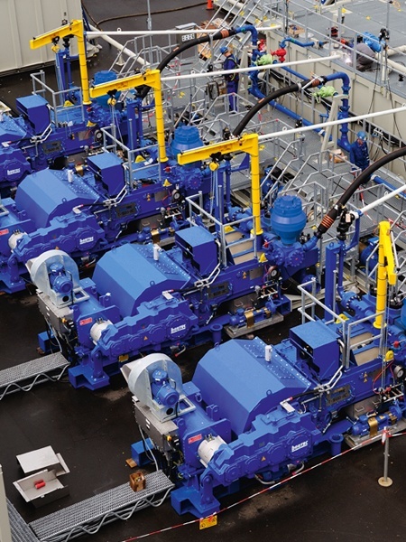
drilling rig mud pump knocking sound factory
My first days as an MWD field tech I heard horror stories surrounding what is commonly referred to as “pump noise”. I quickly identified the importance of learning to properly identify this “noise”. From the way it was explained to me, this skill might prevent the company you work from losing a job with an exploration company, satisfy your supervisor or even allow you to become regarded as hero within your organization if you’ve proven yourself handy at this skill.
“Pump noise” is a reference to an instability in surface pressure created by the mud pumps on a modern drilling rig, often conflated with any pressure fluctuation at a similar frequency to pulses generated by a mud pulser, but caused by a source external to the mud pulser. This change in pressure is what stands in the way of the decoder properly understanding what the MWD tool is trying to communicate. For the better part of the first year of learning my role I wrongly assumed that all “noise” would be something audible to the human ear, but this is rarely the case.
In an ideal drilling environment surface pressure will remain steady and all pressure increases, and decreases will be gradual. This way, when the pulser valve closes(pulses), it’s easily detectable on surface by computers. Unfortunately drilling environments are rarely perfect and there are many things that can emulate a pulse thus causing poor or inaccurate data delivery to surface. The unfortunate circumstance of this means drilling operations must come to halt until data can once again be decoded on surface. This pause in the drilling process is commonly referred to at NPT or non-productive time. For those of you unfamiliar these concepts, I’ll explain some of the basics.
A mud pulser is a valve that briefly inhibits flow of drilling fluid traveling through the drill string, creating a sharp rise and fall of pressure seen on surface, also known as a “pulse”.
Depending on if the drilling fluid is being circulated in closed or open loop, it will be drawn from a tank or a plastic lined reservoir by a series(or one) mud pumps and channeled into the stand pipe, which runs up the derrick to the Kelly-hose, through the saver sub and down the drill-pipe(drill-string). Through the filter screen past an agitator or exciter, around the MWD tool, through a mud motor and out of the nozzles in the bit. At this point the fluid begins it’s journey back to the drilling rig through the annulus, past the BOP then out of the flow line and either over the shale shakers and/or back in the fluid reservoir.
Developing a firm grasp on these fundamentals were instrumental in my success as a field technician and an effective troubleshooter. As you can tell, there are a lot of components involved in this conduit which a mud pulser telemeters through. The way in which many of these components interact with the drilling fluid can suddenly change in ways that slightly create sharp changes in pressure, often referred to as “noise”. This “noise” creates difficulty for the decoder by suddenly reducing or increasing pressure in a manner that the decoder interprets a pulse. To isolate these issues, you must first acknowledge potential of their existence. I will give few examples of some of these instances below:
Suction screens on intake hoses will occasionally be too large, fail or become unfastened thus allowing large debris in the mud system. Depending on the size of debris and a little bit of luck it can end up in an area that will inhibit flow, circumstantially resulting in a sudden fluctuation of pressure.
Any solid form of drilling fluid additive, if improperly or inconsistently mixed, can restrict the flow path of the fluid resulting in pressure increase. Most notably this can happen at the pulser valve itself, but it is not the only possible outcome. Several other parts of this system can be affected as well. LCM or loss of circulation material is by far the most common additive, but the least overlooked. It’s important for an MWD technician to be aware of what’s being added into the drilling fluid regardless if LCM isn’t present. Through the years I have seen serval other improperly mixed additives cause a litany of pressure related issues.
This specifically is a term used to refer to the mud motor stator rubber deterioration, tearing into small pieces and passing through the nozzles of the bit. Brief spikes in pressure as chunks of rubber pass through one or more nozzles of the bit can often be wrongly interpreted as pulses.
Sometimes when mud is displaced or a pump suction isn’t completely submerged, tiny air bubbles are introduced into the drilling fluid. Being that air compresses and fluid does not, pulses can be significantly diminished and sometimes non-existent.
As many of you know the downhole mud motor is what enables most drilling rigs to steer a well to a targeted location. The motor generates bit RPM by converting fluid velocity to rotor/bit RPM, otherwise known as hydraulic horsepower. Anything downhole that interacts with the bit will inevitably affect surface pressure. One of the most common is bit weight. As bit weight is increased, so does surface pressure. It’s important to note that consistent weight tends to be helpful to the decoder by increasing the amplitude of pulses, but inconsistent bit weight, depending on frequency of change, can negatively affect decoding. Bit bounce, bit bite and inconsistent weight transfer can all cause pressure oscillation resulting in poor decoding. Improper bit speed or bit type relative to a given formation are other examples of possible culprits as well.
Over time mud pump components wear to the point failure. Pump pistons(swabs), liners, valves and valve seats are all necessary components for generating stable pressure. These are the moving parts on the fluid side of the pump and the most frequent point of failure. Another possible culprit but less common is an inadequately charged pulsation dampener. Deteriorating rubber hoses anywhere in the fluid path, from the mud pump to the saver sub, such as a kelly-hose, can cause an occasional pressure oscillation.
If I could change one thing about today’s directional drilling industry, it would be eliminating the term “pump noise”. The misleading term alone has caused confusion for countless people working on a drilling rig. On the other hand, I’m happy to have learned these lessons the hard way because they seem engrained into my memory. As technology improves, so does the opportunities for MWD technology companies to provide useful solutions. Solutions to aid MWD service providers to properly isolate or overcome the challenges that lead to decoding issues. As an industry we have come a lot further from when I had started, but there is much left to be desired. I’m happy I can use my experiences by contributing to an organization capable of acknowledging and overcoming these obstacles through the development of new technology.
I recently visited a well-known copper mine that had contacted us after hearing some irregular noises coming from their brand new pump. The noises were obviously causing them some panic, especially with it being from a new pump. They were convinced the sounds were being caused by either a bearing issue or the impeller rubbing.
After arriving on site, we started up the pump again and that noise they had mentioned over the phone was very much alive and present, but after years of experience listening to equipment I was not convinced it was the impeller or the bearings. There was no knocking or rubbing sounds like you would hear if it were the impeller. The bearings weren’t making any unusual noises such as grinding and their temperatures were normal. If the bearing temperatures are in the 160-180 degrees Fahrenheit range, then it’s safe to say you likely don’t have a bearing issue.
I asked them to remove the belt guard and check the tension on the belts. (This is where I will note that the factory typically does not ship pumps with belts and sheaves installed, as was the case here. The customer was sent these items as part of the shipment and they were installed on site by the customer).
When we checked the tension of the belts on site, sure enough the belts were slack. I asked them to tighten the belts, put the belt guard back on and try again. The noise was gone and the pump has been running great ever since.
This story is a great reminder to us all. First of all, it is good policy to check the tension on your belts every 3-4 months. New belts will stretch as they run and will need to be adjusted frequently to ensure proper tension. Secondly, as was the case with this customer, noises can be caused by many factors on a pump. Sometimes if you are unsure and before spending lots of money renting equipment like cranes to lift a pump out of a sump or putting yourself through a costly downtime situation while you chase a mysterious problem, start from the top (at the belts). It could save you a ton of cash. The tool I use to measure the tension of belts is called a Gates Belt Tension gauge/tool. It comes with a paper that has a formula and chart as to how much tension should be on the belt.
If you have a pump problem you’d like me to weigh in on or any questions, I’d love to hear them. If you want me to come and check out a pump issue you’re having on site – feel free to call or email.
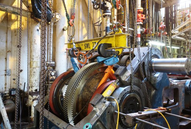
Many hours and even days can be wasted because of lack of preventive maintenance. Repairing a rig.With today"s technology, the instruction and parts manual included with new equipment is one of the most important pieces included. Some manufacturers include two complete sets of manuals, one for the office and one for the rig. Take care of them as if they were gold.
Don"t tell the parts man, “You know, the so and so on my rig.” Today"s manufacturers build so many models that they too must refer to the manuals. Most manufacturers keep a copy of the parts manual for your specific equipment on file and will be able to refer to it immediately.
I was a field representative and troubleshooter for several different drilling manufacturers over the years. Once, I was sent to check out a mud pump problem on a newly built drill. Through the assistance of the driller, machine shop, the manufacturer and myself, we found the manufacturer had missed a step in the machining process, causing the pump valves and seats to cut out prematurely. We were authorized by the manufacturer to have this process performed locally and the invoice sent to them. Later, we found this manufacturer had had many of these pumps missing this same machining process. Eventually, all were rectified.
Another time, we had a new drilling machine engine that was gaining lubricating oil. In further communication with the engine manufacturer, we were advised there was a defective part causing the problem. It was injecting too much diesel, getting by the rings and getting into the oil pan, thinning the oil. Shortly, this would cause the new engine to be damaged or destroyed. The engine field representative/mechanic was sent to the site to take care of the under-warranty repair. This observation by my son, Chris “Piglet” Cutter, CWD/PI, not only saved the engine, it also saved the driller a lot of down time, and the manufacturer, many dollars.
We found a new drilling machine with the winch cable rubbing the mast and that wouldn"t hold a load. We found the cable had been wound on the drum backwards. Reversing the cable winding eliminated the cable rubbing the mast and made the automatic brake hold the load. We switched the hydraulic lines on the up/down lever so that they worked and read correctly.
Back in 1966, I found that when using the pulldown on a new drill, it actually pulled up instead of down. The pulldown chains were crossed at the factory. I advised the purchaser that I knew this manufacturer tested each drill for a minimum of 48 hours on a test rack before sending it out; there was something not right here. Upon further investigation, we found that the rig had been run on the test rack and checked OK. However, they were short of pulldown chain later and removed the chains from this drill and installed them on a more urgent drill sale. When the new chain arrived, it was installed on our drill and not run on the test rack again.
I"ve seen piston pumps that were knocking and not pumping well. We pulled the heads and found the pump pistons loose on pump rods. We changed the pistons and the piston rods and everything worked fine. We"ve found knocking in piston pumps that was caused from simple things such as leaking suction, collapsed suction hose (inner liner) or from restricted suction (oil can stuck in the suction hose).
A client once complained that his new drill on the manufacturer"s test rack had a noise in the piston mud pump. The test rack people tried to tell this experienced driller it only was a leak in the suction line causing the noise. The driller requested the test rack remove the gear end cover to check the gear end. Reluctantly, they did and found the gear oil filled with brass particles. Needless to say, after some serious conversation and demands from the buyer, they replaced the whole pump.
Occasionally, a new drilling machine will have a vibration that the manufacturer missed. A client complained to the test rack that his new drill had a vibration. Further checking revealed that an air clutch had been improperly assembled, causing it to be out of balance. Had the buyer not noticed the problem at the factory, it eventually would have cost the buyer a lot of money and downtime, as it probably would have been out of warranty.
In 1967, while delivering a new drilling rig from Enid, Okla., to Atlanta and eventually operating this drill for the Georgia Institute of Technology, I found the new Ford F-850 tandem-axle truck only had front-wheel brakes. Going slow, it stopped great but with some speed, the front wheels only slid when trying to stop. I lifted the rig off the wheels with the leveling jacks, ran it up to about 20 miles per hour, and then hit the brakes - and the back wheels just kept spinning. There was no air getting to the rear wheels.

Excessive or erratic hydraulic pump noise is a symptom of malfunction that could cause damage or accelerated wear if not addressed quickly and correctly. While it’s never nice to hear strange noises emitted from your pump, different forms of noise, which are related to different faults can provide valuable clues that can help you to diagnose your problem and get it fixed before it turns into something major.
So it pays to know what different pump noises mean and with practice you can quickly distinguish between the normal operating sounds and signs that something is wrong. In this article, we’ll talk about what causes some of these sounds, so you can identify them.
A constant hissing sound is indicative of a relief valve that is set too low or is stuck open and is continually releasing pressure. An erratic whistling sound is a symptom that a relief valve is set incorrectly or is damaged. It is common for pump settings to be changed carelessly or inadvertently - sometimes to overcome other issues with the hydraulic system - sometimes due to a lack of understanding of the correct operating conditions, so include this in your regular checks. In addition to noise problems, relief valve damage can be accompanied by slamming of actuators, stalls and excessive heat generation.
Noise issues are just one symptom that gives you a clue when things go wrong with your hydraulic pump. There are several other issues to know and understand, which could help you to identify pump problems quicker. Which means you can sort them out sooner - potentially saving big money down the road. These include heat problems, pressure problems and flow problems.

Cavitation is an undesirable condition that reduces pump efficiency and leads to excessive wear and damage to pump components. Factors that can contribute to cavitation, such as fluid velocity and pressure, can sometimes be attributed to an inadequate mud system design and/or the diminishing performance of the mud pump’s feed system.
When a mud pump has entered full cavitation, rig crews and field service technicians will see the equipment shaking and hear the pump “knocking,” which typically sounds like marbles and stones being thrown around inside the equipment. However, the process of cavitation starts long before audible signs reveal themselves – hence the name “the silent killer.”
Mild cavitation begins to occur when the mud pump is starved for fluid. While the pump itself may not be making noise, damage is still being done to the internal components of the fluid end. In the early stages, cavitation can damage a pump’s module, piston and valve assembly.
The imperceptible but intense shock waves generated by cavitation travel directly from the fluid end to the pump’s power end, causing premature vibrational damage to the crosshead slides. The vibrations are then passed onto the shaft, bull gear and into the main bearings.
If not corrected, the vibrations caused by cavitation will work their way directly to critical power end components, which will result in the premature failure of the mud pump. A busted mud pump means expensive downtime and repair costs.
Washouts are one of the leading causes of module failure and take place when the high-pressure fluid cuts through the module’s surface and damages a sealing surface. These unexpected failures are expensive and can lead to a minimum of eight hours of rig downtime for module replacement.
To stop cavitation before it starts, install and tune high-speed pressure sensors on the mud suction line set to sound an alarm if the pressure falls below 30 psi.
Although the pump may not be knocking loudly when cavitation first presents, regular inspections by a properly trained field technician may be able to detect moderate vibrations and slight knocking sounds.
Gardner Denver offers Pump University, a mobile classroom that travels to facilities and/or drilling rigs and trains rig crews on best practices for pumping equipment maintenance.
Severe cavitation will drastically decrease module life and will eventually lead to catastrophic pump failure. Along with downtime and repair costs, the failure of the drilling pump can also cause damage to the suction and discharge piping.
When a mud pump has entered full cavitation, rig crews and field service technicians will see the equipment shaking and hear the pump ‘knocking’… However, the process of cavitation starts long before audible signs reveal themselves – hence the name ‘the silent killer.’In 2017, a leading North American drilling contractor was encountering chronic mud system issues on multiple rigs. The contractor engaged in more than 25 premature module washes in one year and suffered a major power-end failure.
Gardner Denver’s engineering team spent time on the contractor’s rigs, observing the pumps during operation and surveying the mud system’s design and configuration.
The engineering team discovered that the suction systems were undersized, feed lines were too small and there was no dampening on the suction side of the pump.
Following the implementation of these recommendations, the contractor saw significant performance improvements from the drilling pumps. Consumables life was extended significantly, and module washes were reduced by nearly 85%.
Although pump age does not affect its susceptibility to cavitation, the age of the rig can. An older rig’s mud systems may not be equipped for the way pumps are run today – at maximum horsepower.
It may be impractical to flush system piping during drilling operations. However, strainer screens should be checked daily to remove any debris or other flow restrictions.
Measurement While Drilling tool is used to get realtime downhole data while drilling and used to make correct decision as soon as possible. The key to get realtime data is to decode the transmitted MWD signal on surface. Unable to decode transmitted signal may lead to loss of money, or even safety issue.
This article will focus on understanding of MWD signal decoding which is transmitted via mud pulse telemetry since this method of transmission is the most widely used commercially in the world.
As a basic idea, one must know that transmitted MWD signal is a wave that travels through a medium. In this case, the medium is mud column inside the drill string to mud pumps. Decoding is about detecting the travelling wave and convert it into data stream to be presented as numerical or graphical display.
The signal is produced by downhole transmitter in the form of positive pulse or negative pulse. It travels up hole through mud channel and received on the surface by pressure sensor. From this sensor, electrical signal is passed to surface computer via electrical cable.
On the way the signal leaves the transmitter, it experiences lots of disturbances that make the original signal distorted to various level, from minor distortion to severe distortion which makes decoding impossible. These disturbances are called noises.
Noise sources are bit, drill string vibration, bottom hole assemblies, signal reflection and mud pumps. Other than the noises, the signal is also dampened by the mud which make the signal becomes weak at the time it reaches the pressure sensor. Depth also weaken the signal strength, the deeper the depth, the weaker the signal detected.
Rock bit may create tri-lobe pattern. This pattern is created by the cones of the bit on the bottom of the hole. While drilling, the bit’s cones ride along this tri-lobe pattern and makes the bit bounce or known as axial vibration. As the bit bounces, back pressure is produced at the bit nozzles and transmitted to surface. The frequency of the noise created by bit bounce correlates with bit RPM. The formula to calculate its frequency is 3*(bit RPM)/60. When the bit bounce frequency match with MWD signal frequency, decoding is affected.
BHA components that have moving mechanical parts such as positive mud motor and agitator create noise at certain frequency. The frequency produced by these assemblies depends on the flow rate and the lobe configuration. The higher the flow rate and the higher the lobe configuration creates higher noise frequency.
Thruster, normally made up above MWD tool, tends to dampen the MWD signal significantly. It has a nozzle to use mud hydraulic power to push its spline mandrel – and then push the BHA components beneath it including the bit – against bottom of the hole. When the MWD signal is passing through the nozzle, the signal loses some of its energy. Weaker signal will then be detected on surface.
When the wave hits a solid surface like a pipe bend or a closed valve the wave will be reflected backward against the direction of original MWD signal as described in figure 2 below.
The pressure sensor on the pipe manifold detects 2 identical signals, one from the original MWD transmitter and another one comes from signal reflection, which are separated in some milliseconds. The result seen by the surface computer is the sum of those two signals. Depending on the individual signal width and the timing when the reflected signal arrives at the pressure sensor, surface computer may see a wider signal width or two identical signals adjacent to each other.
The common sources of signal reflection are pipe bending, change in pipe inner diameter or closed valve. These are easily found in pipe manifold on the rig floor. To avoid the signal reflection problem, the pressure sensor must be mounted in a free reflection source area, for example close to mud pumps. The most effective way to solve this problem is using dual pressure sensors method.
Mud pump is positive displacement pump. It uses pistons in triplex or duplex configuration. As the piston pushes the mud out of pump, pressure spikes created. When the piston retracts, the pressure back to idle. The back and forth action of pistons produce pressure fluctuation at the pump outlet.
Pressure fluctuation is dampened by a dampener which is located at the pump outlet. It is a big rounded metal filled with nitrogen gas and separated by a membrane from the mud output. When the piston pushes the mud the nitrogen gas in the dampener will be compressed storing the pressure energy; and when the piston retracts the compressed nitrogen gas in the dampener release the stored energy. So that the output pressure will be stable – no pressure fluctuation.
The dampener needs to be charged by adding nitrogen gas to certain pressure. If the nitrogen pressure is not at the right pressure, either too high or too low, the pump output pressure fluctuation will not be stabilized. This pressure fluctuation may match the MWD frequency signal and hence it disturbs decoding, it is called pump noise.
When the pump noise occurs, one may simply change the flow rate (stroke rate) so that the pump noise frequency fall outside the MWD frequency band – and then apply band pass frequency to the decoder.
The formula to calculate pump noise frequency is 3*(pump stroke rate)/60 for triplex pump and 2*(pump stroke rate)/60 for duplex pump. The rule of thumb to set up dampener pressure charge is a third (1/3) of the working standpipe pressure.
Sometime the MWD signal is not detected at all when making surface test although the MWD tool is working perfectly. This happen whenever the stand pipe pressure is the same with the pump dampener pressure. Reducing or increasing test flow rate to reduce or increase stand pipe pressure helps to overcome the problem.
When the MWD signal wave travels through mud as the transmission medium, the wave loses its energy. In other words, the wave is giving some energy to the mud.
The mud properties that are affecting MWD signal transmission is viscosity and weight. The increasing mud weight means there is more solid material or heavier material in the mud. Sometimes the mud weight increment is directly affecting mud viscosity to become higher. The MWD signal wave interacts with those materials and thus its energy is reduced on its way to surface. The more viscous the mud and the heavier the mud, the weaker the signal detected on surface.
Aerated mud often used in underbalance drilling to keep mud influx into the formation as low as possible. The gas injected into the mud acts as signal dampener as gas bubble is compressible. MWD signal suffers severely in this type of mud.
Proper planning before setting the MWD pulser gap, flow rate and pump dampener pressure based on mud properties information is the key to overcome weak signal.
The further the signal travels, the weaker the signal detected on the surface. The amount of detected signal weakness ratio compare to the original signal strength when it is created at the pulser depends on many factors, for example, mud properties, BHA component, temperature and surface equipment settings.
Rigging up sensor cables especially on the offshore rig is challenging since the cables must not create safety hazard to other people and equipment’s. Most of the time the cables must be run alongside rig’s high voltage electrical cables. The high voltage may induce sensor cables which creates continuous or temporal spiky signal in the surface decoder.

The pump is designed to circulate mud or drilling fluid under great pressure down the drill hole and back up. The pump is a reciprocating model that features five pistons, hence the name quintuplex mud pump. The right degree of pressure and precision is crucial for efficient well operations. At Shale Pumps, we understand the value of a well designed and manufactured quintuplex pump, lending great focus on robust build and superior engineering quality.
Despite the fact that all mud pumps have pulsation dampeners, noise levels are likely to be high and require modifications to keep noise pollution levels low. This is important, considering the long-running hours of equipment and the need to protect personnel from constant and high noise levels. With a quintuplex mud pump, the pulsation noise and the mud telemetry noise come down by as much as half, making operations less noisy.
At Shale Pumps the designs of quintuplex mud pumps incorporate smaller footprints making the pumps more compact. Despite the smaller size of the pumps, the quintuplex pumps are rated for continuous duty with greater efficiency. The pressurized lubrication system with lubrication pumps mounted on the outside makes it easy for maintenance, reducing downtime of the equipment.
The build quality of the quintuplex mud pumps, much like the other equipment we manufacture and assemble at Shale pumps are superior, as a result of the materials, the design, and the processes employed in the assembly line. For detailed information about the service call at 713.248.3999 or mail at sales@shalepumps.com.

Researchers have shown that mud pulse telemetry technologies have gained exploration and drilling application advantages by providing cost-effective real-time data transmission in closed-loop drilling operations. Given the inherited mud pulse operation difficulties, there have been numerous communication channel efforts to improve data rate speed and transmission distance in LWD operations. As discussed in “MPT systems signal impairments”, mud pulse signal pulse transmissions are subjected to mud pump noise signals, signal attenuation and dispersion, downhole random (electrical) noises, signal echoes and reflections, drillstring rock formation and gas effects, that demand complex surface signal detection and extraction processes. A number of enhanced signal processing techniques and methods to signal coding and decoding, data compression, noise cancellation and channel equalization have led to improved MPT performance in tests and field applications. This section discusses signal-processing techniques to minimize or eliminate signal impairments on mud pulse telemetry system.
At early stages of mud pulse telemetry applications, matched filter demonstrated the ability to detect mud pulse signals in the presence of simulated or real noise. Matched filter method eliminated the mud noise effects by calculating the self-correlation coefficients of received signal mixed with noise (Marsh et al. 1988). Sharp cutoff low-pass filter was proposed to remove mud pump high frequencies and improve surface signal detection. However, matched filter method was appropriate only for limited single frequency signal modulated by frequency-shift keying (FSK) with low transmission efficiency and could not work for frequency band signals modulated by phase shift keying (PSK) (Shen et al. 2013a).
Wavelet transform method was developed and widely adopted and used in signal processing to overcome limitation of Fourier transform in time domain (Bultheel 2003). Although Fourier and its revised fast Fourier transforms are powerful mathematical tool, they are not very good at detecting rapid changes in signals such as seismic data and well test data in petroleum industry containing many structure of different scales (Multi-scale structures) (Guan et al. 2004). Fourier coefficients do not provide direct information about the signal local behavior (localization); but the average strength of that frequency in the full signal as the sine or cosine function keeps undulating to infinity. Wavelet transform analyzes the signal frequency components and time segment, and fine tune sampling of localized characters of time or frequency domain. Principles of wavelet transform and de-noising technique show that signal can be divided into space and scale (time and frequency) without losing any useful information of the original signal, hence ensuring the extraction of useful information from the noised signal (Li et al. 2007). Different wavelet base parameters constructed, such as haar, db, coif, sym, bior, rbio and dmey, are suitable for different signal processing requirements. The small the scale parameter is, the higher the resolving power in frequency, suitable for processing high frequency signals; conversely, the larger the scale is the higher resolving power suitable for low frequency signal.
In processing noise-contaminated mud pulse signals, longer vanishing moments are used, but takes longer time for wavelet transform. The main wavelet transform method challenges include effective selection of wavelet base, scale parameters and vanishing moment; the key determinants of signal correlation coefficients used to evaluate similarities between original and processed signals. Chen et al. (2010) researched on wavelet transform and de-noising technique to obtain mud pulse signals waveform shaping and signal extraction based on the pulse-code information processing to restore pulse signal and improve SNR. Simulated discrete wavelet transform showed effective de-noise technique, downhole signal was recovered and decoded with low error rate. Namuq et al. (2013) studied mud pulse signal detection and characterization technique of non-stationary continuous pressure pulses generated by the mud siren based on the continuous Morlet wavelet transformation. In this method, generated non-stationary sinusoidal pressure pulses with varying amplitudes and frequencies used ASK and FSK modulation schemes. Simulated wavelet technique showed appropriate results for dynamic signal characteristics analysis.
As discussed in “MPT mud pump noises”, the often overlap of the mud pulses frequency spectra with the mud pump noise frequency components adds complexity to mud pulse signal detection and extraction. Real-time monitoring requirement and the non-stationary frequency characteristics made the utilization of traditional noise filtering techniques very difficult (Brandon et al. 1999). The MPT operations practical problem contains spurious frequency peaks or outliers that the standard filter design cannot effectively eliminate without the possibility of destroying some data. Therefore, to separate noise components from signal components, new filtering algorithms are compulsory.
Early development Brandon et al. (1999) proposed adaptive compensation method that use non-linear digital gain and signal averaging in the reference channel to eliminate the noise components in the primary channel. In this method, synthesized mud pulse signal and mud pump noise were generated and tested to examine the real-time digital adaptive compensation applicability. However, the method was not successfully applied due to complex noise signals where the power and the phases of the pump noises are not the same.
Jianhui et al. (2007) researched the use of two-step filtering algorithms to eliminate mud pulse signal direct current (DC) noise components and attenuate the high frequency noises. In the study, the low-pass finite impulse response (FIR) filter design was used as the DC estimator to get a zero mean signal from the received pressure waveforms while the band-pass filter was used to eliminate out-of-band mud pump frequency components. This method used center-of-gravity technique to obtain mud pulse positions of downhole signal modulated by pulse positioning modulation (PPM) scheme. Later Zhao et al. (2009) used the average filtering algorithm to decay DC noise components and a windowed limited impulse response (FIR) algorithm deployed to filter high frequency noise. Yuan and Gong (2011) studied the use of directional difference filter and band-pass filter methods to remove noise on the continuous mud pulse differential binary phase shift keying (DBPSK) modulated downhole signal. In this technique, the directional difference filter was used to eliminate mud pump and reflection noise signals in time domain while band-pass filter isolated out-of-band noise frequencies in frequency domain.
Other researchers implemented adaptive FIR digital filter using least mean square (LMS) evaluation criterion to realize the filter performances to eliminate random noise frequencies and reconstruct mud pulse signals. This technique was adopted to reduce mud pump noise and improve surface received telemetry signal detection and reliability. However, the quality of reconstructed signal depends on the signal distortion factor, which relates to the filter step-size factor. Reasonably, chosen filter step-size factor reduces the signal distortion quality. Li and Reckmann (2009) research used the reference signal fundamental frequencies and simulated mud pump harmonic frequencies passed through the LMS filter design to adaptively track pump noises. This method reduced the pump noise signals by subtracting the pump noise approximation from the received telemetry signal. Shen et al. (2013a) studied the impacts of filter step-size on signal-to-noise ratio (SNR) distortions. The study used the LMS control algorithm to adjust the adaptive filter weight coefficients on mud pulse signal modulated by differential phase shift keying (DPSK). In this technique, the same filter step-size factor numerical calculations showed that the distortion factor of reconstructed mud pressure QPSK signal is smaller than that of the mud pressure DPSK signal.
Study on electromagnetic LWD receiver’s ability to extract weak signals from large amounts of well site noise using the adaptive LMS iterative algorithm was done by (Liu 2016). Though the method is complex and not straightforward to implement, successive LMS adaptive iterations produced the LMS filter output that converges to an acceptable harmonic pump noise approximation. Researchers’ experimental and simulated results show that the modified LMS algorithm has faster convergence speed, smaller steady state and lower excess mean square error. Studies have shown that adaptive FIR LMS noise cancellation algorithm is a feasible effective technique to recover useful surface-decoded signal with reasonable information quantity and low error rate.
Different techniques which utilize two pressure sensors have been proposed to reduce or eliminate mud pump noises and recover downhole telemetry signals. During mud pressure signal generation, activated pulsar provides an uplink signal at the downhole location and the at least two sensor measurements are used to estimate the mud channel transfer function (Reckmann 2008). The telemetry signal and the first signal (pressure signal or flow rate signal) are used to activate the pulsar and provide an uplink signal at the downhole location; second signal received at the surface detectors is processed to estimate the telemetry signal; a third signal responsive to the uplink signal at a location near the downhole location is measured (Brackel 2016; Brooks 2015; Reckmann 2008, 2014). The filtering process uses the time delay between first and third signals to estimate the two signal cross-correlation (Reckmann 2014). In this method, the derived filter estimates the transfer function of the communication channel between the pressure sensor locations proximate to the mud pump noise source signals. The digital pump stroke is used to generate pump noise signal source at a sampling rate that is less than the selected receiver signal (Brackel 2016). This technique is complex as it is difficult to estimate accurately the phase difference required to give quantifiable time delay between the pump sensor and pressure sensor signals.
As mud pulse frequencies coincide with pump noise frequency in the MPT 1–20 Hz frequency operations, applications of narrow-band filter cannot effectively eliminate pump noises. Shao et al. (2017) proposed continuous mud pulse signal extraction method using dual sensor differential signal algorithm; the signal was modulated by the binary frequency-shift keying (BFSK). Based on opposite propagation direction between the downhole mud pulses and pump noises, analysis of signal convolution and Fourier transform theory signal processing methods can cancel pump noise signals using Eqs. 3 and 4. The extracted mud pulse telemetry signal in frequency domain is given by Eqs. 3 and 4 and its inverse Fourier transformation by Eq. 4. The method is feasible to solve the problem of signal extraction from pump noise,
$$s(t)={f^{ - 1}}S(\omega )={f^{ - 1}}\left[ {\frac{{{P_{\text{A}}}(\omega ) - H(\omega ){P_{\text{B}}}(\omega )}}{{1 - H(\omega )H(\omega )}}} \right],$$
These researches provide a novel mud pulse signal detection and extraction techniques submerged into mud pump noise, attenuation, reflections, and other noise signals as it moves through the drilling mud.
Long-term exposure to hazardous noise can result in permanent hearing loss. Oil and gas workers are often exposed to harmful noise levels on the job. According to WorkSafeBC1, noise sources can include:Mud pumps and tanks
The first line of defense against excessive noise exposure is to reduce or eliminate the risks with engineering and administrative controls, such as: using low-noise tools and machinery as well as barriers such as sound walls or curtains; operating noisy equipment when fewer people are exposed; limiting time spent at a noise source; providing quiet areas; and restricting worker proximity to noise sources.
Confined spaces are common in the oil and gas industry. Workers are often required to enter confined spaces such as petroleum and other storage tanks, mud pits, reserve pits and other excavated areas, sand storage containers, and other confined spaces around a wellhead. Safety hazards associated with confined spaces include ignition of flammable vapors or gases. Health hazards include asphyxiation and exposure to hazardous chemicals. Confined spaces that contain or have the potential to contain a serious atmospheric hazard must be classified as permit-required confined spaces, tested prior to entry, and continuously monitored, OSHA says.
There are many respiratory threats in the oil and gas industry, including exposure to hydrogen sulfide, drilling fluids and mercury vapor. This section focuses specifically on silica.
Workers in the oil and gas industry might be required to access platforms and equipment located high above the ground. OSHA requires fall protection to prevent falls from the mast, drilling platform, and other elevated equipment. Other fall hazards include:Uneven working surfaces

Grommets on the panels provide an easy and quick way to install them on any existing structure, such as a chain link fence. The quick installation makes them ideal for temporary projects such as horizontal drilling. After the project is complete, these rugged blankets can be taken down, folded, and stored or reinstalled at another location.

Manufactured to withstand the toughest drilling and environmental conditions, our K-Series triplex mud pumps are ideal for all drilling applications. This legacy product features a balanced forged-steel crankshaft and Southwest Oilfield Products ‘L” Shaped modules which is essential to minimize wear, noise, and operating vibrations. These attributes are essential when drilling deeper high pressure formations, long laterals and when handling corrosive or abrasive fluids and slurries.
Every American Block triplex mud pump is manufactured and fully load tested before leaving our manufacturing campus, and is available in sizes ranging from 800 HP to 2200 HP. The American Block K1600 HP Mud Pump is also available in a 2000 HP up-grade version, when more HP is needed in the same 1600 HP footprint.


 8613371530291