
drilling rig mud pump knocking sound in stock
Cavitation is an undesirable condition that reduces pump efficiency and leads to excessive wear and damage to pump components. Factors that can contribute to cavitation, such as fluid velocity and pressure, can sometimes be attributed to an inadequate mud system design and/or the diminishing performance of the mud pump’s feed system.
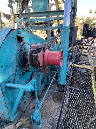
When a mud pump has entered full cavitation, rig crews and field service technicians will see the equipment shaking and hear the pump “knocking,” which typically sounds like marbles and stones being thrown around inside the equipment. However, the process of cavitation starts long before audible signs reveal themselves – hence the name “the silent killer.”
Mild cavitation begins to occur when the mud pump is starved for fluid. While the pump itself may not be making noise, damage is still being done to the internal components of the fluid end. In the early stages, cavitation can damage a pump’s module, piston and valve assembly.
The imperceptible but intense shock waves generated by cavitation travel directly from the fluid end to the pump’s power end, causing premature vibrational damage to the crosshead slides. The vibrations are then passed onto the shaft, bull gear and into the main bearings.
If not corrected, the vibrations caused by cavitation will work their way directly to critical power end components, which will result in the premature failure of the mud pump. A busted mud pump means expensive downtime and repair costs.
Washouts are one of the leading causes of module failure and take place when the high-pressure fluid cuts through the module’s surface and damages a sealing surface. These unexpected failures are expensive and can lead to a minimum of eight hours of rig downtime for module replacement.
To stop cavitation before it starts, install and tune high-speed pressure sensors on the mud suction line set to sound an alarm if the pressure falls below 30 psi.
Although the pump may not be knocking loudly when cavitation first presents, regular inspections by a properly trained field technician may be able to detect moderate vibrations and slight knocking sounds.
Gardner Denver offers Pump University, a mobile classroom that travels to facilities and/or drilling rigs and trains rig crews on best practices for pumping equipment maintenance.
Severe cavitation will drastically decrease module life and will eventually lead to catastrophic pump failure. Along with downtime and repair costs, the failure of the drilling pump can also cause damage to the suction and discharge piping.
When a mud pump has entered full cavitation, rig crews and field service technicians will see the equipment shaking and hear the pump ‘knocking’… However, the process of cavitation starts long before audible signs reveal themselves – hence the name ‘the silent killer.’In 2017, a leading North American drilling contractor was encountering chronic mud system issues on multiple rigs. The contractor engaged in more than 25 premature module washes in one year and suffered a major power-end failure.
Gardner Denver’s engineering team spent time on the contractor’s rigs, observing the pumps during operation and surveying the mud system’s design and configuration.
The engineering team discovered that the suction systems were undersized, feed lines were too small and there was no dampening on the suction side of the pump.
Following the implementation of these recommendations, the contractor saw significant performance improvements from the drilling pumps. Consumables life was extended significantly, and module washes were reduced by nearly 85%.
Although pump age does not affect its susceptibility to cavitation, the age of the rig can. An older rig’s mud systems may not be equipped for the way pumps are run today – at maximum horsepower.
It may be impractical to flush system piping during drilling operations. However, strainer screens should be checked daily to remove any debris or other flow restrictions.

The condenser water pumps take hot water from the condenser to the cooling tower, and the chilled water pumps take cold water from the chiller to your AC unit.
When the pump fails, water is not circulated as efficiently or at all, compromising the performance of your entire system. Thankfully, pumps often signal that there is something wrong, and these signals usually come in the form of odd and loud pump noises.
Loud and unusual sounds emanating from circulating pumps are always a red flag, a sign that something is wrong either with the pump or in the water lines.
Modern pumps have bleeder valves that make the process very easy. Slowly open the valve until you start hearing a hissing noise. Once the hissing ceases, you will see a slight dribble of water, indicating that the pump no longer has air. At this point, you can close the valve.
After doing this, make sure that the pump has been installed correctly. Even a few degrees of inclination or misalignment will allow air to get locked in the pump.
Pumps can be oversized for several reasons. It could happen due to a degree of error in the planning and design stage when engineers need to “guesstimate” piping length and fittings, or it could be purposely designed this way so the system can expand in the future and the “right-size” pump today would not be able to meet the future demand of tomorrow.
Sometimes a pump replacement is needed right away, and the supplier didn’t have the perfect replacement in stock, or the engineers choose an oversized pump already considering an expected build-up of corrosion in the pipes that require more pump head.
Regardless of the reason that led to an oversized pump, having one can always cause excessive noise and vibration, loosing up connections and joints and causing piping fatigue.
Under sizing a pump presents a more serious issue. That’s because you, unfortunately, don’t have much choice other than replacing the pump and installing a larger one.
If the system is undersized, it can’t provide the duty needed, it can also lead to deadheading - when a pump’s discharge is closed because of a blockage in the line or an unintentional closed valve. When this happens, the fluid churns inside the pump until it heats up into a vapor, causing noise and damage. Deadheaded pumps can lead to motor burn out, a damaged impeller, seal leakage, cracked bushings, and compromised elastomers, ultimately killing the pump.
In systems with undersized pumps, you can verify if the existing pump can handle a larger motor to avoid dead head. Even though it may be the cheapest way to handle the problem, it is not the best and the solution would just be temporary.
Only some pumps have bearing assemblies, not all. However, all electric pump motors have bearings, and the excessive wear of bearings – whether on the assembly or inside the motor - can cause pump noise.
The good news is that pump models with bearing assemblies usually have the components available for purchase, and they are inexpensive and easy to replace.
Water with rust and other sediments can wear out the circulating pump and clog the impeller. When this happens, noise is a consequence. To get rid of it, there is no magic bullet: the solution is in cleaning the system.
High-quality and modern pumps usually have 3 flow settings, while older pumps may have only one or two. That’s why older pumps are typically noisier than others. They are less efficient, and the energy loss is usually translated into a humming noise.
If your pump is making this noise and you have more than one option of flow setting to work with, locate the flow switch and turn it down one level. Then check the radiators and tower rails to verify if they are still getting up to the temperature they should. If so, then leave it this way.
If you operate with a VFD and your pump is still making a humming noise, check to see if you have a correct grounding of the motor to the VFD. In many cases, incorrect grounding allows the system to act as a noise transmitter.
To understand this, we need to take a step back and take a quick look at pump operation. Bernoulli"s principle shows us that fluid flows from areas of high pressure to areas of low pressure.
HVAC pumps operate by creating low pressure at the inlet, allowing the water to be pushed into the pump. As the fluid flows through the pump, the pressure decreases. If the pressure at the inlet happens to fall below the vapor pressure of the fluid, air bubbles form at the inlet. These bubbles can cause cavitation, leading to pump noise, damage, and lower capacity.
Net Positive Suction Head or NPSH is the difference between liquid pressure at the pump suction and liquid vapor pressure and is expressed in terms of the height of the liquid column. NPSH needs to be usually 3 to 5 feet to avoid cavitation.
If detected in an inspection that there’s a problem with the NPSH, basically two things can be done: first, there’s the option to choose a more appropriate pump for the application (our recommendation if the pump has already suffered irreparable damage due to cavitation). Second, the system can be reevaluated to see if elevating the cooling tower can increase NPSHa (the absolute pressure at the suction port of the pump) or if fittings that rob current NPSHa can be reduced.
If you need assistance with anything related to circulating pumps, contact us. We have 3 offices in California, and we can go wherever you are to inspect your pump if you are experiencing loud and unusual noises.
The Vertical Systems team of sales engineers and technicians can point out the cause of pump noises, and determine the best solution to eliminate it. Experts in all types of circulating pumps, our professionals can solve any problems with installation, worn components, leaks, and issues related to water temperature, pressure, and air bubbles. They can also recommend energy-efficient upgrades that will make your system perform better and save you money.

I felt the noise was coming from the pump, so I had them remove and disassemble the pump. We found one piston’s brass shoe worn down approximately 1/16 of an inch compared to the other apparently good pistons. We noticed the small lubrication hole was plugged with brass, possibly from the shoe wearing down on this piston. All the other piston lubrication holes were clear, and their shoes looked fine except for quite a few scratches on their face. The scratches were probably caused by the one piston’s wear material.
We checked the filters and found everything in good working order with the elements having been recently changed before the noise developed. There was a nick in the housing O-ring, but it didn’t leak when re-assembled. The HPU was a simple tank, pressure-compensated piston pump, safety relief, proportional valve, brake valve, and motor.
My first days as an MWD field tech I heard horror stories surrounding what is commonly referred to as “pump noise”. I quickly identified the importance of learning to properly identify this “noise”. From the way it was explained to me, this skill might prevent the company you work from losing a job with an exploration company, satisfy your supervisor or even allow you to become regarded as hero within your organization if you’ve proven yourself handy at this skill.
“Pump noise” is a reference to an instability in surface pressure created by the mud pumps on a modern drilling rig, often conflated with any pressure fluctuation at a similar frequency to pulses generated by a mud pulser, but caused by a source external to the mud pulser. This change in pressure is what stands in the way of the decoder properly understanding what the MWD tool is trying to communicate. For the better part of the first year of learning my role I wrongly assumed that all “noise” would be something audible to the human ear, but this is rarely the case.
In an ideal drilling environment surface pressure will remain steady and all pressure increases, and decreases will be gradual. This way, when the pulser valve closes(pulses), it’s easily detectable on surface by computers. Unfortunately drilling environments are rarely perfect and there are many things that can emulate a pulse thus causing poor or inaccurate data delivery to surface. The unfortunate circumstance of this means drilling operations must come to halt until data can once again be decoded on surface. This pause in the drilling process is commonly referred to at NPT or non-productive time. For those of you unfamiliar these concepts, I’ll explain some of the basics.
A mud pulser is a valve that briefly inhibits flow of drilling fluid traveling through the drill string, creating a sharp rise and fall of pressure seen on surface, also known as a “pulse”.
Depending on if the drilling fluid is being circulated in closed or open loop, it will be drawn from a tank or a plastic lined reservoir by a series(or one) mud pumps and channeled into the stand pipe, which runs up the derrick to the Kelly-hose, through the saver sub and down the drill-pipe(drill-string). Through the filter screen past an agitator or exciter, around the MWD tool, through a mud motor and out of the nozzles in the bit. At this point the fluid begins it’s journey back to the drilling rig through the annulus, past the BOP then out of the flow line and either over the shale shakers and/or back in the fluid reservoir.
Developing a firm grasp on these fundamentals were instrumental in my success as a field technician and an effective troubleshooter. As you can tell, there are a lot of components involved in this conduit which a mud pulser telemeters through. The way in which many of these components interact with the drilling fluid can suddenly change in ways that slightly create sharp changes in pressure, often referred to as “noise”. This “noise” creates difficulty for the decoder by suddenly reducing or increasing pressure in a manner that the decoder interprets a pulse. To isolate these issues, you must first acknowledge potential of their existence. I will give few examples of some of these instances below:
Suction screens on intake hoses will occasionally be too large, fail or become unfastened thus allowing large debris in the mud system. Depending on the size of debris and a little bit of luck it can end up in an area that will inhibit flow, circumstantially resulting in a sudden fluctuation of pressure.
Any solid form of drilling fluid additive, if improperly or inconsistently mixed, can restrict the flow path of the fluid resulting in pressure increase. Most notably this can happen at the pulser valve itself, but it is not the only possible outcome. Several other parts of this system can be affected as well. LCM or loss of circulation material is by far the most common additive, but the least overlooked. It’s important for an MWD technician to be aware of what’s being added into the drilling fluid regardless if LCM isn’t present. Through the years I have seen serval other improperly mixed additives cause a litany of pressure related issues.
This specifically is a term used to refer to the mud motor stator rubber deterioration, tearing into small pieces and passing through the nozzles of the bit. Brief spikes in pressure as chunks of rubber pass through one or more nozzles of the bit can often be wrongly interpreted as pulses.
Sometimes when mud is displaced or a pump suction isn’t completely submerged, tiny air bubbles are introduced into the drilling fluid. Being that air compresses and fluid does not, pulses can be significantly diminished and sometimes non-existent.
As many of you know the downhole mud motor is what enables most drilling rigs to steer a well to a targeted location. The motor generates bit RPM by converting fluid velocity to rotor/bit RPM, otherwise known as hydraulic horsepower. Anything downhole that interacts with the bit will inevitably affect surface pressure. One of the most common is bit weight. As bit weight is increased, so does surface pressure. It’s important to note that consistent weight tends to be helpful to the decoder by increasing the amplitude of pulses, but inconsistent bit weight, depending on frequency of change, can negatively affect decoding. Bit bounce, bit bite and inconsistent weight transfer can all cause pressure oscillation resulting in poor decoding. Improper bit speed or bit type relative to a given formation are other examples of possible culprits as well.
Over time mud pump components wear to the point failure. Pump pistons(swabs), liners, valves and valve seats are all necessary components for generating stable pressure. These are the moving parts on the fluid side of the pump and the most frequent point of failure. Another possible culprit but less common is an inadequately charged pulsation dampener. Deteriorating rubber hoses anywhere in the fluid path, from the mud pump to the saver sub, such as a kelly-hose, can cause an occasional pressure oscillation.
If I could change one thing about today’s directional drilling industry, it would be eliminating the term “pump noise”. The misleading term alone has caused confusion for countless people working on a drilling rig. On the other hand, I’m happy to have learned these lessons the hard way because they seem engrained into my memory. As technology improves, so does the opportunities for MWD technology companies to provide useful solutions. Solutions to aid MWD service providers to properly isolate or overcome the challenges that lead to decoding issues. As an industry we have come a lot further from when I had started, but there is much left to be desired. I’m happy I can use my experiences by contributing to an organization capable of acknowledging and overcoming these obstacles through the development of new technology.

Excessive or erratic hydraulic pump noise is a symptom of malfunction that could cause damage or accelerated wear if not addressed quickly and correctly. While it’s never nice to hear strange noises emitted from your pump, different forms of noise, which are related to different faults can provide valuable clues that can help you to diagnose your problem and get it fixed before it turns into something major.
So it pays to know what different pump noises mean and with practice you can quickly distinguish between the normal operating sounds and signs that something is wrong. In this article, we’ll talk about what causes some of these sounds, so you can identify them.
A constant hissing sound is indicative of a relief valve that is set too low or is stuck open and is continually releasing pressure. An erratic whistling sound is a symptom that a relief valve is set incorrectly or is damaged. It is common for pump settings to be changed carelessly or inadvertently - sometimes to overcome other issues with the hydraulic system - sometimes due to a lack of understanding of the correct operating conditions, so include this in your regular checks. In addition to noise problems, relief valve damage can be accompanied by slamming of actuators, stalls and excessive heat generation.
Noise issues are just one symptom that gives you a clue when things go wrong with your hydraulic pump. There are several other issues to know and understand, which could help you to identify pump problems quicker. Which means you can sort them out sooner - potentially saving big money down the road. These include heat problems, pressure problems and flow problems.

Measurement While Drilling tool is used to get realtime downhole data while drilling and used to make correct decision as soon as possible. The key to get realtime data is to decode the transmitted MWD signal on surface. Unable to decode transmitted signal may lead to loss of money, or even safety issue.
This article will focus on understanding of MWD signal decoding which is transmitted via mud pulse telemetry since this method of transmission is the most widely used commercially in the world.
As a basic idea, one must know that transmitted MWD signal is a wave that travels through a medium. In this case, the medium is mud column inside the drill string to mud pumps. Decoding is about detecting the travelling wave and convert it into data stream to be presented as numerical or graphical display.
The signal is produced by downhole transmitter in the form of positive pulse or negative pulse. It travels up hole through mud channel and received on the surface by pressure sensor. From this sensor, electrical signal is passed to surface computer via electrical cable.
On the way the signal leaves the transmitter, it experiences lots of disturbances that make the original signal distorted to various level, from minor distortion to severe distortion which makes decoding impossible. These disturbances are called noises.
Noise sources are bit, drill string vibration, bottom hole assemblies, signal reflection and mud pumps. Other than the noises, the signal is also dampened by the mud which make the signal becomes weak at the time it reaches the pressure sensor. Depth also weaken the signal strength, the deeper the depth, the weaker the signal detected.
Rock bit may create tri-lobe pattern. This pattern is created by the cones of the bit on the bottom of the hole. While drilling, the bit’s cones ride along this tri-lobe pattern and makes the bit bounce or known as axial vibration. As the bit bounces, back pressure is produced at the bit nozzles and transmitted to surface. The frequency of the noise created by bit bounce correlates with bit RPM. The formula to calculate its frequency is 3*(bit RPM)/60. When the bit bounce frequency match with MWD signal frequency, decoding is affected.
BHA components that have moving mechanical parts such as positive mud motor and agitator create noise at certain frequency. The frequency produced by these assemblies depends on the flow rate and the lobe configuration. The higher the flow rate and the higher the lobe configuration creates higher noise frequency.
Thruster, normally made up above MWD tool, tends to dampen the MWD signal significantly. It has a nozzle to use mud hydraulic power to push its spline mandrel – and then push the BHA components beneath it including the bit – against bottom of the hole. When the MWD signal is passing through the nozzle, the signal loses some of its energy. Weaker signal will then be detected on surface.
When the wave hits a solid surface like a pipe bend or a closed valve the wave will be reflected backward against the direction of original MWD signal as described in figure 2 below.
The pressure sensor on the pipe manifold detects 2 identical signals, one from the original MWD transmitter and another one comes from signal reflection, which are separated in some milliseconds. The result seen by the surface computer is the sum of those two signals. Depending on the individual signal width and the timing when the reflected signal arrives at the pressure sensor, surface computer may see a wider signal width or two identical signals adjacent to each other.
The common sources of signal reflection are pipe bending, change in pipe inner diameter or closed valve. These are easily found in pipe manifold on the rig floor. To avoid the signal reflection problem, the pressure sensor must be mounted in a free reflection source area, for example close to mud pumps. The most effective way to solve this problem is using dual pressure sensors method.
Mud pump is positive displacement pump. It uses pistons in triplex or duplex configuration. As the piston pushes the mud out of pump, pressure spikes created. When the piston retracts, the pressure back to idle. The back and forth action of pistons produce pressure fluctuation at the pump outlet.
Pressure fluctuation is dampened by a dampener which is located at the pump outlet. It is a big rounded metal filled with nitrogen gas and separated by a membrane from the mud output. When the piston pushes the mud the nitrogen gas in the dampener will be compressed storing the pressure energy; and when the piston retracts the compressed nitrogen gas in the dampener release the stored energy. So that the output pressure will be stable – no pressure fluctuation.
The dampener needs to be charged by adding nitrogen gas to certain pressure. If the nitrogen pressure is not at the right pressure, either too high or too low, the pump output pressure fluctuation will not be stabilized. This pressure fluctuation may match the MWD frequency signal and hence it disturbs decoding, it is called pump noise.
When the pump noise occurs, one may simply change the flow rate (stroke rate) so that the pump noise frequency fall outside the MWD frequency band – and then apply band pass frequency to the decoder.
The formula to calculate pump noise frequency is 3*(pump stroke rate)/60 for triplex pump and 2*(pump stroke rate)/60 for duplex pump. The rule of thumb to set up dampener pressure charge is a third (1/3) of the working standpipe pressure.
Sometime the MWD signal is not detected at all when making surface test although the MWD tool is working perfectly. This happen whenever the stand pipe pressure is the same with the pump dampener pressure. Reducing or increasing test flow rate to reduce or increase stand pipe pressure helps to overcome the problem.
When the MWD signal wave travels through mud as the transmission medium, the wave loses its energy. In other words, the wave is giving some energy to the mud.
The mud properties that are affecting MWD signal transmission is viscosity and weight. The increasing mud weight means there is more solid material or heavier material in the mud. Sometimes the mud weight increment is directly affecting mud viscosity to become higher. The MWD signal wave interacts with those materials and thus its energy is reduced on its way to surface. The more viscous the mud and the heavier the mud, the weaker the signal detected on surface.
Aerated mud often used in underbalance drilling to keep mud influx into the formation as low as possible. The gas injected into the mud acts as signal dampener as gas bubble is compressible. MWD signal suffers severely in this type of mud.
Proper planning before setting the MWD pulser gap, flow rate and pump dampener pressure based on mud properties information is the key to overcome weak signal.
The further the signal travels, the weaker the signal detected on the surface. The amount of detected signal weakness ratio compare to the original signal strength when it is created at the pulser depends on many factors, for example, mud properties, BHA component, temperature and surface equipment settings.
Rigging up sensor cables especially on the offshore rig is challenging since the cables must not create safety hazard to other people and equipment’s. Most of the time the cables must be run alongside rig’s high voltage electrical cables. The high voltage may induce sensor cables which creates continuous or temporal spiky signal in the surface decoder.

Researchers have shown that mud pulse telemetry technologies have gained exploration and drilling application advantages by providing cost-effective real-time data transmission in closed-loop drilling operations. Given the inherited mud pulse operation difficulties, there have been numerous communication channel efforts to improve data rate speed and transmission distance in LWD operations. As discussed in “MPT systems signal impairments”, mud pulse signal pulse transmissions are subjected to mud pump noise signals, signal attenuation and dispersion, downhole random (electrical) noises, signal echoes and reflections, drillstring rock formation and gas effects, that demand complex surface signal detection and extraction processes. A number of enhanced signal processing techniques and methods to signal coding and decoding, data compression, noise cancellation and channel equalization have led to improved MPT performance in tests and field applications. This section discusses signal-processing techniques to minimize or eliminate signal impairments on mud pulse telemetry system.
At early stages of mud pulse telemetry applications, matched filter demonstrated the ability to detect mud pulse signals in the presence of simulated or real noise. Matched filter method eliminated the mud noise effects by calculating the self-correlation coefficients of received signal mixed with noise (Marsh et al. 1988). Sharp cutoff low-pass filter was proposed to remove mud pump high frequencies and improve surface signal detection. However, matched filter method was appropriate only for limited single frequency signal modulated by frequency-shift keying (FSK) with low transmission efficiency and could not work for frequency band signals modulated by phase shift keying (PSK) (Shen et al. 2013a).
Wavelet transform method was developed and widely adopted and used in signal processing to overcome limitation of Fourier transform in time domain (Bultheel 2003). Although Fourier and its revised fast Fourier transforms are powerful mathematical tool, they are not very good at detecting rapid changes in signals such as seismic data and well test data in petroleum industry containing many structure of different scales (Multi-scale structures) (Guan et al. 2004). Fourier coefficients do not provide direct information about the signal local behavior (localization); but the average strength of that frequency in the full signal as the sine or cosine function keeps undulating to infinity. Wavelet transform analyzes the signal frequency components and time segment, and fine tune sampling of localized characters of time or frequency domain. Principles of wavelet transform and de-noising technique show that signal can be divided into space and scale (time and frequency) without losing any useful information of the original signal, hence ensuring the extraction of useful information from the noised signal (Li et al. 2007). Different wavelet base parameters constructed, such as haar, db, coif, sym, bior, rbio and dmey, are suitable for different signal processing requirements. The small the scale parameter is, the higher the resolving power in frequency, suitable for processing high frequency signals; conversely, the larger the scale is the higher resolving power suitable for low frequency signal.
In processing noise-contaminated mud pulse signals, longer vanishing moments are used, but takes longer time for wavelet transform. The main wavelet transform method challenges include effective selection of wavelet base, scale parameters and vanishing moment; the key determinants of signal correlation coefficients used to evaluate similarities between original and processed signals. Chen et al. (2010) researched on wavelet transform and de-noising technique to obtain mud pulse signals waveform shaping and signal extraction based on the pulse-code information processing to restore pulse signal and improve SNR. Simulated discrete wavelet transform showed effective de-noise technique, downhole signal was recovered and decoded with low error rate. Namuq et al. (2013) studied mud pulse signal detection and characterization technique of non-stationary continuous pressure pulses generated by the mud siren based on the continuous Morlet wavelet transformation. In this method, generated non-stationary sinusoidal pressure pulses with varying amplitudes and frequencies used ASK and FSK modulation schemes. Simulated wavelet technique showed appropriate results for dynamic signal characteristics analysis.
As discussed in “MPT mud pump noises”, the often overlap of the mud pulses frequency spectra with the mud pump noise frequency components adds complexity to mud pulse signal detection and extraction. Real-time monitoring requirement and the non-stationary frequency characteristics made the utilization of traditional noise filtering techniques very difficult (Brandon et al. 1999). The MPT operations practical problem contains spurious frequency peaks or outliers that the standard filter design cannot effectively eliminate without the possibility of destroying some data. Therefore, to separate noise components from signal components, new filtering algorithms are compulsory.
Early development Brandon et al. (1999) proposed adaptive compensation method that use non-linear digital gain and signal averaging in the reference channel to eliminate the noise components in the primary channel. In this method, synthesized mud pulse signal and mud pump noise were generated and tested to examine the real-time digital adaptive compensation applicability. However, the method was not successfully applied due to complex noise signals where the power and the phases of the pump noises are not the same.
Jianhui et al. (2007) researched the use of two-step filtering algorithms to eliminate mud pulse signal direct current (DC) noise components and attenuate the high frequency noises. In the study, the low-pass finite impulse response (FIR) filter design was used as the DC estimator to get a zero mean signal from the received pressure waveforms while the band-pass filter was used to eliminate out-of-band mud pump frequency components. This method used center-of-gravity technique to obtain mud pulse positions of downhole signal modulated by pulse positioning modulation (PPM) scheme. Later Zhao et al. (2009) used the average filtering algorithm to decay DC noise components and a windowed limited impulse response (FIR) algorithm deployed to filter high frequency noise. Yuan and Gong (2011) studied the use of directional difference filter and band-pass filter methods to remove noise on the continuous mud pulse differential binary phase shift keying (DBPSK) modulated downhole signal. In this technique, the directional difference filter was used to eliminate mud pump and reflection noise signals in time domain while band-pass filter isolated out-of-band noise frequencies in frequency domain.
Other researchers implemented adaptive FIR digital filter using least mean square (LMS) evaluation criterion to realize the filter performances to eliminate random noise frequencies and reconstruct mud pulse signals. This technique was adopted to reduce mud pump noise and improve surface received telemetry signal detection and reliability. However, the quality of reconstructed signal depends on the signal distortion factor, which relates to the filter step-size factor. Reasonably, chosen filter step-size factor reduces the signal distortion quality. Li and Reckmann (2009) research used the reference signal fundamental frequencies and simulated mud pump harmonic frequencies passed through the LMS filter design to adaptively track pump noises. This method reduced the pump noise signals by subtracting the pump noise approximation from the received telemetry signal. Shen et al. (2013a) studied the impacts of filter step-size on signal-to-noise ratio (SNR) distortions. The study used the LMS control algorithm to adjust the adaptive filter weight coefficients on mud pulse signal modulated by differential phase shift keying (DPSK). In this technique, the same filter step-size factor numerical calculations showed that the distortion factor of reconstructed mud pressure QPSK signal is smaller than that of the mud pressure DPSK signal.
Study on electromagnetic LWD receiver’s ability to extract weak signals from large amounts of well site noise using the adaptive LMS iterative algorithm was done by (Liu 2016). Though the method is complex and not straightforward to implement, successive LMS adaptive iterations produced the LMS filter output that converges to an acceptable harmonic pump noise approximation. Researchers’ experimental and simulated results show that the modified LMS algorithm has faster convergence speed, smaller steady state and lower excess mean square error. Studies have shown that adaptive FIR LMS noise cancellation algorithm is a feasible effective technique to recover useful surface-decoded signal with reasonable information quantity and low error rate.
Different techniques which utilize two pressure sensors have been proposed to reduce or eliminate mud pump noises and recover downhole telemetry signals. During mud pressure signal generation, activated pulsar provides an uplink signal at the downhole location and the at least two sensor measurements are used to estimate the mud channel transfer function (Reckmann 2008). The telemetry signal and the first signal (pressure signal or flow rate signal) are used to activate the pulsar and provide an uplink signal at the downhole location; second signal received at the surface detectors is processed to estimate the telemetry signal; a third signal responsive to the uplink signal at a location near the downhole location is measured (Brackel 2016; Brooks 2015; Reckmann 2008, 2014). The filtering process uses the time delay between first and third signals to estimate the two signal cross-correlation (Reckmann 2014). In this method, the derived filter estimates the transfer function of the communication channel between the pressure sensor locations proximate to the mud pump noise source signals. The digital pump stroke is used to generate pump noise signal source at a sampling rate that is less than the selected receiver signal (Brackel 2016). This technique is complex as it is difficult to estimate accurately the phase difference required to give quantifiable time delay between the pump sensor and pressure sensor signals.
As mud pulse frequencies coincide with pump noise frequency in the MPT 1–20 Hz frequency operations, applications of narrow-band filter cannot effectively eliminate pump noises. Shao et al. (2017) proposed continuous mud pulse signal extraction method using dual sensor differential signal algorithm; the signal was modulated by the binary frequency-shift keying (BFSK). Based on opposite propagation direction between the downhole mud pulses and pump noises, analysis of signal convolution and Fourier transform theory signal processing methods can cancel pump noise signals using Eqs. 3 and 4. The extracted mud pulse telemetry signal in frequency domain is given by Eqs. 3 and 4 and its inverse Fourier transformation by Eq. 4. The method is feasible to solve the problem of signal extraction from pump noise,
$$s(t)={f^{ - 1}}S(\omega )={f^{ - 1}}\left[ {\frac{{{P_{\text{A}}}(\omega ) - H(\omega ){P_{\text{B}}}(\omega )}}{{1 - H(\omega )H(\omega )}}} \right],$$
These researches provide a novel mud pulse signal detection and extraction techniques submerged into mud pump noise, attenuation, reflections, and other noise signals as it moves through the drilling mud.

A well-placed suction stabilizer can also prevent pump chatter. Pump chatter occurs when energy is exchanged between the quick opening and closing of the reciprocating pump’s valves and the hammer effect from the centrifugal pump. Pump isolation with suction stabilizers is achieved when the charge pumps are isolated from reciprocating pumps and vice versa. The results are a smooth flow of pumped media devoid of agitating energies present in the pumped fluid.
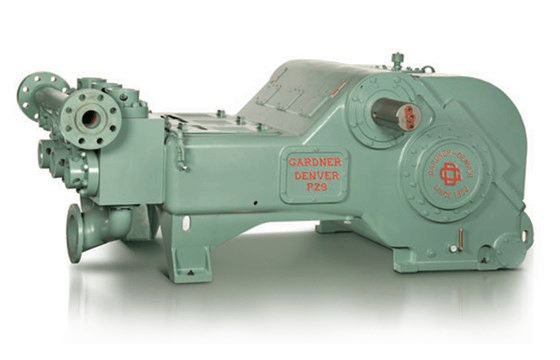
A mud pump is a piston driven pump design that can produce high-pressure operations to safely transfer high viscosity fluids over an extended depth. The mud pump has many applications in industrial service, but it has proven to be invaluable in many drilling operations. Let"s take a look at mud pumps and why they are such a good fit for the industries they serve.
A Mud pump is a reciprocal pump design utilizing a piston in a cylinder to transfer fluids under high pressure. A mud pump can generate up to 7,500 psi (52,000 kPa) during normal operations. Mud pumps are a positive displacement design.
Mud pumps are available in a variety of configurations and sizes. However, mud pumps tend to be one of two main types: the duplex and the triplex. The duplex mud pump features two pistons (or plungers) in constant action to move the fluid.
The triplex mud pump has all but replaced the duplex version in most applications, although you will still find the latter in use in some smaller countries. The triplex mud pump features a triple piston (plunger) design that is more efficient than the duplex design.
The latest designs of the mud pump are the quintuplex and hex versions. As the name suggests, these designs feature five or six pistons in a reciprocating design. Although not in widespread use as compared to the triplex design, these mud pumps spread the pumping action across the rotational cycle, creating less mud noise. This allows for better measurements and logging to take place while in operation.
There are two main parts to a mud pump: the fluid end and the power end. The fluid end is where the actual pumping takes place. The components of the fluid end consist of valves, pistons (or plungers), and liners.
Since the fluid end is in constant contact with the material being pumped, most modern designs allow for quick replacement of worn components as needed. This dramatically extends the life of a unit without having to completely replace the pump.
The power end of a mud pump is responsible for taking the input power, typically through a driveshaft, and converting it into the reciprocating motion needed for the pistons. In most mud pump applications, the power end uses a crosshead crankshaft for this conversion.
Rotational power is supplied to the mud pump through an external power source. The power end of the pump converts this rotational energy through a crankshaft to a reciprocating motion that moves the pistons.
Due to the pressure and material being pumped, most mud pump applications can create a lot of vibration. To combat this, many mud pump applications incorporate pulsation dampeners. These are typically used on both suction and discharge sides of the pump.
In some cases, a positive displacement pump may pull the fluids at a pressure lower than its vapor pressure. When this happens, damaging cavitation can take place. In these cases, a charge pump might be required at the inlet side to maintain a positive pressure on the suction stream.
When selecting a mud pump, there are two main parameters to be used, pressure and displacement. Pressure is the net pumping pressure that the pump can safely provide. The requirement for pressure increases as the drilling depth and fluid (or slurry) viscosity increases.
Displacement is the volume of fluid that the pump can transfer within a given time period. In most applications, this is rated as discharged liters per minute.
Mud pumps are ideal wherever a lot of fluid needs to be pumped under high pressure. They are considered an essential part of most oil well drilling rigs. Mud pumps can deliver high concentration and high viscosity slurry in a stable flow, making them adaptable to many uses.
Mud pumps are an invaluable tool when high pressure and high viscosity fluids are needing to be transferred. Mader Electric, Inc. specializes in mud pump repair and installation, as well as pump training. Contact us to see how we can help with your pumping needs.

The present invention relates to drilling fluid telemetry systems, and, more particularly, to a system and method for reducing pump noise in a received telemetry signal.
Drilling fluid telemetry systems, generally referred to as mud pulse systems, are particularly adapted for telemetry of information from the bottom of a borehole to the surface of the earth during oil well drilling operations. The information telemetered often includes, but is not limited to, operational parameters, such as, pressure, temperature, direction and deviation of the wellbore. Other parameter include logging data such as resistivity of the various layers, sonic density, porosity, induction, self potential and pressure gradients related to the reservoirs surrounding the wellbore. This information is critical to efficiency in the drilling operation and economic production of the reservoirs.
A number of different pulser types are known to those skilled in the art. These include, but are not limited to, poppet pursers for generating positive or negative pressure pulses; siren pursers for generating continuous wave pulse signals; and rotationally oscillating shear-valve pursers that may generate discrete pulses and/or continuous wave signals. Various encoding techniques are known in the art for transmitting data utilizing the described pulse signals. In general, all of these systems generate a pressure pulse by blocking or venting a portion of the drilling fluid flowing in the drill string to the bit. The generated pulse propagates to the surface where it is detected and decoded for further use. A major source of noise in the detected signal is a result of the large pressure pulses associated with the use of positive displacement, plunger type pumps utilized for pumping the drilling fluid through the system. Such pumps commonly generate pressure pulses 1-2 orders of magnitude greater than the detected pressure signals at the point of signal detection. In addition, the pump frequency is commonly within the range of the pulsed signal frequency.
The system and method of the present invention operate to reduce the pump noise in the received signal and provide enhanced signal detection and reliability. SUMMARY OF THE INVENTION
One embodiment of the invention is a method of communicating a signal between a downhole location and a surface location. A pulsed variation is produced in a borehole fluid at the downhole location. A signal is measured at the surface location responsive to the pulsed variation. A frequency corresponding to at least one pump coupled to the mud channel is determined from the signal. A noise associated with the at least one pump is represented by a harmonic series including the determined frequency. The signal is adaptively filtered using the noise representation. The pulsed variation may be a pressure variation on a flow-rate variation. The pulsed variation may be representative of a property of the earth formation, and the method may further include making a measurement of the property using a formation evaluation sensor. The method may further include displaying the estimate of the property and/or distorting the estimate of the property on a suitable medium. Filtering of the signal may be done using a finite impulse response filter.
Another embodiment of the invention is an apparatus for communicating a signal from a downhole location to a surface location. The apparatus includes a signal source configured to produce a pulsed variation in a borehole fluid at the downhole location. The apparatus further includes a sensor at the surface location configured to produce a signal responsive to the pulsed variation. A processor is configured to determine from the signal a frequency corresponding to at least one pump coupled to the borehole fluid. The processor is further configured to represent a noise associated with the at least one pump by a harmonic series, and to adaptively filter the signal using the harmonic series and provide an estimate of the pulsed variation. The pulsed variation may be a pressure variation and/or a flow-rate variation. The apparatus may further include a formation evaluation sensor configured to make it measurement of the property of the earth formation, and the pulsed variation may be representative of the property of the formation. The processor may be further configured to use the estimate of the pulsed variation and provide an estimate of the property. The processor may be further configured to display the estimate of the property and/or store the estimate of the property on a suitable medium. The processor may be configured to filter the signal by using a finite impulse response filter.
Another embodiment of the invention is a computer-readable medium for use with an apparatus for communicating a signal from a downhole location to a surface location. The apparatus includes a signal source configured to produce a pulsed variation in a borehole fluid at a downhole location. The apparatus further includes a sensor at a surface location configured to produce a signal responsive to the pulsed variation. The medium includes instructions which enable a processor to determine from the signal a frequency corresponding to the at least one pump coupled to the borehole fluid, represent a noise associated with the at least one pump by a harmonic series, and adaptively filter the signal using the harmonic series and provide an estimate of the pulse variation. The medium may include a ROM, an EPROM, an EAROM, a flash memory, and/or an optical disk.
Another embodiment of the invention is a method of communicating between a downhole location and a surface location by producing pulsed variation in a borehole fluid at the downhole location. A signal is measured at the surface location responsive to the pulsed variation. A frequency corresponding to at least one pump coupled to the borehole fluid is determined from the measured signal in a frequency domain. An improved estimate of the frequency corresponding to the at least one pump is obtained in a time domain. The pulsed variation is filtered using the improved estimate of frequency corresponding to the at least one pump. The pulsed variation may be representative of a property of the earth formation, and a method may further include making a measurement of the property using a formation evaluation sensor. The method may further comprise processing the estimate of the pulse variation and providing an estimate of the property. The method may further include displaying the estimate of the property and/of storing the estimate of the property on a suitable medium. The pulsed variation may be representative of the condition of a bottomhole assembly in a borehole and thr method may further include measuring the condition of a bottomhole assembly.
Another embodiment of the invention is an apparatus for communicating between a downhole location and a surface location. The apparatus includes a signal source configured to produce a pulsed variation in a borehole fluid at a downhole location. The apparatus further includes a sensor configured to measure a signal at a surface location responsive to the pulsed variation. The apparatus also includes a processor configured to determine, in a frequency domain, a frequency corresponding to at least one pump coupled to the borehole fluid, obtain an improved estimate of the frequency corresponding to the at least one pump using a time domain method, and filter the signal using the improved estimate of frequency and an output of a timing signal generator operatively coupled to the at least one pump. The pulsed variation may be representative of the property of the earth formation and the apparatus may further include a formation evaluation sensor configured to make a measurement of the property. The processor may further be configured the use of the estimate of the pulsed variation and provide an estimate of the property. The processor may further be configured to display the estimate of the property and/of store the estimate of the property on a suitable medium. The pulsed variation may be representative of a condition of a bottomhole assembly and the apparatus may further include sensor configured to make the measurement of the property.
Another embodiment of the invention is a computer readable medium for use with an apparatus for communicating between a downhole location and a surface location, the apparatus including a signal source configured to produce a pulsed variation in a borehole in fluid at the downhole location, and a sensor at the surface location configured to measure a signal responsive to the pulsed variation. The medium includes instructions which enable a processor to determine in a frequency domain a frequency corresponding to at least one pump coupled to the borehole fluid, obtain an improved estimate of the frequency corresponding to the at least one pump using a time domain method, and filter the signal using the improved estimate of the frequency and an output of a timing signal generator operatively coupled to the at least one pump. BRIEF DESCRIPTION OF THE DRAWINGS
FIG. 1 is a schematic diagram showing a drilling rig 1 engaged in drilling operations. Drilling fluid 31, also called drilling mud, is circulated by pump 12 through the drill string 9 down through the bottom hole assembly (BHA) 10, through the drill bit 11 and back to the surface through the annulus 15 between the drill string 9 and the borehole wall 16. Commonly, pump 12 is a positive displacement pump, such as a triplex plunger pump. As one skilled in the art will appreciate, such a pump causes pressure spikes in the drilling fluid with a fundamental frequency related to the RPM of the pump driver. The BHA 10 may comprise any of a number of sensor modules 17, 20, 22 which may include, for example, formation evaluation sensors and directional sensors. These sensors are well known in the art and are not described further. The BHA 10 also contains a pulser assembly 19 which induces pressure fluctuations in the mud flow. The pressure fluctuations, or pulses, propagate to the surface through the mud flow in the drill string 9 and are detected at the surface by a sensor 18 and a control unit 24. Control unit 24 includes, but is not limited to, electronic circuits for interfacing with sensor 18 and a processor and memory for executing instructions related recovering signals transmitted by pulser 19. The sensor 18 is connected to the flow line 13 and may comprise at least one of a pressure sensor, a flow sensor, and a combination of a pressure sensor and a flow sensor. As one skilled in the art will appreciate, the pressure pulse has an associated fluid velocity pulse that also propagates through the drilling fluid and may be detected and decoded. It should be noted that instead of pressure variations, a pulser can be used to generate flow rate variations. Collectively, such pressure variations and flow rate variations are referred to as pulsed variations.
The present invention comprises a system and a method for pump noise cancellation (PNC) in mud pulse telemetry. As used herein, the term pump noise cancellation means a substantial reduction of pump noise in the detected telemetry signal. The system is able to identify one or more fundamental frequencies of harmonic pump noise in a received pressure pulse telemetry signal, based on certain operational input information. The operational input information includes, but is not limited to: the number of pumps; the expected operating frequency of the pumps; and the number of harmonics to remove. A reference signal containing the identified fundamental frequencies and their harmonics is generated to simulate the harmonic pump noise. The reference signal, along with the received telemetry signal, is passed through an adaptive least mean square (LMS) filter system, where the pump noise can be adaptively tracked. After successive adaptive iterations, the output of the LMS filter converges to an acceptable approximation of the harmonic pump noise in the LMS sense. Finally, a pump noise reduced signal is obtained by subtracting the pump noise approximation from the received telemetry signal.
In one embodiment, the automated PNC technique, see FIG. 2, comprises instructions in a processor in control unit 24. The instructions include, but are not limited to, three modules for recovering the transmitted pulse signal: (i) pre-processing 110; (ii) adaptive PNC 120; and (iii) post-processing 130. The nature of the signal sensed from sensor 18 depends on the type of sensor used. For example, if sensor 18 is a total pressure sensor, then the signal from sensor 18 commonly contains a static pressure component, representing the baseline pump pressure, as well as a dynamic component, representing the encoded pressure pulses and the pump generated noise. The static pressure signal is immaterial to the telemetry function and is commonly removed for detection of the pulses. The telemetry signal 101 from sensor 18 is initially processed 102 to remove static pressure, also called DC component, so as to perform further processing on substantially only the pressure pulse. The removal of the DC component may be done in either analog circuitry or done digitally.
Operating information (e.g., given frequency ranges where the fundamental frequencies likely appear) 103 is input into the system. In one embodiment the system determines the fundamental frequencies of the telemetry signal 104, by using, for example, Fourier transforms, on the telemetry signal 101. While the operating system could identify the fundamental frequencies obtained from other sources, this searching technique has an advantage of tolerating drifts of the fundamental frequencies. Such drift is common, for example, as the pump operating speed may drift causing a drift in the fundamental pump frequency. The pump noise at the fundamental frequency typically appears as a large-amplitude spike in the calculated frequency spectrum. The system searches for a maximum value in the given frequency range, and identifies the frequency corresponding to this maximum value as the fundamental frequency. For multiple fundamental frequencies, for example for multiple pumps, the system may search for more than one spike in the given frequency range, or one spike in each of multiple given frequency ranges.
A reference noise signal 106 is generated 105 using the determined fundamental noise frequencies. Assuming that the pump noise is harmonic, the following mathematical model is used for the reference noise signal 106,
where f0,l(for l=1,2, . . . L) are L fundamental frequencies of pump noises, K is the total number of harmonics to be used for the noise cancellation, and Ak,l, Bk,l, θk,land φk,l(for l=1,2, . . . L and k=1,2, . . . K) are initial amplitude and phase constant numbers for sinusoid signals, respectively.
In one aspect of the adaptive PNC module, the LMS adaptive algorithm may be used to suppress harmonic pump noises. In general, the adaptive filter 107 and the LMS algorithm 108 aim to minimize the mean square error (MSE) of a signal estimate by iteratively adjusting a set of adaptive filter coefficients. Three basic operations for the LMS algorithm are as follows:
where {right arrow over (w)}[n]={w0[n],w1[n], . . . , wM−1[n]}Tcontains the adaptive filter coefficients, {right arrow over (x)}[n]={x[n],x[n−1, . . . ,x[n−M+1]]}Tis the filter input, ŷ[n] is the filter output, y[n] is the desired signal, e[n] is the error signal as deviation of ŷ[n] from y[n], and μ is an adaptation constant (or stepsize). Superscript H represents a complex conjugate transpose, superscript * represents a complex conjugate, superscript T represents a real transpose, constant M is the filter length, and n is time index.
In one embodiment, the adaptive filter 107, {right arrow over (w)}[n], is a finite impulse response (FIR) filter. An FIR filter provides inherent stability and linear phase properties. The filter length, M, is one of the design parameter for using the LMS algorithm. Also, note that equations (2)-(4) indicate the adaptive filter outputs at time n depend not only on the inputs at time n, but also the inputs at the times n−1 until n−M+1. For a causal system, these inputs are totally or partly not available when n=0,1 . . . , M−2, and are typically set to zeros in practical applications. Another key design parameter for the LMS algorithm is the adaptive stepsize, μ. In general, in order to guarantee the convergence of the LMS adaptation algorithm, μ has to satisfy the following condition,
In post-processing module 130, the DC component of input telemetry signal 101 is added back to obtain the final pump noise-cancelled telemetry signal 133. In some cases only low-frequency components of the signal are of interest, and a low-pass filter 132 can be applied to the pump noise-cancelled signal.
The automated PNC system described in FIG. 2 is able to operate substantially autonomously after operating system parameters 103 are initially set up. The system processes a certain size of telemetry data each time. As new telemetry data come in, the system can update the PNC results every N≧1 samples. This updating includes searching for new fundamental frequencies of the pump noises, generating new reference noise signals, and updating the adaptive filter coefficients. It is because of this updating that the system is able to track the drifting of the fundamental frequencies. The system operates in real time when every sample is updated. If updating is done every N>1 samples, the system has a time delay of N samples. This procedure can be thought of as a sliding window operation. The window size, W, is equal to the size of currently processed telemetry data, and the shifting stepsize of the window, s, is equal to N. At the very beginning of the operation, the system waits for W samples to start the automated PNC operation. After this waiting period, the system can operates in real time (s=N=1) or, alternatively, with a time delay of s=N>1 samples. Note that the adaptive LMS filter outputs at times n=0,1 . . . ,M−2 are not reliable. To avoid this problem, the sliding window is extended to include previous M−1 samples for the system input, but to neglect the first M−1 samples in the system output.
Regarding the window size, first, a longer window results in longer system delay, which is usually not allowable in practical telemetry applications. Second, a shorter window degrades the spectral resolution and thus the accuracy of the fundamental frequency determination in the pre-processing module. Moreover, a shorter window reduces the number of adaptive iterations and thus the accuracy of harmonic pump noise estimates in the adaptive PNC module. Therefore, the window size is chosen according to the requirements of the telemetry application.
FIGS. 3 and 4 show the automated PNC method as tested on two sets of real telemetry data contaminated by pump noises. Sampling rates for the two sets of data are 64 Hz (FIG. 3) and 1000 Hz (FIG. 4), respectively. Pulse width is 0.8 seconds for both data sets. All the initial parameters for the system have been empirically determined and summarized in Table II. Primary testing results are shown in FIGS. 3 and 4, where the investigated data length is 8 seconds. The upper part of each figure shows the raw telemetry signals 301 and 401 and the pump noise-cancelled signals 302 and 402 in the time domain. The lower part shows their Fourier spectra indicating that in the raw telemetry signals, there is significant pu


 8613371530291