
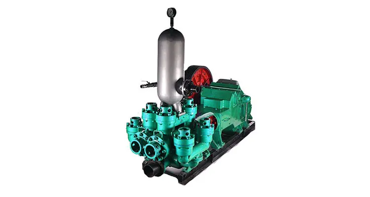
duplex double acting mud pump free sample
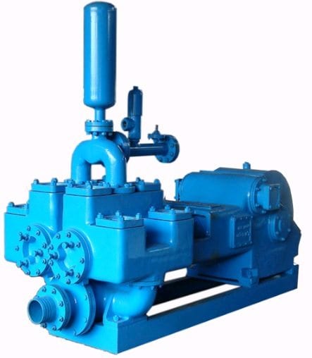
A mud pump is a reciprocating piston/plunger pump designed to circulate drilling fluid under high pressure (up to 7,500 psi (52,000 kPa)) down the drill string and back up the annulus. A duplex mud pump is an important part of the equipment used for oil well drilling.
Duplex mud pumps (two piston/plungers) have generally been replaced by the triplex pump, but are still common in developing countries. Two later developments are the hex pump with six vertical pistons/plungers, and various quintuplex’s with five horizontal piston/plungers. The advantages that Duplex mud pumps have over convention triplex pumps is a lower mud noise which assists with better Measurement while drilling and Logging while drilling decoding.
Use duplex mud pumps to make sure that the circulation of the mud being drilled or the supply of liquid reaches the bottom of the well from the mud cleaning system. Despite being older technology than the triplex mud pump, the duplex mud pumps can use either electricity or diesel, and maintenance is easy due to their binocular floating seals and safety valves.
A mud pump is composed of many parts including mud pump liner, mud pump piston, modules, hydraulic seat pullers, and other parts. Parts of a mud pump:housing itself
Duplex pumps are used to provide a secondary means of fuel transfer in the event of a failure of the primary pump. Each pump in a duplex set is sized to meet the full flow requirements of the system. Pump controllers can be set for any of the following common operating modes:Lead / Lag (Primary / Secondary): The lead (primary) pump is selected by the user and the lag (secondary pump operates when a failure of the primary pump is detected.
Alternating: Operates per Lead / Lag (Primary / Secondary) except that the operating pump and lead / lag status alternate on consecutive starts. A variation is to alternate the pumps based on the operating time (hour meter) of the lead pump.

This invention relates generally to piston pumps for the water well drilling industry, and more particularly to a hydraulic cylinder powered double acting duplex piston pump.
Double acting duplex piston pumps are well known and have been used in the water well drilling industry for many years. Typically they employ a crankshaft and flywheel driven in various ways, a reciprocating engine or a hydraulic motor being examples. Typically, they are heavy units with a large component of cast iron. Today"s well drilling trucks carry lengths of drilling pipe, as well as derricks, motors, pumps of various kinds, and the “mud” pump. The current double acting duplex piston pumps with crankshaft and flywheel, being very heavy, contribute significantly to the weight and space requirements of the truck. They impact the ability of a truck to meet federal highway weight restrictions. Also, the mechanical crank throw design imparts a variable speed to the mud pump piston. In such designs, the piston is either accelerating or decelerating during a large part of its design stroke. So the piston operates at its full design capacity during only a portion of the stroke. Therefore, it is an object of the present invention to provide a duplex piston pump useful as a mud pump on a water well drilling machine, but without a motor, crankshaft, flywheel, gearing, and/or belts, for a significant weight reduction.
Described briefly, according one embodiment of the present invention, a mud pump is provided with two working cylinders for pumping mud, and two sets of double-acting hydraulic driving cylinders. One set of two driving cylinders has the piston of each connected to the piston of one double-acting mud pump cylinder. The other set of two driving cylinders has the piston of each connected to the piston of the other double-acting mud pump cylinder. The connection of a set of driving cylinder pistons to the mud pump piston is through a member which allows side-by-side, or over and under parallel arrangement of the driving cylinders and mud pump cylinders, so the overall length is minimal. An electro-hydraulic control system is provided to coordinate the action of the pump driving cylinders with the mud pumping cylinders for contributing to steady flow of mud from the mud pump.
FIG. 2 is a schematic elevational view of one of the two pump assemblies of the duplex piston pump according to one embodiment of the present invention.
FIG. 3 is a schematic diagram of a system according to the illustrated embodiment and showing both of the duplex mud pump cylinders, with one of two hydraulic driving cylinders for each of the mud pump cylinders, and including an organization of hydraulic flow divider, rod position sensing, proximity-type electrical switches and associated electrical relays for solenoid-operated hydraulic fluid directing spool valves associated with the hydraulic cylinders.
FIG. 6 is an example of a flow chart relating mud pump speed to mud pump output volume capacity and hydraulic driving oil volume requirement for a pump according to the illustrated embodiment of the present invention.
FIG. 7 is a diagram showing theoretical pump driving cylinder piston performance of the two sets of mud pump driving cylinders operating according to the illustrated embodiment of the present invention.
FIG. 1 shows, schematically, a normal environment in which the mud is pumped by duplex piston pump 5 of the present invention from the chip separation tank 6 through the pump and the discharge the line 7 into the top of drill pipe 8 and down in the drill pipe and out into the well casing at the drill bit 10. The mud flows upward through the casing and back into the separation tank 6. The pump itself includes two mud pumping cylinders 1 and 2 fixed relative to a base 3 (FIGS. 5A and 5B) by mounting to four housings 4L, 4F, 4R and 4B which are fixed to the base.
As suggested above, according to the present invention, an all-hydraulic drive for the two mud-pumping pistons in cylinders 1 and 2 is achieved. For that purpose, and referring to FIG. 3, a variable volume hydraulic pump P is used. It can be set, for example, at a rate of 36 gallons per minute at 1,000 psi. A motor M can be used to drive such a pump, and such pumps and drives for them are known in the art and readily available. The pump output is fed to a flow divider D. This is not merely a device to split the flow. Instead, it has a piston inside which will shift in either direction to the extent necessary as it tries to be sure that the exact same volume flow rate is delivered at both output ports of the flow divider. An example of such a flow divider is Model MH2FA by Rexroth Worldwide Hydraulics.
Before proceeding further with this description, it is important to understand that each half of the duplex piston pump includes a double-acting mud pump cylinder and piston assembly. FIG. 2 shows one of the halves including mud pump cylinder 1. The other half, including a mud pump cylinder and associated hydraulic driving cylinders is identical. FIG. 5A shows, schematically, a rod end view of the duplex piston mud pump 5 including the mud pump cylinders 1 and 2 and associated driving cylinders of both halves.
The mud pump cylinders and their associated driving cylinders may be fixed relative to each other and mounted to the base 3 by any suitable means. The schematics of FIGS. 5A and 5B show, as an example, the four valve housings 4F, 4L,4B and 4R fixed to base 3. Except for right and left ports, each of these housings is the same as the others, and includes therein a chamber such as 41C having an opening 41A communicating with a port of a mud pump cylinder such as cylinder 1 or 2. Each chamber 41C also has two other openings. One of them is fitted with a one-way, spring loaded outlet valve such as 16 to enable mud to move from chamber 41C into the upper end of housing 4L and out through port 41D into the discharge plenum 7A. The other opening 41E of chamber 41C is fitted with a spring loaded inlet valve such as 14 communicating with the lower end of housing 4L and enabling mud entering suction inlet 6A of the mud suction manifold 6B to enter through port 41E in housing wall and into chamber 41C. The mud pump cylinders are attached to their respective valve housings in conventional manner with the ports of the cylinders communicating with the respective chambers of the housings.
Referring now to FIGS. 2 and 5A and 5B together, FIG. 2 shows schematically mud pump cylinder 1 and inlet and outlet valves 11 and 12, respectively, associated with the pump port at one end of cylinder 1, and inlet and outlet valves 14 and 16, respectively, associated with the pump port at the opposite end of cylinder 1, the rod-end of the cylinder. In practice since there would normally be only one port at each end of the cylinder, the valves would be in the housings 4L and 4F for cylinder 1. There is a packing gland 17 at the rod-end of the cylinder. In FIG. 5B the top of housing 4L is cut away to show discharge valve 16. Suction or inlet valve 14 below chamber 41C is shown larger in dashed lines to be able to see it in FIG. 5B, as it is the bottom of chamber 41C, FIG. 5A.
According to one feature of this invention, there are two hydraulic driving cylinder/piston assemblies 19 and 21 arranged in a way to drive the mud pump piston 1P in cylinder 1. As suggested above, cylinders 1, 19, and 21 are all connected relative to each other by some suitable means (brackets and/or clamps, for example) so that they are longitudinally immovable relative to one another. This is represented schematically for both sets of mud pump and driving cylinders at the valve housing 4L, 4R and associated inlet and outlet and base in FIGS. 5A and 5B, to which all of the six cylinders of both halves of the duplex pump are rigidly, but removably connected. Each of the two driving cylinder assemblies for piston 1P has a piston rod such as 19R and 21R bolted to a rod connector plate 22. Each rod may extend through the piston and exit the driving cylinder at the end opposite the plate-connected rod end, as indicated at 19S and 21S. The respective pistons 19P and 21P are affixed and sealed to the rod in a suitable way and may be of any suitable construction. Of course, the same effect may be achieved using separate colinear rods secured to opposite faces of the pistons. The piston rods 19R and 21R of the driving cylinders for mud pump cylinder 1, and rod 1R of the mud pump cylinder 1 itself, are bolted to the rod connector plate 22. Each of the rods 19R, 19S and 21R, 21S is supported at opposite ends of the respective cylinder by bearings and seals at 19B and 21B, respectively. Using double rod cylinders provides equal working area on the two sides of the piston, enabling equal oil flow and thrust capacity in both directions of piston travel. One or the other of the driving cylinder rods for mud pump cylinder 1 is associated with a set of proximity sensing switches A-1, B-1, C-1, and D-1 to operate a relay to shift a hydraulic solenoid valve spool to control hydraulic fluid to and from the set of two driving cylinders 19 and 21 to drive the mud pump 1. The same kind of arrangement is provided for mud pump cylinder 2. For each set, the driving cylinder which has the associated proximity switches, may be referred to hereinafter from time-to-time, as the control cylinder.
In this particular arrangement, only as an example of cylinder and rod size, the mud pump cylinder may be six inches in diameter with a twelve inch stroke, using the pistons of two driving cylinders of two inch diameter each to drive the one mud pump piston. A significant advantage can be achieved by making the rods of the driving cylinders larger in diameter (1.375 inches, for example) than that of the mud pump cylinder rod (1.25 inches, for example). It enables use of larger and longer wearing bearings in the driving cylinders, and enables the use of a relatively small piston rod and packing gland 17 in the mud pump cylinder, thus minimizing exposure to wear of the packing gland. The combination of the large diameter rods in the driving cylinders, fixed to a rigid rod connector plate 22 to which the mud pump cylinder rod is bolted, contributes to a very rigid structure. It avoids the necessity of a very long arrangement and long piston rod spans which would be necessary if the mud pump cylinder was driven by a single piston in a hydraulic cylinder on the same longitudinal axis. That would require a more complicated bearing arrangement to support the mud pump cylinder rod. In the present arrangement, the cylinder rod bearings are relatively close to the mud pump packing gland, helping extend the life of the gland by minimizing radial working and resulting loading of the mud pump rod on the packing gland. Also, with the present arrangement, the driving cylinder rods are in tension when the mud pump rod is in compression, which reduces the bending moment.
The proximity sensor switches A-1 through D-1 are responsive to movement of an actuator such as flange 19F on rod 19R, 19S. These switches may be normally-closed or normally-open switches as a matter of convenience in the construction of the circuitry. It should be understood, of course, that the other half of the duplex double acting pump assembly which includes cylinder 2, has driving cylinders such as 29 and 31 associated with it, and proximity switches associated with the piston rod of one (29, for example) of those driving cylinders, (shown in FIGS. 3 and 5A) in the same manner as for the assembly shown in FIG. 2. The position of the piston in cylinder 1 is preferably in a different location and/or it is moving in a different direction, from that of the piston in cylinder 2.
Referring now to FIG. 3, mud pump cylinder 1 and mud pump cylinder 2 are shown schematically, as is one cylinder of each set of two driving cylinders for each of the two mud pump cylinders 1 and 2, respectively. Since the mud pump cylinders are virtually identical and the two driving cylinders of the set for each of the mud pump cylinders are virtually identical, a description of one driving cylinder and associated controls will suffice for both.
The output from flow divider D enters the center input port of a two-position, solenoid-actuated, spring-return hydraulic valve V-1. This valve is electrically coupled to a relay switch R-1 which is bi-stable and electrically coupled to the proximity sensor switch A-1. An example of a suitable relay is No. 700-HJD32Z12 by Allen-Bradley. It is a DPDT latching relay. One switched position of this relay switch R-1 causes the solenoid to be energized to open the valve and supply pressurized oil from valve V-1 through line L-1 to the one end of cylinder 19 and likewise cylinder 21 of FIGS. 2 and 5 to drive the pistons in the direction of the arrow 23. This occurs in both driving cylinders 19 and 21, so rod 13R, being mechanically fixed to the two driving cylinder rods 19R and 21R by rod connector plate 22, is likewise driven in the direction of the arrow 23. When relay R-1 is reset by a signal from another proximity switch which can be recognized upon study of FIGS. 4A through 4D, it de-energizes the solenoid for valve V-1, enabling the spring therein to return the solenoid to position where the supply to the cylinder 19 is through line L-2, to reverse the direction of the piston in that cylinder and its companion driving cylinder, thus reversing the direction of the mud pump piston 1P. Whichever side of the piston is not pressurized at any time is enabled to dump through the valve V-1 to sump S-1. Essentially the same arrangement exists for control and drive of mud pump cylinder 2. In this instance, the proximity switches are designated A-2, B-2, C-2 and D-2. The relay switch is R-2 and the control valve is V-2 operated by a solenoid. It should be mentioned at this point, however, that while the pistons in the driving cylinders for one of the mud pump cylinders are located in the same relationship to each other as the mud pump cylinder with which they are associated, they are typically out of phase with respect to the mud pump piston and pistons of associated drive cylinders of the other mud pump cylinder. This is intentional in an effort to be sure that the flow out of the mud pump assembly 5 is as stable and constant as possible. That is the goal to which the organization of the proximity switches and associated relay switches are directed. Also with reference to FIGS. 2 and 3, it should be mentioned that the supply lines L-1 and L-2 to cylinder 19 are larger than the lines from cylinder 19 to cylinder 21. This is because the lines from valve V-1 go directly to only one of the two driving cylinders and from that point, are directed to the other driving cylinder. Thus, the supply lines L-1 and L-2 must be large enough to drive both driving cylinders 19 and 21 with essentially equal pressure and volume capacity. This is shown schematically in FIG. 2 with lines B-1 and B-2 from cylinder 19 to cylinder 21.
Referring now to FIGS. 4A through 4D, along with FIG. 3, FIG. 4A is a simplified portion of FIG. 3. It includes a driving cylinder 19 for mud pump cylinder 1, and driving cylinder 29 for mud pump cylinder 2. It also shows the proximity switches A-1 and B-1 associated with the piston rod portion 19S of cylinder 19. Similarly, proximity switches A-2 and B-2 associated with the piston rod 29S of driving cylinder 29, are shown. The position of the rod 19S relative to rod 29S is only for purposes of example, as it is not expected that the pistons of cylinders 1 and 2 will ever be positioned at the same longitudinal location relative to each other unless they are passing as one goes in one direction and the other goes in the other direction. But the purposes of the proximity switches A-1 and B-1 is to limit the travel of the piston in the two directions. Thus, either the switch A-1 or the switch B-1 can set or reset relay R-1 to cause the valve V-1 to shift and switch the high pressure from valve V-1 to either line L-1 to move the driving piston and thereby the mud pump piston 1P to the right, or apply the high pressure to line L-2 and drive the driving piston and thereby, the mud pump piston 1P to the left. Regardless of which direction the mud pump piston is moving, it will be drawing mud from the chip separation tank 6 and discharging it to the manifold connected to discharge line 7. The arrangement and operation is true regarding driving cylinder 29 and the proximity switches and relay R-2 and valve V-2 associated with that piston rod 29S.
To assure that the pistons of the two mud pump cylinders are never at either end limit of their strokes simultaneously, two additional proximity switches C-1 and D-1 (FIGS. 4B and 4D) are added. Each of these can be located about 2 inches, for example, from the proximity switches A-1 and B-1 and functions in the same way as described above with respect to switches A-1 and B-1.
The control system of FIG. 4D provides the combination of components to achieve two objectives. The first, and probably the more important, is to insure that the set of power cylinders 19 and 21 for mud pump cylinder No. 1 will cycle independently of the set of power cylinders 29 and 31 for mud pump cylinder 2, providing a 12 inch stroke for each of the mud pump cylinder rods independently of the other rod. A scheme for accomplishing this is shown generally in FIG. 4A where the sensor A-1 or the sensor B-1 can energize the latching relay R-1 at opposite ends of the piston rod stroke.
Another objective is to build a system which will insure that the piston 1P for mud pump cylinder 1 does not reach the end of its individual stroke at the same time as the piston 2P for mud pump cylinder 2. That could occur when both pistons are side-by-side and going in the same direction (FIG. 4B, for example) or when they are phased 180 degrees apart, so going in opposite directions and nearing the ends of their strokes (FIG. 4C, for example). These conditions are more complex and are addressed by the additional components shown in FIGS. 4B and 4C.
In addressing this problem, it should be recognized that the mud pump pistons could arrive at the ends of their strokes at the same time even if not necessarily together mid-stroke, but they would probably have been together at least a short distance before they reached the ends of their strokes. In FIGS. 4B and 4C and the above description, a two inch distance from the end of the stroke is mentioned and shown, but this distance could be one inch or some other suitable distance. If the two pistons are together a short distance from the end of their strokes, it is likely that they would reach the end of their strokes at essentially the same time.
Since reaching the end of the stroke simultaneously for both mud pump pistons is not desirable, the present invention reverses one of the two pistons prior to reaching the normal end of the stroke. When one piston reverses, its stroke has been limited at 10 inches. This will place the two mud pump pistons out of phase for an extended period. For this purpose, the additional proximity switches C-1 and D-1 for piston rod 19S, and C-2 and D-2 for piston rod 29S, are added, as mentioned above. For the right combination of signals, to correctly use the proximity switches C-1, C-2, D-1 and D-2, additional relays R-3, R-4, R-5 and R-6 can be used. An example is a DP/DT, a stable (non-latching) relay by Siemens, Potter & Brumfield Division.
The combination of the foregoing components for the control functions as described above and shown in FIGS. 4A, 4B and 4C, results in the control component organization of FIG. 4D which is a consolidation of the systems of FIGS. 4A, 4B and 4C, to achieve the above-mentioned goals of having the power cylinder set for mud pump cylinder 1, cycle independently of the power cylinder set for mud pump cylinder 2, and avoiding the simultaneous arrival at the end of their strokes of mud pump piston 1 and mud pump piston 2. At this point it should be understood that specific implementation of controls is not limited to the above-described organization of proximity switches, activators for them, types of valves or relays, whether electrically or pneumatically controlled, or the specific organization of an electrical, pneumatic, or optical control circuit, for example, portions of which may be solid state discrete devices, or integrated circuit organizations, as it will depend largely on the preference of and choices by a control circuit designer and well within the skill of the art of one who understands the organization and intentions and implementation described above, according to the present invention.
Initially, in the practice of the present invention according to the illustrated embodiment, it is intended that valving and control as shown in FIG. 4D and described above, or in such other scheme as may be preferred, be used so that when a constant flow of hydraulic oil is delivered into the system by the hydraulic pump P, relatively constant mud flow from the double acting duplex mud pump will be possible. With the present invention, the flow divider D (FIG. 1) is truly a flow divider, attempting to deliver the same volume at both outlet ports. To do so, it attempts to adapt to any difference in operation of one of the mud pump pistons relative to the other, by adjusting the pressure. For example, if the piston rod packing in one mud pump cylinder is tighter on the rod than on the other mud pump cylinder, the flow divider spool centering springs will tend to move the spool in a direction attempting to establish the same amount of flow to both of the hydraulic oil driving cylinders. Also, when one mud pump driving cylinder set piston reaches the end of its stroke, what would otherwise appear to be a sharp rise in pressure to be handled by the flow divider, can be tolerated by the flow divider itself so as to avoid damaging mechanical or hydraulic shock. This effect is somewhat mirrored in FIG. 7 which shows in the solid lines, the wave form of pressure available from the mud pump cylinder 1 for one stroke cycle, that being a full stroke from left to right, and a full return stroke from right to left in FIG. 3, for example. The dashed wave form represents the available pressure from mud pump cylinder No. 2. In this illustration, the discharge pressure in cylinder 1 begins a sharp rise from 0 at point A to a maximum available pressure at point M and then drops sharply beginning at point N to 0 at point R. Then it rises on the opposite side of the piston sharply at point R to the same maximum level and then drops again to 0 at point S. Meanwhile, if the pistons of the two mud pump cylinders happen to be operating at 90° phase relationship, the available pressure from the cylinder No. 2 follows the dashed line. Both of these pressure “curves” are essentially a square wave, in contrast to the somewhat sinusoidal output of a conventional, crankshaft-driven duplex piston pump. At point A, when the pistons in the driving cylinders for cylinder 1 get to the end of their stroke, the hydraulic pressure on the driving pistons rises sharply until the pistons begin moving in the opposite direction. This is because of the fact that, when the pistons of either driving cylinder set reach the end of their stroke, and the related solenoid valve is shifting to change the direction of the piston, there is no flow of oil through this valve. With a constant input flow of oil, it must be re-routed to prevent pressure build-up in the system and popping pressure relief valve, and also to prevent a volume drop in the discharge of the mud pump. The flow divider D has tolerance to enable this temporary re-routing to the driving cylinders 29 and 31. At the same time, with the additional pressure on these cylinders driving pump 2, a pressure spike may result in mud pump cylinder 2 such as shown in the dashed line at A and R and S in FIG. 7. The spike could be at other locations, depending upon the phase relationship of the cylinder set for mud pump cylinder 1 and the cylinder set for mud pump cylinder 2. Thus with a less than 100% accuracy-style flow divider D, the excess oil from one shifting solenoid valve is routed to the other (open) solenoid valve and driving cylinder set, which increases in speed and keeps the mud pump discharge constant. The oil itself becomes an accumulator and pressure relief system, operating at the exact same pressure over the full range of the operating system and produces the effect of constant velocity pistons in the mud pump.
Since these driving pistons are not driven by a crank shaft, they operate at essentially constant velocity. In other words, whereas a piston driven by a rotating crank shaft moves according to a harmonic sine wave pattern, a piston driven according to the present invention defines essentially a square wave pattern. In a conventional pump where the piston is driven by a rotating crank shaft, the inlet and outlet valves must be designed and sized to permit maximum flow, which typically occurs at the time of maximum travel of the piston, which occurs when the crank pin axis and rotational axis of the crank shaft are in a plane perpendicular to the axis of the piston. In contrast with construction according to the present invention, the inlet and outlet valves are sized to a maximum flow which is essentially constant regardless of where the piston is during its stroke, and which is only limited by the flow available from the flow divider. Therefore, as an example, where a conventional 5×6 mechanically driven pump using 5×6 valves, would handle about 150 gallons per minute, a pump according to the present invention with a 5″ diameter bore and 6″ stroke could be expected to produce on the order of 300 gallons per minute although using the same size “5×6” valves. Accordingly, the present invention provides the possibility of approximately twice the volume capacity with significantly less space and weight by virtue of the essentially constant velocity pistons, and significantly less overall length.
Referring again to FIG. 3, with the pump P delivering 36 gallons per minute, for example, the flow divider delivers approximately 18 gallons per minute through each output port, and which is delivered to the hydraulic driving cylinders. It should be understood that pumps having other capabilities in terms of volume and pressure can be employed. The 36 gallon per minute number is selected to match one combination of pump valves and suction hose size. Other combinations can be made for other sizes of suction hose, valves, and operating speeds, and are within the skill of the art. If there is no imbalance in the loads on the pistons of these sets of hydraulic cylinders, each of them can move at the rate determined by 18 gallons per minute flow into the cylinder at 1,000 psi (ignoring friction losses in the lines).
Because of the relative differences in sizes of the driving cylinders and the mud pump cylinders, and again, ignoring friction losses, the mud pump cylinders will be able to deliver 100 gallons per minute at 200 psi.
As suggested above, in the practice of the present invention, the oil of the piston pump system is used to absorb the undesirable pressure peaks of the primary hydraulic system. Resistance of the mud pump hydraulic system can offset the inertia of the traveling pistons and the piston rods when they reach the end of their stroke. The problem of moving excess oil during the time the valve spools are shifting, is addressed to avoid pressure peaks and consequent opening of the relief valves on each stroke. This problem of moving excess oil is solved by using an open system between the two sets of driving pistons. When the control valves close to change the direction of one set of pistons, the oil is free to flow to the other set of pistons which may be in the middle of their stroke operating at the same pressure. The volume of liquid lost in one mud pump cylinder is made up by the increase in the other, insuring that the mud pump discharge remains constant.
An open arrangement, however, can permit one set of pistons to develop more resistance and slow down or even stop. This would double the speed of the other piston. So the open system of the present invention is designed to permit a small amount of oil to flow in either direction, capable of eliminating the pressure peaks, but also capable of urging the two sets of pistons to travel near the same speed. This has been accomplished in the present invention by using the two sets of oil cylinders, two single-spool, two position, closed center valves V-1 and V-2, and a floating piston type of flow divider. This style divider is less than 100% accurate, permitting a small amount of oil to flow in either direction but stabilize the flow close to a 50/50 ratio. The above-mentioned Rexroth flow divider is intended to accomplish this function.
The pressurized side of a hydraulic cylinder is free to accelerate, based on the flow of oil being supplied. But the suction side of a mud pump piston has additional forces. Such piston velocity can only accelerate at a rate based on the flow of liquid moving through the suction valve. When a force is applied to increase the piston to a speed exceeding the incoming flow, increased vacuum forces or cavitation develops and the mud pump cylinder walls tend to deteriorate. Using an open-type system according to the present invention, some portion of supplied driving oil is free to move from the driving cylinder set for the starving cylinder through the flow divider to the driving cylinder set, reducing the acceleration rate and damage to the starving mud pump cylinder walls. Thus in the present invention, the primary hydraulic system can constructively interact with pressures of the secondary, mud management system.
In the water well drilling field, the application of a mud pump requires it to operate from zero to maximum pressure and zero to maximum flow as the drilling proceeds. This eliminates the opportunity to use standard accumulators and limit switches, as such devices must always be preset or designed for a given pressure. By using the open-to-atmosphere concept in the present invention, one of the two hydraulic piston sets is always working against the pressure developed by the resistance of the liquid (mud) being pumped. This liquid thus serves as an accumulator which is always working at the exact pressure required. Since the pressure is a function of the resistance of the fluid and the atmosphere, no relief valve is required.
While, the hydraulic driving cylinders are shown on top and bottom of a mud pump cylinder, other embodiments of the invention might have them beside or otherwise related to the mud pump cylinder as long as the piston rods of the hydraulic cylinders are somehow connected to the piston rod of the mud pump cylinder, so as to drive the mud pump piston. Also, some inventive aspects can be implemented with only a single hydraulic power cylinder for each mud pump cylinder, but using the accommodating flow divider and valve control system disclosed herein. While it is possible to make the cylinders the movable components, and other mixes and mechanical arrangements of rods and cylinders are possible, it is believed that making the rods the movable components simplifies the organization. In summary, the introduction of hydraulic power cylinders into a mud pump according to the present invention, eliminates the use of the complete power end (crankshaft, flywheel, etc.) of a conventional mechanically powered mud pump. Instead the cylinder power source provides a relatively constant velocity piston to move fluid at the piston"s rated flow essentially the full length of its design stroke. This permits a pump design with much smaller operating valves than would otherwise be required for the capacity required, contributing to a much smaller unit in size and weight.

A wide variety of duplex mud pumps for sale options are available to you, such as 1 year, not available and 2 years.You can also choose from new, duplex mud pumps for sale,as well as from energy & mining, construction works , and machinery repair shops duplex mud pumps for sale, and whether duplex mud pumps for sale is 1.5 years, 6 months, or 3 months.
Robust Design and metallurgy ensuring long life, under any soil and abrasion content. Duplex action for maximum flow and increased pressure. Easy maintenance with both hydraulic and engine driven options.

When choosing a size and type of mud pump for your drilling project, there are several factors to consider. These would include not only cost and size of pump that best fits your drilling rig, but also the diameter, depth and hole conditions you are drilling through. I know that this sounds like a lot to consider, but if you are set up the right way before the job starts, you will thank me later.
Recommended practice is to maintain a minimum of 100 to 150 feet per minute of uphole velocity for drill cuttings. Larger diameter wells for irrigation, agriculture or municipalities may violate this rule, because it may not be economically feasible to pump this much mud for the job. Uphole velocity is determined by the flow rate of the mud system, diameter of the borehole and the diameter of the drill pipe. There are many tools, including handbooks, rule of thumb, slide rule calculators and now apps on your handheld device, to calculate velocity. It is always good to remember the time it takes to get the cuttings off the bottom of the well. If you are drilling at 200 feet, then a 100-foot-per-minute velocity means that it would take two minutes to get the cuttings out of the hole. This is always a good reminder of what you are drilling through and how long ago it was that you drilled it. Ground conditions and rock formations are ever changing as you go deeper. Wouldn’t it be nice if they all remained the same?
Centrifugal-style mud pumps are very popular in our industry due to their size and weight, as well as flow rate capacity for an affordable price. There are many models and brands out there, and most of them are very good value. How does a centrifugal mud pump work? The rotation of the impeller accelerates the fluid into the volute or diffuser chamber. The added energy from the acceleration increases the velocity and pressure of the fluid. These pumps are known to be very inefficient. This means that it takes more energy to increase the flow and pressure of the fluid when compared to a piston-style pump. However, you have a significant advantage in flow rates from a centrifugal pump versus a piston pump. If you are drilling deeper wells with heavier cuttings, you will be forced at some point to use a piston-style mud pump. They have much higher efficiencies in transferring the input energy into flow and pressure, therefore resulting in much higher pressure capabilities.
Piston-style mud pumps utilize a piston or plunger that travels back and forth in a chamber known as a cylinder. These pumps are also called “positive displacement” pumps because they literally push the fluid forward. This fluid builds up pressure and forces a spring-loaded valve to open and allow the fluid to escape into the discharge piping of the pump and then down the borehole. Since the expansion process is much smaller (almost insignificant) compared to a centrifugal pump, there is much lower energy loss. Plunger-style pumps can develop upwards of 15,000 psi for well treatments and hydraulic fracturing. Centrifugal pumps, in comparison, usually operate below 300 psi. If you are comparing most drilling pumps, centrifugal pumps operate from 60 to 125 psi and piston pumps operate around 150 to 300 psi. There are many exceptions and special applications for drilling, but these numbers should cover 80 percent of all equipment operating out there.
The restriction of putting a piston-style mud pump onto drilling rigs has always been the physical size and weight to provide adequate flow and pressure to your drilling fluid. Because of this, the industry needed a new solution to this age-old issue.
As the senior design engineer for Ingersoll-Rand’s Deephole Drilling Business Unit, I had the distinct pleasure of working with him and incorporating his Centerline Mud Pump into our drilling rig platforms.
In the late ’90s — and perhaps even earlier — Ingersoll-Rand had tried several times to develop a hydraulic-driven mud pump that would last an acceptable life- and duty-cycle for a well drilling contractor. With all of our resources and design wisdom, we were unable to solve this problem. Not only did Miller provide a solution, thus saving the size and weight of a typical gear-driven mud pump, he also provided a new offering — a mono-cylinder mud pump. This double-acting piston pump provided as much mud flow and pressure as a standard 5 X 6 duplex pump with incredible size and weight savings.
The true innovation was providing the well driller a solution for their mud pump requirements that was the right size and weight to integrate into both existing and new drilling rigs. Regardless of drill rig manufacturer and hydraulic system design, Centerline has provided a mud pump integration on hundreds of customer’s drilling rigs. Both mono-cylinder and duplex-cylinder pumps can fit nicely on the deck, across the frame or even be configured for under-deck mounting. This would not be possible with conventional mud pump designs.
The second generation design for the Centerline Mud Pump is expected later this year, and I believe it will be a true game changer for this industry. It also will open up the application to many other industries that require a heavier-duty cycle for a piston pump application.

Rig pump output, normally in volume per stroke, of mud pumps on the rig is one of important figures that we really need to know because we will use pump out put figures to calculate many parameters such as bottom up strokes, wash out depth, tracking drilling fluid, etc. In this post, you will learn how to calculate pump out put for triplex pump and duplex pump in bothOilfield and Metric Unit.

The 2023 market scenario and relevant infomation such as market dynamics, market trends, top companies market share and revenue generation, detailed business strategies such information has been part of the published report. We have published a detailed industry analysis with the help of extensive primary and secondary research conducted by our highly experienced analyst team located across the globe. The published report identifies drivers, restraints and opportunities that ultimately helps company"s decision makers to identify high growth segments involved in the Double Acting Mud Pump market. PESTEL analysis has played crucial role to study Industry"s macroeconomic and microeconomic factors. In the Forecasted Market growth section, we have implemented a complex algorithms such as regression analysis, sentiment analysis of end users, etc.
Based on present and future trends, the market size is estimated from 2018 to 2030. Moreover, study also provides quantitative and qualitative analysis of each type to understand the driving factors for the fastest growing type segment for Double Acting Mud Pump market.
The above Chart is for representative purposes and does not depict actual sale statistics. Access/Request the quantitative data to understand the trends and dominating segment of Double Acting Mud Pump Industry. Request a Free Sample PDF!
This report forecasts revenue growth at the global, regional, and country levels and provides an analysis of the latest industry trends and opportunities for each application of Double Acting Mud Pump from 2018 to 2030. This will also help to analyze the demand for Double Acting Mud Pump across different end-use industries. Our research team will also help acquire additional data such as Value Chain, Patent analysis, Company Evaluation Quadrant (Matrix), and much more confidential analysis and data insights.
The above Graph is for representation purposes only. This chart does not depict actual Market share. Please purchase the Double Acting Mud Pump market report 2023 Edition by contacting our team.
Region and country analysis section of Double Acting Mud Pump Industry Analysis has been segmented into 5 major region such as North America, Europe, Asia Pacific, Middle East & Africa ,and Latin America (along with respective major contributing countries) and provides the revenue share, current trends.
The base years considered for all the estimations by analyzing trends and growth rate will help you gain an in-depth understanding of the conclusions provided in this report. This report also includes figures, graphs, pie charts, tables and bar graphs that explain the data analysis based on current trends at the country level as well as key regions. This research report also focuses on assessing factors such as profit, product price, capacity, production, supply demand market growth rate along with others to create a clear picture on the future prospects of Double Acting Mud Pump market.

Mechanical pumps serve in a wide range of applications such as pumping water from wells, aquarium filtering, pond filtering and aeration, in the car industry for water-cooling and fuel injection, in the energy industry for pumping oil and natural gas or for operating cooling towers and other components of heating, ventilation and air conditioning systems. In the medical industry, pumps are used for biochemical processes in developing and manufacturing medicine, and as artificial replacements for body parts, in particular the artificial heart and penile prosthesis.
When a pump contains two or more pump mechanisms with fluid being directed to flow through them in series, it is called a multi-stage pump. Terms such as two-stage or double-stage may be used to specifically describe the number of stages. A pump that does not fit this description is simply a single-stage pump in contrast.
In biology, many different types of chemical and biomechanical pumps have evolved; biomimicry is sometimes used in developing new types of mechanical pumps.
Pumps can be classified by their method of displacement into positive-displacement pumps, impulse pumps, velocity pumps, gravity pumps, steam pumps and valveless pumps. There are three basic types of pumps: positive-displacement, centrifugal and axial-flow pumps. In centrifugal pumps the direction of flow of the fluid changes by ninety degrees as it flows over an impeller, while in axial flow pumps the direction of flow is unchanged.
Some positive-displacement pumps use an expanding cavity on the suction side and a decreasing cavity on the discharge side. Liquid flows into the pump as the cavity on the suction side expands and the liquid flows out of the discharge as the cavity collapses. The volume is constant through each cycle of operation.
Positive-displacement pumps, unlike centrifugal, can theoretically produce the same flow at a given speed (rpm) no matter what the discharge pressure. Thus, positive-displacement pumps are constant flow machines. However, a slight increase in internal leakage as the pressure increases prevents a truly constant flow rate.
A positive-displacement pump must not operate against a closed valve on the discharge side of the pump, because it has no shutoff head like centrifugal pumps. A positive-displacement pump operating against a closed discharge valve continues to produce flow and the pressure in the discharge line increases until the line bursts, the pump is severely damaged, or both.
A relief or safety valve on the discharge side of the positive-displacement pump is therefore necessary. The relief valve can be internal or external. The pump manufacturer normally has the option to supply internal relief or safety valves. The internal valve is usually used only as a safety precaution. An external relief valve in the discharge line, with a return line back to the suction line or supply tank provides increased safety.
Rotary-type positive displacement: internal or external gear pump, screw pump, lobe pump, shuttle block, flexible vane or sliding vane, circumferential piston, flexible impeller, helical twisted roots (e.g. the Wendelkolben pump) or liquid-ring pumps
Drawbacks: The nature of the pump requires very close clearances between the rotating pump and the outer edge, making it rotate at a slow, steady speed. If rotary pumps are operated at high speeds, the fluids cause erosion, which eventually causes enlarged clearances that liquid can pass through, which reduces efficiency.
Hollow disk pumps (also known as eccentric disc pumps or Hollow rotary disc pumps), similar to scroll compressors, these have a cylindrical rotor encased in a circular housing. As the rotor orbits and rotates to some degree, it traps fluid between the rotor and the casing, drawing the fluid through the pump. It is used for highly viscous fluids like petroleum-derived products, and it can also support high pressures of up to 290 psi.
Vibratory pumps or vibration pumps are similar to linear compressors, having the same operating principle. They work by using a spring-loaded piston with an electromagnet connected to AC current through a diode. The spring-loaded piston is the only moving part, and it is placed in the center of the electromagnet. During the positive cycle of the AC current, the diode allows energy to pass through the electromagnet, generating a magnetic field that moves the piston backwards, compressing the spring, and generating suction. During the negative cycle of the AC current, the diode blocks current flow to the electromagnet, letting the spring uncompress, moving the piston forward, and pumping the fluid and generating pressure, like a reciprocating pump. Due to its low cost, it is widely used in inexpensive espresso machines. However, vibratory pumps cannot be operated for more than one minute, as they generate large amounts of heat. Linear compressors do not have this problem, as they can be cooled by the working fluid (which is often a refrigerant).
Reciprocating pumps move the fluid using one or more oscillating pistons, plungers, or membranes (diaphragms), while valves restrict fluid motion to the desired direction. In order for suction to take place, the pump must first pull the plunger in an outward motion to decrease pressure in the chamber. Once the plunger pushes back, it will increase the chamber pressure and the inward pressure of the plunger will then open the discharge valve and release the fluid into the delivery pipe at constant flow rate and increased pressure.
Pumps in this category range from simplex, with one cylinder, to in some cases quad (four) cylinders, or more. Many reciprocating-type pumps are duplex (two) or triplex (three) cylinder. They can be either single-acting with suction during one direction of piston motion and discharge on the other, or double-acting with suction and discharge in both directions. The pumps can be powered manually, by air or steam, or by a belt driven by an engine. This type of pump was used extensively in the 19th century—in the early days of steam propulsion—as boiler feed water pumps. Now reciprocating pumps typically pump highly viscous fluids like concrete and heavy oils, and serve in special applications that demand low flow rates against high resistance. Reciprocating hand pumps were widely used to pump water from wells. Common bicycle pumps and foot pumps for inflation use reciprocating action.
These positive-displacement pumps have an expanding cavity on the suction side and a decreasing cavity on the discharge side. Liquid flows into the pumps as the cavity on the suction side expands and the liquid flows out of the discharge as the cavity collapses. The volume is constant given each cycle of operation and the pump"s volumetric efficiency can be achieved through routine maintenance and inspection of its valves.
This is the simplest form of rotary positive-displacement pumps. It consists of two meshed gears that rotate in a closely fitted casing. The tooth spaces trap fluid and force it around the outer periphery. The fluid does not travel back on the meshed part, because the teeth mesh closely in the center. Gear pumps see wide use in car engine oil pumps and in various hydraulic power packs.
A screw pump is a more complicated type of rotary pump that uses two or three screws with opposing thread — e.g., one screw turns clockwise and the other counterclockwise. The screws are mounted on parallel shafts that have gears that mesh so the shafts turn together and everything stays in place. The screws turn on the shafts and drive fluid through the pump. As with other forms of rotary pumps, the clearance between moving parts and the pump"s casing is minimal.
Widely used for pumping difficult materials, such as sewage sludge contaminated with large particles, a progressing cavity pump consists of a helical rotor, about ten times as long as its width. This can be visualized as a central core of diameter x with, typically, a curved spiral wound around of thickness half x, though in reality it is manufactured in a single casting. This shaft fits inside a heavy-duty rubber sleeve, of wall thickness also typically x. As the shaft rotates, the rotor gradually forces fluid up the rubber sleeve. Such pumps can develop very high pressure at low volumes.
Named after the Roots brothers who invented it, this lobe pump displaces the fluid trapped between two long helical rotors, each fitted into the other when perpendicular at 90°, rotating inside a triangular shaped sealing line configuration, both at the point of suction and at the point of discharge. This design produces a continuous flow with equal volume and no vortex. It can work at low pulsation rates, and offers gentle performance that some applications require.
A peristaltic pump is a type of positive-displacement pump. It contains fluid within a flexible tube fitted inside a circular pump casing (though linear peristaltic pumps have been made). A number of rollers, shoes, or wipers attached to a rotor compresses the flexible tube. As the rotor turns, the part of the tube under compression closes (or occludes), forcing the fluid through the tube. Additionally, when the tube opens to its natural state after the passing of the cam it draws (restitution) fluid into the pump. This process is called peristalsis and is used in many biological systems such as the gastrointestinal tract.
Efficiency and common problems: With only one cylinder in plunger pumps, the fluid flow varies between maximum flow when the plunger moves through the middle positions, and zero flow when the plunger is at the end positions. A lot of energy is wasted when the fluid is accelerated in the piping system. Vibration and
Triplex plunger pumps use three plungers, which reduces the pulsation of single reciprocating plunger pumps. Adding a pulsation dampener on the pump outlet can further smooth the pump ripple, or ripple graph of a pump transducer. The dynamic relationship of the high-pressure fluid and plunger generally requires high-quality plunger seals. Plunger pumps with a larger number of plungers have the benefit of increased flow, or smoother flow without a pulsation damper. The increase in moving parts and crankshaft load is one drawback.
Car washes often use these triplex-style plunger pumps (perhaps without pulsation dampers). In 1968, William Bruggeman reduced the size of the triplex pump and increased the lifespan so that car washes could use equipment with smaller footprints. Durable high-pressure seals, low-pressure seals and oil seals, hardened crankshafts, hardened connecting rods, thick ceramic plungers and heavier duty ball and roller bearings improve reliability in triplex pumps. Triplex pumps now are in a myriad of markets across the world.
Triplex pumps with shorter lifetimes are commonplace to the home user. A person who uses a home pressure washer for 10 hours a year may be satisfied with a pump that lasts 100 hours between rebuilds. Industrial-grade or continuous duty triplex pumps on the other end of the quality spectrum may run for as much as 2,080 hours a year.
The oil and gas drilling industry uses massive semi trailer-transported triplex pumps called mud pumps to pump drilling mud, which cools the drill bit and carries the cuttings back to the surface.
One modern application of positive-displacement pumps is compressed-air-powered double-diaphragm pumps. Run on compressed air, these pumps are intrinsically safe by design, although all manufacturers offer ATEX certified models to comply with industry regulation. These pumps are relatively inexpensive and can perform a wide variety of duties, from pumping water out of bunds to pumping hydrochloric acid from secure storage (dependent on how the pump is manufactured – elastomers / body construction). These double-diaphragm pumps can handle viscous fluids and abrasive materials with a gentle pumping process ideal for transporting shear-sensitive media.
Devised in China as chain pumps over 1000 years ago, these pumps can be made from very simple materials: A rope, a wheel and a pipe are sufficient to make a simple rope pump. Rope pump efficiency has been studied by grassroots organizations and the techniques for making and running them have been continuously improved.
Impulse pumps use pressure created by gas (usually air). In some impulse pumps the gas trapped in the liquid (usually water), is released and accumulated somewhere in the pump, creating a pressure that can push part of the liquid upwards.
Instead of a gas accumulation and releasing cycle, the pressure can be created by burning of hydrocarbons. Such combustion driven pumps directly transmit the impulse from a combustion event through the actuation membrane to the pump fluid. In order to allow this direct transmission, the pump needs to be almost entirely made of an elastomer (e.g. silicone rubber). Hence, the combustion causes the membrane to expand and thereby pumps the fluid out of the adjacent pumping chamber. The first combustion-driven soft pump was developed by ETH Zurich.
It takes in water at relatively low pressure and high flow-rate and outputs water at a higher hydraulic-head and lower flow-rate. The device uses the water hammer effect to develop pressure that lifts a portion of the input water that powers the pump to a point higher than where the water started.
The hydraulic ram is sometimes used in remote areas, where there is both a source of low-head hydropower, and a need for pumping water to a destination higher in elevation than the source. In this situation, the ram is often useful, since it requires no outside source of power other than the kinetic energy of flowing water.
Rotodynamic pumps (or dynamic pumps) are a type of velocity pump in which kinetic energy is added to the fluid by increasing the flow velocity. This increase in energy is converted to a gain in potential energy (pressure) when the velocity is reduced prior to or as the flow exits the pump into the discharge pipe. This conversion of kinetic energy to pressure is explained by the
A practical difference between dynamic and positive-displacement pumps is how they operate under closed valve conditions. Positive-displacement pumps physically displace fluid, so closing a valve downstream of a positive-displacement pump produces a continual pressure build up that can cause mechanical failure of pipeline or pump. Dynamic pumps differ in that they can be safely operated under closed valve conditions (for short periods of time).
Such a pump is also referred to as a centrifugal pump. The fluid enters along the axis or center, is accelerated by the impeller and exits at right angles to the shaft (radially); an example is the centrifugal fan, which is commonly used to implement a vacuum cleaner. Another type of radial-flow pump is a vortex pump. The liquid in them moves in tangential direction around the working wheel. The conversion from the mechanical energy of motor into the potential energy of flow comes by means of multiple whirls, which are excited by the impeller in the working channel of the pump. Generally, a radial-flow pump operates at higher pressures and lower flow rates than an axial- or a mixed-flow pump.
These are also referred to as All fluid pumps. The fluid is pushed outward or inward to move fluid axially. They operate at much lower pressures and higher flow rates than radial-flow (centrifugal) pumps. Axial-flow pumps cannot be run up to speed without special precaution. If at a low flow rate, the total head rise and high torque associated with this pipe would mean that the starting torque would have to become a function of acceleration for the whole mass of liquid in the pipe system. If there is a large amount of fluid in the system, accelerate the pump slowly.
Mixed-flow pumps function as a compromise between radial and axial-flow pumps. The fluid experiences both radial acceleration and lift and exits the impeller somewhere between 0 and 90 degrees from the axial direction. As a consequence mixed-flow pumps operate at higher pressures than axial-flow pumps while delivering higher discharges than radial-flow pumps. The exit angle of the flow dictates the pressure head-discharge characteristic in relation to radial and mixed-flow.
Regenerative turbine pump rotor and housing, 1⁄3 horsepower (0.25 kW). 85 millimetres (3.3 in) diameter impeller rotates counter-clockwise. Left: inlet, right: outlet. .4 millimetres (0.016 in) thick vanes on 4 millimetres (0.16 in) centers
Also known as drag, friction, peripheral, traction, turbulence, or vortex pumps, regenerative turbine pumps are class of rotodynamic pump that operates at high head pressures, typically 4–20 bars (4.1–20.4 kgf/cm2; 58–290 psi).
The pump has an impeller with a number of vanes or paddles which spins in a cavity. The suction port and pressure ports are located at the perimeter of the cavity and are isolated by a barrier called a stripper, which allows only the tip channel (fluid between the blades) to recirculate, and forces any fluid in the side channel (fluid in the cavity outside of the blades) through the pressure port. In a regenerative turbine pump, as fluid spirals repeatedly from a vane into the side channel and back to the next vane, kinetic energy is imparted to the periphery,
As regenerative turbine pumps cannot become vapor locked, they are commonly applied to volatile, hot, or cryogenic fluid transport. However, as tolerances are typically tight, they are vulnerable to solids or particles causing jamming or rapid wear. Efficiency is typically low, and pressure and power consumption typically decrease with flow. Additionally, pumping direction can be reversed by reversing direction of spin.
Steam pumps have been for a long time mainly of historical interest. They include any type of pump powered by a steam engine and also pistonless pumps such as Thomas Savery"s or the Pulsometer steam pump.
Recently there has been a resurgence of interest in low power solar steam pumps for use in smallholder irrigation in developing countries. Previously small steam engines have not been viable because of escalating inefficiencies as vapour engines decrease in size. However the use of modern engineering materials coupled with alternative engine configurations has meant that these types of system are now a cost-effective opportunity.
Valveless pumping assists in fluid transport in various biomedical and engineering systems. In a valveless pumping system, no valves (or physical occlusions) are present to regulate the flow direction. The fluid pumping efficiency of a valveless system, however, is not necessarily lower than that having valves. In fact, many fluid-dynamical systems in nature and engineering more or less rely upon valveless pumping to transport the working fluids therein. For instance, blood circulation in the cardiovascular system is maintained to some extent even when the heart"s valves fail. Meanwhile, the embryonic vertebrate heart begins pumping blood long before the development of discernible chambers and valves. Similar to blood circulation in one direction, bird respiratory systems pump air in one direction in rigid lungs, but without any physiological valve. In microfluidics, valveless impedance pumps have been fabricated, and are expected to be particularly suitable for handling sensitive biofluids. Ink jet printers operating on the piezoelectric transducer principle also use valveless pumping. The pump chamber is emptied through the printing jet due to reduced flow impedance in that direction and refilled by capillary action.
Examining pump repair records and mean time between failures (MTBF) is of great importance to responsible and conscientious pump users. In view of that fact, the preface to the 2006 Pump User"s Handbook alludes to "pump failure" statistics. For the sake of convenience, these failure statistics often are translated into MTBF (in this case, installed life before failure).
In early 2005, Gordon Buck, John Crane Inc.’s chief engineer for fie


 8613371530291