
duplex mud pump for drilling rig free sample

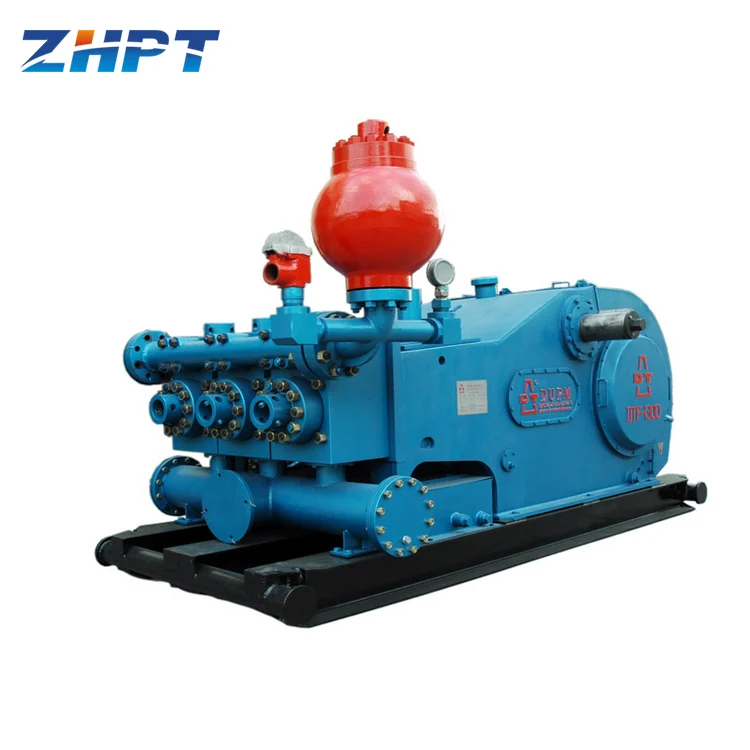
The 2,200-hp mud pump for offshore applications is a single-acting reciprocating triplex mud pump designed for high fluid flow rates, even at low operating speeds, and with a long stroke design. These features reduce the number of load reversals in critical components and increase the life of fluid end parts.
The pump’s critical components are strategically placed to make maintenance and inspection far easier and safer. The two-piece, quick-release piston rod lets you remove the piston without disturbing the liner, minimizing downtime when you’re replacing fluid parts.
Explore a wide variety of duplex mud pump on Alibaba.com and enjoy exquisite deals. The machines help maintain drilling mud circulation throughout the project. There are many models and brands available, each with outstanding value. These duplex mud pump are efficient, durable, and completely waterproof. They are designed to lift water and mud with efficiency without using much energy or taking a lot of space.
The primary advantage of these duplex mud pump is that they can raise water from greater depths. With the fast-changing technology, purchase machines that come with the best technology for optimum results. They should be well adapted to the overall configuration of the installation to perform various operations. Hence, quality products are needed for more efficiency and enjoyment of the machines" full life expectancy.
Alibaba.com offers a wide selection of products with innovative features. The products are designed for a wide range of flow rates that differ by brand. They provide cost-effective options catering to different consumer needs. When choosing the right duplex mud pump for the drilling project, consider factors such as size, shape, and machine cost. More powerful tools are needed when dealing with large projects such as agriculture or irrigation.
Alibaba.com provides a wide range of duplex mud pump to suit different tastes and budgets. The site has a large assortment of products from major suppliers on the market. The products are made of durable materials to avoid corrosion and premature wear during operations. The range of products and brands on the site assures quality and good value for money.
This website is using a security service to protect itself from online attacks. The action you just performed triggered the security solution. There are several actions that could trigger this block including submitting a certain word or phrase, a SQL command or malformed data.

This website is using a security service to protect itself from online attacks. The action you just performed triggered the security solution. There are several actions that could trigger this block including submitting a certain word or phrase, a SQL command or malformed data.

This website is using a security service to protect itself from online attacks. The action you just performed triggered the security solution. There are several actions that could trigger this block including submitting a certain word or phrase, a SQL command or malformed data.
Rig pump output, normally in volume per stroke, of mud pumps on the rig is one of important figures that we really need to know because we will use pump out put figures to calculate many parameters such as bottom up strokes, wash out depth, tracking drilling fluid, etc. In this post, you will learn how to calculate pump out put for triplex pump and duplex pump in bothOilfield and Metric Unit.
Bourgoyne, A.J.T., Chenevert , M.E. & Millheim, K.K., 1986. SPE Textbook Series, Volume 2: Applied Drilling Engineering, Society of Petroleum Engineers.

Choose a used Emsco FB-1600 Triplex Mud Pump from our inventory selection and save yourself some money on your next shallow drilling oilfield project. This Emsco FB-1600 Triplex Mud Pump is used and may show some minor wear.
We offer wholesale pricing on new Emsco FB-1600 Triplex Mud Pump and pass the savings on to you. Contact us to compare prices of different brands of Mud Pump. This equipment is brand new and has never been used.
Our large network often has surplus Emsco FB-1600 Triplex Mud Pump that go unused from a surplus purchase or a project that was not completed. Contact us to see what Emsco FB-1600 Triplex Mud Pump we have in inventory. The surplus Emsco FB-1600 Triplex Mud Pump are considered new but may have some weathering depending on where it was stored. Surplus oilfield equipment is usually stored at a yard or warehouse.
We have refurbished Mud Pumpthat have been used and brought up to functional standards. It is considered a ready to use, working Mud Pump. Please contact us for more information about our refurbished Emsco FB-1600 Triplex Mud Pump. These Mud Pump have been used and brought up to functional standards. It is considered a working Mud Pump. Please contact us for more information about the product.

When choosing a size and type of mud pump for your drilling project, there are several factors to consider. These would include not only cost and size of pump that best fits your drilling rig, but also the diameter, depth and hole conditions you are drilling through. I know that this sounds like a lot to consider, but if you are set up the right way before the job starts, you will thank me later.
Recommended practice is to maintain a minimum of 100 to 150 feet per minute of uphole velocity for drill cuttings. Larger diameter wells for irrigation, agriculture or municipalities may violate this rule, because it may not be economically feasible to pump this much mud for the job. Uphole velocity is determined by the flow rate of the mud system, diameter of the borehole and the diameter of the drill pipe. There are many tools, including handbooks, rule of thumb, slide rule calculators and now apps on your handheld device, to calculate velocity. It is always good to remember the time it takes to get the cuttings off the bottom of the well. If you are drilling at 200 feet, then a 100-foot-per-minute velocity means that it would take two minutes to get the cuttings out of the hole. This is always a good reminder of what you are drilling through and how long ago it was that you drilled it. Ground conditions and rock formations are ever changing as you go deeper. Wouldn’t it be nice if they all remained the same?
Centrifugal-style mud pumps are very popular in our industry due to their size and weight, as well as flow rate capacity for an affordable price. There are many models and brands out there, and most of them are very good value. How does a centrifugal mud pump work? The rotation of the impeller accelerates the fluid into the volute or diffuser chamber. The added energy from the acceleration increases the velocity and pressure of the fluid. These pumps are known to be very inefficient. This means that it takes more energy to increase the flow and pressure of the fluid when compared to a piston-style pump. However, you have a significant advantage in flow rates from a centrifugal pump versus a piston pump. If you are drilling deeper wells with heavier cuttings, you will be forced at some point to use a piston-style mud pump. They have much higher efficiencies in transferring the input energy into flow and pressure, therefore resulting in much higher pressure capabilities.
Piston-style mud pumps utilize a piston or plunger that travels back and forth in a chamber known as a cylinder. These pumps are also called “positive displacement” pumps because they literally push the fluid forward. This fluid builds up pressure and forces a spring-loaded valve to open and allow the fluid to escape into the discharge piping of the pump and then down the borehole. Since the expansion process is much smaller (almost insignificant) compared to a centrifugal pump, there is much lower energy loss. Plunger-style pumps can develop upwards of 15,000 psi for well treatments and hydraulic fracturing. Centrifugal pumps, in comparison, usually operate below 300 psi. If you are comparing most drilling pumps, centrifugal pumps operate from 60 to 125 psi and piston pumps operate around 150 to 300 psi. There are many exceptions and special applications for drilling, but these numbers should cover 80 percent of all equipment operating out there.
The restriction of putting a piston-style mud pump onto drilling rigs has always been the physical size and weight to provide adequate flow and pressure to your drilling fluid. Because of this, the industry needed a new solution to this age-old issue.
Enter Cory Miller of Centerline Manufacturing, who I recently recommended for recognition by the National Ground Water Association (NGWA) for significant contributions to the industry.
As the senior design engineer for Ingersoll-Rand’s Deephole Drilling Business Unit, I had the distinct pleasure of working with him and incorporating his Centerline Mud Pump into our drilling rig platforms.
In the late ’90s — and perhaps even earlier — Ingersoll-Rand had tried several times to develop a hydraulic-driven mud pump that would last an acceptable life- and duty-cycle for a well drilling contractor. With all of our resources and design wisdom, we were unable to solve this problem. Not only did Miller provide a solution, thus saving the size and weight of a typical gear-driven mud pump, he also provided a new offering — a mono-cylinder mud pump. This double-acting piston pump provided as much mud flow and pressure as a standard 5 X 6 duplex pump with incredible size and weight savings.
The true innovation was providing the well driller a solution for their mud pump requirements that was the right size and weight to integrate into both existing and new drilling rigs. Regardless of drill rig manufacturer and hydraulic system design, Centerline has provided a mud pump integration on hundreds of customer’s drilling rigs. Both mono-cylinder and duplex-cylinder pumps can fit nicely on the deck, across the frame or even be configured for under-deck mounting. This would not be possible with conventional mud pump designs.
Centerline stuck with their original design through all of the typical trials and tribulations that come with a new product integration. Over the course of the first several years, Miller found out that even the best of the highest quality hydraulic cylinders, valves and seals were not truly what they were represented to be. He then set off on an endeavor to bring everything in-house and began manufacturing all of his own components, including hydraulic valves. This gave him complete control over the quality of components that go into the finished product.
The second generation design for the Centerline Mud Pump is expected later this year, and I believe it will be a true game changer for this industry. It also will open up the application to many other industries that require a heavier-duty cycle for a piston pump application.

If you run a mud rig, you have probably figured out that the mud pump is the heart of the rig. Without it, drilling stops. Keeping your pump in good shape is key to productivity. There are some tricks I have learned over the years to keeping a pump running well.
First, you need a baseline to know how well your pump is doing. When it’s freshly rebuilt, it will be at the top efficiency. An easy way to establish this efficiency is to pump through an orifice at a known rate with a known fluid. When I rig up, I hook my water truck to my pump and pump through my mixing hopper at idle. My hopper has a ½-inch nozzle in it, so at idle I see about 80 psi on the pump when it’s fresh. Since I’m pumping clear water at a known rate, I do this on every job.
As time goes on and I drill more hole, and the pump wears, I start seeing a decrease in my initial pressure — 75, then 70, then 65, etc. This tells me I better order parts. Funny thing is, I don’t usually notice it when drilling. After all, I am running it a lot faster, and it’s hard to tell the difference in a few gallons a minute until it really goes south. This method has saved me quite a bit on parts over the years. When the swabs wear they start to leak. This bypass pushes mud around the swab, against the liners, greatly accelerating wear. By changing the swab at the first sign of bypass, I am able to get at least three sets of swabs before I have to change liners. This saves money.
Before I figured this out, I would sometimes have to run swabs to complete failure. (I was just a hand then, so it wasn’t my rig.) When I tore the pump down to put in swabs, lo-and-behold, the liners were cut so badly that they had to be changed too. That is false economy. Clean mud helps too. A desander will pay for itself in pump parts quicker than you think, and make a better hole to boot. Pump rods and packing last longer if they are washed and lubricated. In the oilfield, we use a petroleum-based lube, but that it not a good idea in the water well business. I generally use water and dish soap. Sometimes it tends to foam too much, so I add a few tablets of an over the counter, anti-gas product, like Di-Gel or Gas-Ex, to cut the foaming.
Maintenance on the gear end of your pump is important, too. Maintenance is WAY cheaper than repair. The first, and most important, thing is clean oil. On a duplex pump, there is a packing gland called an oil-stop on the gear end of the rod. This is often overlooked because the pump pumps just as well with a bad oil-stop. But as soon as the fluid end packing starts leaking, it pumps mud and abrasive sand into the gear end. This is a recipe for disaster. Eventually, all gear ends start knocking. The driller should notice this, and start planning. A lot of times, a driller will change the oil and go to a higher viscosity oil, thinking this will help cushion the knock. Wrong. Most smaller duplex pumps are splash lubricated. Thicker oil does not splash as well, and actually starves the bearings of lubrication and accelerates wear. I use 85W90 in my pumps. A thicker 90W140 weight wears them out a lot quicker. You can improve the “climbing” ability of the oil with an additive, like Lucas, if you want. That seems to help.
Outside the pump, but still an important part of the system, is the pop-off, or pressure relief valve. When you plug the bit, or your brother-in-law closes the discharge valve on a running pump, something has to give. Without a good, tested pop-off, the part that fails will be hard to fix, expensive and probably hurt somebody. Pop-off valve are easily overlooked. If you pump cement through your rig pump, it should be a standard part of the cleanup procedure. Remove the shear pin and wash through the valve. In the old days, these valves were made to use a common nail as the shear pin, but now nails come in so many grades that they are no longer a reliable tool. Rated shear pins are available for this. In no case should you ever run an Allen wrench! They are hardened steel and will hurt somebody or destroy your pump.
One last thing that helps pump maintenance is a good pulsation dampener. It should be close to the pump discharge, properly sized and drained after every job. Bet you never thought of that one. If your pump discharge goes straight to the standpipe, when you finish the job your standpipe is still full of fluid. Eventually the pulsation dampener will water-log and become useless. This is hard on the gear end of the pump. Open a valve that drains it at the end of every job. It’ll make your pump run smoother and longer.

This invention relates to apparatus useful in connection with the drilling of wells, such as oil wells, wherein a mud pump is used to circulate drilling mud under pressure through a drill string, down to and around the drill bit and out the annulus of the bore hole of the well to a mud reservoir; the apparatus of the present invention being useful for simultaneously degassing drilling mud and supercharging the mud pump.
In the drilling of deep wells, such as oil wells, it is common practice to penetrate the earth with a drill bit supported on a drill string in the bore of the well being drilled. In order to lubricate the drill bit, protect the well against blowouts, etc., it is conventional practice to circulate mud under pressure through the drill string down to and around the drill bit and up the annulus between the drill string and the bore of the well. Mud flowing from the well is passed through a suitable device such as a shaker, etc., in order to remove drill cuttings, etc., and is then delivered to a mud reservoir, such as a mud tank, for recirculation to the mud pump for pressured injection into the well.
It is also conventional practice to use a mud pump, such as a duplex or triplex mud pump comprising reciprocating pistons mounted in cylinders for pressuring the incoming drilling mud and delivering it to the well bore under pressure. The operation and construction of mud pumps is well known to those of ordinary skill in the art, as illustrated, for example, by the textbook "Mud Pump Handbook" by Samuel L. Collier (Gulf Publishing Company, Houston, Tex., 1983).
It is known, as explained in the Collier handbook, that the efficiency of a mud pump can be significantly improved by supercharging the pump; that is, by delivering drilling mud under pressure to the mud pump inlet to the cylinders containing the reciprocating pumping pistons.
It is also known to remove occluded gasses such as air, methane, etc., from drilling mud before it is delivered to the mud pump as illustrated, for example, by Burgess U.S. Pat. No. 3,973,930, Burgess U.S. Pat. No. 3,999,965 and Burgess U.S. Pat. No. 4,084,946.
Other drilling mud degassing devices are known to the art, such as those disclosed in Phillips et al. U.S. Pat. No. 4,088,457, Brown et al. U.S. Pat. No. 4,113,452, Egbert U.S. Pat. No. 4,365,977, Gowan et al. U.S. Pat. No. 4,397,659, etc.
Mud pumps used for delivering drilling mud under pressure to the bore hole of a well are conventionally of the type wherein a reciprocating piston in a cylinder is used to pressure drilling mud delivered to the cylinder for delivery to the well bore. Normally, two or three such cylinders are used, such pumps being conventionally referred to as duplex and triplex pumps. During each stroke of the piston, the piston is initially accelerated by an appropriate drive means, such as a crank shaft, from a starting position to a midcylinder position, and then decelerated to a final position within the cylinder. This constantly changing rate of motion of a reciprocating piston can result in knocking, cavitation, etc., all of which impair the efficiency of the pump. It is known to use centrifugal pumps, commonly known as superchargers, in order to deliver drilling mud to the inlet of the cylinder under pressure in order to alleviate such problems and improve the efficiency of operation of the pump.
It is undesirable to recirculate drilling mud containing occluded gases to a well bore, and therefore it is common practice to remove a significant portion of occluded gas from the drilling mud before it is recirculated to the mud pump. Normally, separate pieces of equipment that operate independently of each other are used for supercharging the mud pump and for degassing the drilling mud.
It has been discovered in accordance with the present invention that a drilling mud degasser of the type disclosed in the Burgess patents can be modified to simultaneously degas drilling mud and to supercharge the mud pump to which the degassed mud is to be delivered.
This is accomplished in accordance with the present invention through the provision of a device for simultaneously supercharging a mud pump having pistons reciprocably mounted in cylinders while degassing drilling mud to be delivered to said pistons comprising:
vacuum chamber means for continuously accelerating and centrifuging drilling mud under vacuum to thereby substantially completely remove occluded gas from the drilling mud,
a first conduit interconnecting said vacuum chamber with a drilling mud reservoir for delivering drilling mud to be degassed to said vacuum chamber means,
a first valve controlled branch conduit interconnecting said second conduit with said drilling mud reservoir for delivering drilling mud to said drilling mud reservoir when the pressure in said second conduit exceeds a predetermined value, and
a second branch conduit containing normally closed flow control means interconnecting said second conduit with said first conduit and said drilling mud reservoir operable on loss of pressure in said second conduit to permit flow of drilling mud directly from said drilling mud reservoir to said second conduit.
Referring now to the drawing, there is shown a supercharging drilling mud degasser 10 of the present invention which comprises a degassing chamber designated generally by the number 12, a power source such as an electric powered motor or a hydraulically powered motor designated generally by the number 14, a vacuum blower such as a regenerative vacuum blower, designated generally by the number 16, a gear box designated generally by the number 18, an evacuation pump designated generally by the number 20 and a drilling mud chamber designated generally by the number 22.
In accordance with this construction, there is provided a drilling mud degasser of the type shown in Burgess U.S. Pat. No. 4,084,946, housed in a cylindrical pressure vessel 24. The motor 14 is supported on vacuum blower 16 which, in turn, is supported by vacuum motor support 26 and vacuum blower brackets 28. To facilitate movement of the degasser 10, motor handling brackets 30 may be provided on the top of the motor 14 to which the hook of a crane or other appropriate means (not shown) may be attached.
A foam separation impeller 36 is rotatably secured to a gear shaft 38 depending from and operatively connecting the gear box 18, the gear shaft 38 being also operatively rotatably secured to the top of a rotating slotted centrifuge tube 40. With this construction, the vacuum blower 16 can be operated at an appropriate speed necessary for the generation of a vacuum of from about 10 to 15 inches of mercury while the foam separator impeller 36 and the slotted centrifuge tube 40 may be rotated at a different and more appropriate slower rate.
Drilling mud pump impeller 42 is fixed to the centrifuge tube 40 for rotation therewith within the housing 46 of drilling mud evacuation pump 20. Cross braces 48 mounted in the cylindrical vessel 24 support lower stops 50 and upper stops 52 for an annular float 56 that surrounds the slots of the centrifuge tube 40 and partially closes them, such that the free area of the slots will be determined by the relative position of the annular float 56.
A drilling mud inlet 60 is connected to the bottom of the housing 46 for the evacuation pump 20 for the delivery of degassed drilling mud thereto. Drilling mud is delivered to the slotted centrifuge tube 40 by an inlet conduit 62 which preferably terminates inside the housing 46 for the evacuation pump 20. The top of the inlet line 62 is spaced from the bottom of the slotted centrifuge tube 40 so that the rotating centrifuge tube 40 can rotate freely without bearing upon the top of the inlet line 62. The resultant "controlled seepage" of fluid from the inlet tube 62 into the evacuation pump 20 provides a low pressure area for high effeciency scanvenging of occluded gases. Also, there is no need for bearings and seals at the bottom of the slotted centrifuge tube 40.
With this construction there is also provided an outlet line or conduit 66 connected with the discharge side of the evacuation pump 20 and extending through the wall of the cylinder 24 for connection with a suitable first conduit 68 leading, for example, to a triplex pump 70 for injecting drilling mud under pressure into a well penetrating a subterranean formation in order to lubricate the drill bit, protect the well against blow outs, etc., it is conventional practice to circulate mud under pressure through the drill string down to and around the drill bit and up the annulus beteen the drill string and the bore of the well. Mud flowing from the well is passed through a suitable device such as a shaker, etc. (not shown) in order to remove drill cuttings, etc., and is then delivered to a mud reservoir, such as a mud tank 84, for recirculation to the mud pump 70 in the manner described herein for pressured injection into the well.
The first conduit 68 may comprise, for example, a connecting pipe 72 interconnecting the outlet line 66 with the flexible hose 74 which, in turn, is connected to a mud pump inlet line 76. The flexible hose 74, which is provided for ease in alignment, may be secured to the connecting pipe 72 by a clamp 78 of any suitable construction and to the mud pump inlet line 76 by a clamp 80 of any suitable construction.
A second conduit 82 interconnects a drilling mud reservoir such as a mud tank 84 with the inlet conduit 62 leading to the slotted centrifuge tube 40 for the degasser 10.
Preferably, the second conduit 82 is provided with valve means such as a butterfly valve 86 which may be used to close the second conduit 82 when both the drilling mud degasser 10 and the mud pump 70 are to be idled for any appreciable time.
A first branch conduit 88 interconnects the first conduit 68 with the mud tank 84 and contains pressure sensitive control means such as a spring biased relief valve 90 in order to permit drilling mud to recycle from the first conduit 68 to the mud tank 84 when the pressure in the first conduit 68 exceeds a predetermined value.
A second branch conduit 92 interconnects the first conduit 68 with the inlet conduit 62 and the second conduit 82. The second branch conduit 92 contains normally closed flow control means such as a check valve 94 to permit flow of drilling mud directly from the mud tank 84 to the mud pump 70 if the pressure in the first conduit 68 falls below a predetermined value.
During drilling operations, rotation of an appropriate vacuum blower such as a regenerative vacuum blower by the drive shaft 32 for the motor 14 will generate a vacuum in the degassing chamber 12 such that drilling mud sprayed from the slots in the centrifuge tube 40 will tend to impact upon the inner sides of the degassing chamber 12 thereby initiating degassing of the drilling mud fed through the inlet line 62. Rotation of the centrifuge tube 40 will impart upward accelerating rotary motion to partially degassed drilling mud delivered thereto through the line 62 and the resultant spraying of the thus centrifuged drilling mud through the slots in the centrifuge tube 40 will result in a sheet of drilling mud being sprayed onto and impacting on the inner walls of the degassing chamber 12 to thus substantially complete the removal of gas from the drilling mud. The thus degassed drilling mud will flow downwardly past cross braces 48 and into inlet 60 leading through the housing 46 of the evacuation pump 20 where the impeller 42 will repressure the now degassed drilling mud for discharge through the outlet line 66 which is interconnected with a triplex pump 70 by first conduit 68 for supercharging the pump 70, which further pressures the degassed drilling mud for injection into a well bore penetrating a subterranean formation.
In order to prevent the entrainment of drilling mud droplets in the gases withdrawn through the gas evacuation suction pipe 98, a splatter plate 100 is provided in the degassing chamber 12 and a combination of a foam separation impeller 36 with a splatter disk 102 is provided adjacent the top of the degassing chamber 12 so that gas liberated in the vacuum chamber must follow a sinuous path arriving at the upper chamber gas evacuation suction pipe 98.
In accordance with the present invention, the motor 14 is operated such that drilling mud delivered to the first conduit 68 will be at a predetermined appropriate supercharging pressure for the mud pump 70, (e.g. a pressure of about 20 to 30 psig).
The pressure sensitive control means, such as a spring biased relief valve 90, is set to open at a predetermined pressure about 5 to 10 psi higher than the desired pressure in the first conduit 68 so that, if the indicated pressure limit is exceeded, the pressure relief valve 90 will open in order to permit drilling mud to recycle to the mud tank 84.
This will happen if the mud pump 70 malfunctions and also when the mud pump 70 is turned off, as will happen from time to time. For example, it is necessary to turn off the mud pump 70 during drilling operations when a new stand of drill pipe is to be added to the drill string. It is also necessary to turn off the mud pump 70 when the drill string is being withdrawn from the well bore in order to replace the drill bit, while well logging operations are in progress, if it is necessary to "fish" for a piece of equipment lost down the hole, etc. However, if the drilling mud in the mud tank 84 is permitted to remain quiescent for more than a limited period of time, the drilling mud may start to gel and/or to stratify. This problem is conventionally avoided by providing a separate agitator (not shown) for the mud tank 84 in order to stir the drilling mud when the mud pump 70 is idle. However, through the provision of the present invention, there is no need for a separate agitator for the mud tank 84 because recirculation of drilling mud through the first branch conduit 88 will impart a "roiling" motion or agitation to the drilling mud in mud tank 84 to inhibit gelling and/or stratification of the drilling mud while the mud pump 70 is idle.
Loss of pressure in the first conduit 68 can occur in the event of malfunction of the degasser 10 or in the event it is desired to shut the degasser 10 down for a limited period of time. In this event, drilling mud flows directly from the mud tank 84 through the second conduit 82, the second branch conduit 92 and the flexible hose 74 to the mud pump 70 so that the mud pum 70 is not "starved" for drilling mud to be injected into the well.

Mud pumps are the pumps deployed in the oil and gas industry, mainly to circulate drilling fluids and other kinds of fluids in and out of the drilled wells for exploration. The mud pumps transfer the fluids at a very high pressure inside the well using the piston arrangement. The number of pistons decides the displacement and efficiency of working of the mud pumps, originally only dual piston pumps and three-piston pumps were used, but the technological advancements have seen pumps with five and six pistons to come up. Currently the triplex pumps which have three pistons are used, but the duplex pumps having two pumps are still deployed in the developing countries.
Based on its types, global mud pump market can be segmented into duplex, triplex, and others. The triplex mud pumps will dominate the mud pump marking in the given forecast period owing to its advantages and ongoing replacement of duplex pumps with triplex pumps. Based on operation, the global mud pumps market can be segmented into electric and fuel engine.
The electric mud pumps will dominate the market during the given forecast period due to the advantage of eliminating the harmful carbon emission which is done in the case of fuel engine pumps. Based on its application, the global mud pumps market can be segmented into oil & gas, mining, construction, and others.
The major market driver for the global mud pumps market is the increasing exploration activities taking place in various regions of the world to satisfy the increased energy demand. The number of drilled wells has increased in recent years, which has certainly impacted the growth of the mud pumps market in both oil & gas and mining sectors.
Key market restraint for the global mud pumps market is the drift towards the cleaner sources of energy to reduce the carbon emissions, which will certainly decrease the demand for oil & gas and therefore will have a negative impact on the growth of the global mud pumps market.
Some of the notable companies in the global mud pump market are Mud King Products, Inc. Gardner Denver Pumps, Weatherford, Schlumberger, National Oilwell Varco, China National Petroleum Corporation, Flowserve Corporation, MHWirth, American Block, Herrenknecht Vertical Gmbh, Bentec GmbH Drilling & Oilfield Systems, Drillmec Inc, Sun Machinery Company, Shale Pumps, and Dhiraj Rigs.
The global mud pump market has been segmented into North America, Europe, Asia Pacific, Latin America, and Middle East & Africa. Owing to the well-established production sector and stable exploration industry North America holds the largest market for the mud pumps. The onshore exploration activities of oil & gas have increased at a good rate in the North America region, which has certainly boosted the growth of the mud pumps market in the region.
The demand from Europe and Asia Pacific has also increased due to exploration activities in both the regions owing to the increased energy demand. The energy demand specifically in the Asia Pacific has increased due to the increased population and urbanization. The Middle East and Africa also hold significant opportunities for the mud pumps market with increased exploration activities in the given forecast period.
In August 2018, Henderson which is a leading company in sales and service of drilling rigs, and capital drilling equipment in Texas signed a contract with Energy Drilling Company for the purchase and upgrade of oil field equipment’s which included three 1600hp × 7500psi mud pumps. This will be the first refurbishment completed at Henderson’s new service center and rig yard.
In January 2018, Koltek Energy Services launched the 99-acre facility for the testing of the oil field equipment in Oklahoma. This will allow the oil field equipment manufacturers to test their equipment at any given time. The company has deployed the MZ-9 pump which has a power rating of 1000Hp.


 8613371530291