
duplex mud pump formula price
Rig pump output, normally in volume per stroke, of mud pumps on the rig is one of important figures that we really need to know because we will use pump out put figures to calculate many parameters such as bottom up strokes, wash out depth, tracking drilling fluid, etc. In this post, you will learn how to calculate pump out put for triplex pump and duplex pump in bothOilfield and Metric Unit.

Pump Output per Stroke (PO): The calculator returns the pump output per stroke in barrels (bbl). However this can be automatically converted to other volume units (e.g. gallons or liters) via the pull-down menu.
A triplex mud (or slush) pump has three horizontal plungers (cylinders) driven off of one crankshaft. Triplex mud pumps are often used for oil drilling.

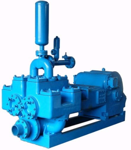
A mud pump is a reciprocating piston/plunger pump designed to circulate drilling fluid under high pressure (up to 7,500 psi (52,000 kPa)) down the drill string and back up the annulus. A duplex mud pump is an important part of the equipment used for oil well drilling.
Duplex mud pumps (two piston/plungers) have generally been replaced by the triplex pump, but are still common in developing countries. Two later developments are the hex pump with six vertical pistons/plungers, and various quintuplex’s with five horizontal piston/plungers. The advantages that Duplex mud pumps have over convention triplex pumps is a lower mud noise which assists with better Measurement while drilling and Logging while drilling decoding.
Use duplex mud pumps to make sure that the circulation of the mud being drilled or the supply of liquid reaches the bottom of the well from the mud cleaning system. Despite being older technology than the triplex mud pump, the duplex mud pumps can use either electricity or diesel, and maintenance is easy due to their binocular floating seals and safety valves.
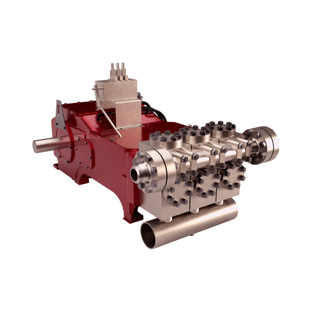
A mud pump is composed of many parts including mud pump liner, mud pump piston, modules, hydraulic seat pullers, and other parts. Parts of a mud pump:housing itself
Duplex pumps are used to provide a secondary means of fuel transfer in the event of a failure of the primary pump. Each pump in a duplex set is sized to meet the full flow requirements of the system. Pump controllers can be set for any of the following common operating modes:Lead / Lag (Primary / Secondary): The lead (primary) pump is selected by the user and the lag (secondary pump operates when a failure of the primary pump is detected.
Alternating: Operates per Lead / Lag (Primary / Secondary) except that the operating pump and lead / lag status alternate on consecutive starts. A variation is to alternate the pumps based on the operating time (hour meter) of the lead pump.

One of the most popular triplex pumps in the market, the TEE is perfect for Hot Oil, and Well-Kill applications. The GD Energy Products TEE offers tremendous versatility, available with pistons & liners, or plungers & packing, in multiple sizes, an optional gear reducer, and drive capability from either side. A cast frame and dual crosshead lubrication help ensure the longest possible life even in the toughest conditions.
Duplex Pumps - Used Emsco D-500 16" stroke, 500hp duplex pump only. 268 gpm @ 2720 psi @ 65rpm with 4 3/4" pistons. 751 gpm @ 970 psi @ 65 rpm with 7 1/2" Pistons More Info
Duplex Pumps - Used 3 1/2" - 5" x 10" stroke duplex pump,96 HP, 83 GPM @ 1500 PSI @ 85 RPM with 3 1/2" Pistons or 182 GPM @ 772 PSI @ 85 RPM with 5" pistons. More Info

This approach works well but relying on a printed reference is not without the risk since the wrong value can still be selected from the fine print of a reference table, or the reference document can be damaged or lost (e.g., dropped in the mud pit) altogether.
So, let’s address the alternative approach of using simple mathematical formulas to determine the same information. Although the reliance on a single sheet of paper to obtain the needed value is avoided with this approach, the potential for human error or miscalculation remains, meaning regardless of the approach, great care in determining such values is prudent.
Once we have obtained the number of units we need, we can convert that value into a familiar unit that we’re comfortable working with. For example, we may use a formula to determine the volume of a borehole to be 100 cubic feet (ft3), but we want to know the answer in gallons. Since we know that every cubic foot contains 7.48 gallons, we can easily convert that borehole volume to 748 gallons.
We want to know the volume of material (filter pack sand, cement grout, etc.) that is to be placed in the annulus to assure the annular void has been properly and completely filled (Figure 1). The conceptual diagram showing the variables used for calculating an annular void is shown in Figure 2, and the formula for the annular volume calculation is:
In this calculation, the “d” value is the diameter of the casing or pipe diameter, and the “D” value is the borehole diameter (Figure 2). The sump area below the base of the casing has only one diameter in the open borehole, so the “d” value is omitted, and the formula just becomes:
If excessive hydraulic pressures are exerted on a well casing, it will collapse. We generally know the collapse strength of the well casing from the casing supplier or from standard references such as the charts in American Water Works Association Standard A100. The hydraulic pressures applied to the outside of the well casing depend on the density of the liquid and the depth of submergence (Figure 1). Applying the fluid density (measured in the field) and depth (Figure 2), the formula for hydraulic pressure head calculation is:
The hydraulic head formula is applicable to the hydraulic pressure head for any liquid, but we most commonly use this calculation during cement seal installation, since cement grout is generally the heaviest liquid being introduced to the annulus during well construction.
The intermediate casing can be sealed using the pressure grouting technique (Figure 3) to pump cement slurry down through the drill pipe and out to the annulus through a float shoe (a drillable check valve connected to the base of the casing). The inside of the intermediate casing is kept full of water during the cement placement to equilibrate hydraulic pressures inside and outside the casing. After the intermediate casing is sealed with the pressure grouted cement, the float shoe can be drilled out and the borehole advanced for installation of the screen and filter pack in the lower part of the well.
The buoyancy calculation is more of a conceptual comparison than a pure mathematical formula. This analysis involves some visualization be made on the part of the groundwater professional.
The pounds per linear foot of any casing or screen material is generally provided by the casing or screen supplier, but the variables in Figure 2 can be applied to the following formula to estimate the casing string weight:
This string weight formula is applicable to blank casing only, and material suppliers should be consulted for detailed pounds per linear foot values and safe hang weights for well screens. This formula is broadly applicable, however, and handy for a quick double check on material weights.
There are several calculations that are commonly applied by drilling fluid engineers (mud engineers) to determine the time period required for the fluid to move from one location in the borehole to another. Some of the more common equations are described below.
The uphole velocity calculation provides a determination of the speed at which the drilling mud will flow as it moves up the borehole. For direct air rotary or reverse circulation drilling methods, the uphole velocity is high, so this calculation is generally applicable only for the direct mud-rotary drilling method. The formula for uphole velocity is:
Notice the uphole velocity formula is similar to the annular volume formula in that both those calculations use the factor (D2 – d2) to address the cross-sectional area of the annulus. However, the constants in these two formulas are different (0.005454 versus 24.51), which can be confusing. Keep in mind, however, that the constants primarily just provide unit conversions.
If we do the same thing by first calculating the annular volume and then applying the 10 gpm flow rate to it, we will get an identical result of 3.83 ft/minute. The uphole velocity formula provides a more direct method to determine uphole velocity, whereas the annular volume formula provides a more direct method to calculate the annular volume.
We can calculate the bottoms-up time by using the uphole velocity formula with the borehole depth and drilling mud flow rate plugged in, but that flow rate is being generated by the mud pump, and positive displacement mud pumps (duplex or triplex) are almost never equipped with a flow meter. To determine the flow coming from the mud pump, we can use the formulas:
Remember the strokes are counted in both the forward and backward directions on a duplex pump, but only in the forward direction on a triplex pump. Drillers often have reference charts that provide oilfield barrels per stroke (bbl/stroke), which can be converted to gpm by timing the strokes per minute and converting barrels to gallons (1 barrel = 42 gallons).
A specified volume of drilling fluids (called a pill) can be circulated to a particular depth interval within the borehole (called spotting), so that the additives in the pill of drilling mud can address the borehole problem at a particular depth of the borehole. This is shown in Figure 6(C).
The calculation for time required to spot a pill of drillingfluid involves determining the pumping time (at the calculated flow rate) required to displace the fluid so that the drilling mud additives are located adjacent to the problematic interval. This approach is used by mud engineers to address problems such as lost circulation or stuck drill pipe.
The formulas and calculations provided in this column and elsewhere provide important tools for us to quantify the variables we need for water well design and construction. However, it is important to remember that “doing the math” is not a replacement for applying professional knowledge and consideration to determine whether the mathematical result makes common sense.

This article will focus on understanding of MWD signal decoding which is transmitted via mud pulse telemetry since this method of transmission is the most widely used commercially in the world.
As a basic idea, one must know that transmitted MWD signal is a wave that travels through a medium. In this case, the medium is mud column inside the drill string to mud pumps. Decoding is about detecting the travelling wave and convert it into data stream to be presented as numerical or graphical display.
The signal is produced by downhole transmitter in the form of positive pulse or negative pulse. It travels up hole through mud channel and received on the surface by pressure sensor. From this sensor, electrical signal is passed to surface computer via electrical cable.
Noise sources are bit, drill string vibration, bottom hole assemblies, signal reflection and mud pumps. Other than the noises, the signal is also dampened by the mud which make the signal becomes weak at the time it reaches the pressure sensor. Depth also weaken the signal strength, the deeper the depth, the weaker the signal detected.
Rock bit may create tri-lobe pattern. This pattern is created by the cones of the bit on the bottom of the hole. While drilling, the bit’s cones ride along this tri-lobe pattern and makes the bit bounce or known as axial vibration. As the bit bounces, back pressure is produced at the bit nozzles and transmitted to surface. The frequency of the noise created by bit bounce correlates with bit RPM. The formula to calculate its frequency is 3*(bit RPM)/60. When the bit bounce frequency match with MWD signal frequency, decoding is affected.
BHA components that have moving mechanical parts such as positive mud motor and agitator create noise at certain frequency. The frequency produced by these assemblies depends on the flow rate and the lobe configuration. The higher the flow rate and the higher the lobe configuration creates higher noise frequency.
Thruster, normally made up above MWD tool, tends to dampen the MWD signal significantly. It has a nozzle to use mud hydraulic power to push its spline mandrel – and then push the BHA components beneath it including the bit – against bottom of the hole. When the MWD signal is passing through the nozzle, the signal loses some of its energy. Weaker signal will then be detected on surface.
The common sources of signal reflection are pipe bending, change in pipe inner diameter or closed valve. These are easily found in pipe manifold on the rig floor. To avoid the signal reflection problem, the pressure sensor must be mounted in a free reflection source area, for example close to mud pumps. The most effective way to solve this problem is using dual pressure sensors method.
Mud pump is positive displacement pump. It uses pistons in triplex or duplex configuration. As the piston pushes the mud out of pump, pressure spikes created. When the piston retracts, the pressure back to idle. The back and forth action of pistons produce pressure fluctuation at the pump outlet.
Pressure fluctuation is dampened by a dampener which is located at the pump outlet. It is a big rounded metal filled with nitrogen gas and separated by a membrane from the mud output. When the piston pushes the mud the nitrogen gas in the dampener will be compressed storing the pressure energy; and when the piston retracts the compressed nitrogen gas in the dampener release the stored energy. So that the output pressure will be stable – no pressure fluctuation.
The dampener needs to be charged by adding nitrogen gas to certain pressure. If the nitrogen pressure is not at the right pressure, either too high or too low, the pump output pressure fluctuation will not be stabilized. This pressure fluctuation may match the MWD frequency signal and hence it disturbs decoding, it is called pump noise.
When the pump noise occurs, one may simply change the flow rate (stroke rate) so that the pump noise frequency fall outside the MWD frequency band – and then apply band pass frequency to the decoder.
The formula to calculate pump noise frequency is 3*(pump stroke rate)/60 for triplex pump and 2*(pump stroke rate)/60 for duplex pump. The rule of thumb to set up dampener pressure charge is a third (1/3) of the working standpipe pressure.
Sometime the MWD signal is not detected at all when making surface test although the MWD tool is working perfectly. This happen whenever the stand pipe pressure is the same with the pump dampener pressure. Reducing or increasing test flow rate to reduce or increase stand pipe pressure helps to overcome the problem.
When the MWD signal wave travels through mud as the transmission medium, the wave loses its energy. In other words, the wave is giving some energy to the mud.
The mud properties that are affecting MWD signal transmission is viscosity and weight. The increasing mud weight means there is more solid material or heavier material in the mud. Sometimes the mud weight increment is directly affecting mud viscosity to become higher. The MWD signal wave interacts with those materials and thus its energy is reduced on its way to surface. The more viscous the mud and the heavier the mud, the weaker the signal detected on surface.
Aerated mud often used in underbalance drilling to keep mud influx into the formation as low as possible. The gas injected into the mud acts as signal dampener as gas bubble is compressible. MWD signal suffers severely in this type of mud.
Proper planning before setting the MWD pulser gap, flow rate and pump dampener pressure based on mud properties information is the key to overcome weak signal.
The further the signal travels, the weaker the signal detected on the surface. The amount of detected signal weakness ratio compare to the original signal strength when it is created at the pulser depends on many factors, for example, mud properties, BHA component, temperature and surface equipment settings.

When two (or more) pumps are arranged in serial their resulting pump performance curve is obtained by adding theirheads at the same flow rate as indicated in the figure below.
Centrifugal pumps in series are used to overcome larger system head loss than one pump can handle alone. for two identical pumps in series the head will be twice the head of a single pump at the same flow rate - as indicated with point 2.
With a constant flowrate the combined head moves from 1 to 2 - BUTin practice the combined head and flow rate moves along the system curve to point 3. point 3 is where the system operates with both pumps running
When two or more pumps are arranged in parallel their resulting performance curve is obtained by adding the pumps flow rates at the same head as indicated in the figure below.
Centrifugal pumps in parallel are used to overcome larger volume flows than one pump can handle alone. for two identical pumps in parallel and the head kept constant - the flow rate doubles compared to a single pump as indicated with point 2
Note! In practice the combined head and volume flow moves along the system curve as indicated from 1 to 3. point 3 is where the system operates with both pumps running
In practice, if one of the pumps in parallel or series stops, the operation point moves along the system resistance curve from point 3 to point 1 - the head and flow rate are decreased.


 8613371530291