failing mud pump factory

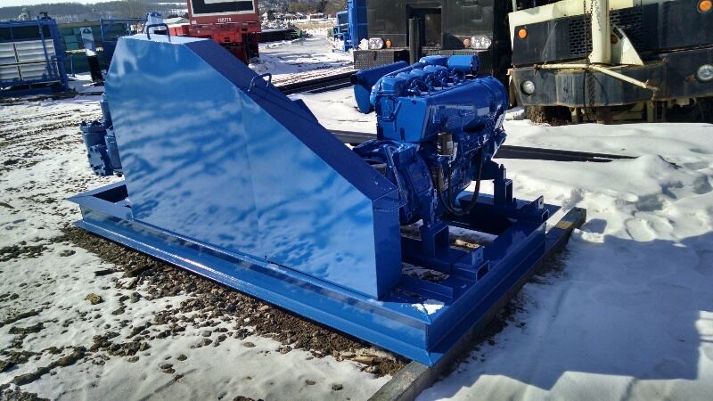
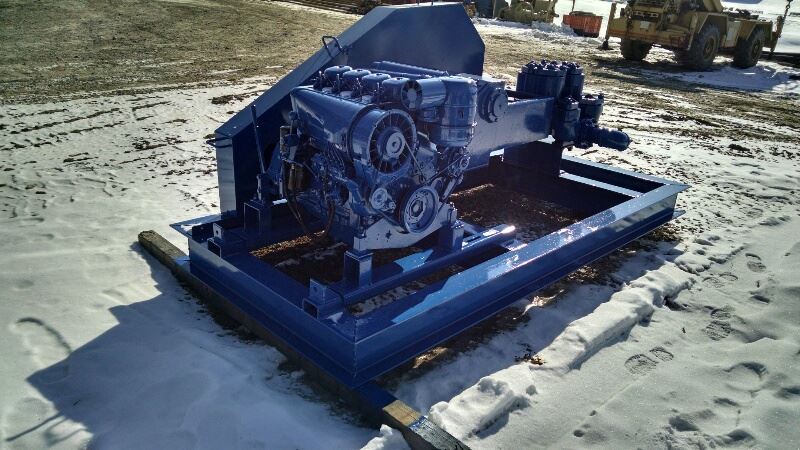
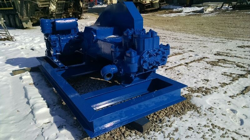
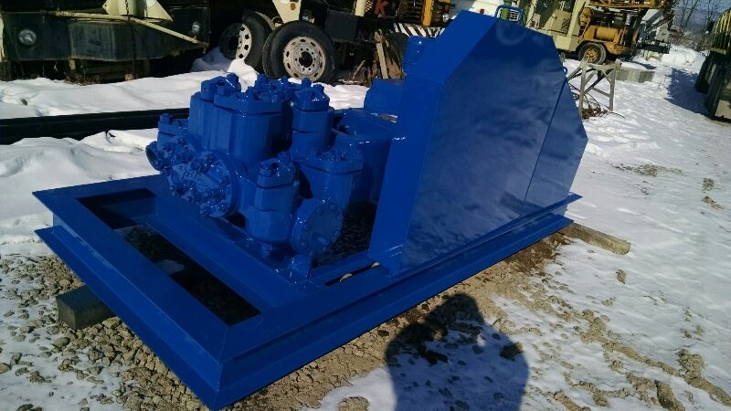
Mud pump is the key equipment in drilling operation. If mud is compared to blood in drilling operation, mud pump is the heart of blood supply in drilling production. Therefore, its importance in drilling production is self-evident, and the spare parts of mud pump play a certain role in this.
Mud pump is a kind of machine which can transport mud or water to drill hole in the process of drilling. It is an important part of drilling equipment. Its main function is to inject mud into the well with the bit, cool the bit, clean the drilling tool, stabilize the well wall, drive the drilling, and bring the cuttings back to the ground after drilling.
In the normal circulation drilling, the mud pump is to send the surface flushing medium - clear water, mud or polymer flushing liquid under a certain pressure through the high-pressure hose, faucet and the center hole of drill string directly to the bottom of the drill bit, so as to cool the drill bit, remove the cuttings and transport them to the surface. The mud pump is driven by the power machine to rotate the crankshaft of the pump. The crankshaft drives the piston to do reciprocating motion in the pump cylinder through the crosshead. Under the alternating action of the suction and discharge valves, the purpose of pressing and circulating the flushing fluid is realized. Different types of mud pumps are used in different cases to ensure the smooth proceeding of the drilling operation.
According to the use of the mud pump, the leakage of the valve box, the burning of the bearing and the abnormal noise are all frequent faults that affect the normal use of the mud pump. Therefore, careful study of the causes of the problem plays a key role in prolonging the service life of the mud pump. At this time, a certain amount of spare parts of the mud pump are needed.
In the process of using the mud pump, the equipment failures caused by specific reasons are different. Reasonable use and maintenance of the equipment can extend the service life of the equipment. At the same time, in strict accordance with the basic elements of normal operation of the drilling pump, "medium power, medium pump pressure, medium speed operation, tight, tight, leak tight, pump pressure does not fluctuate, temperature is normal, sound is normal", the operation can ensure the good operation of the equipment. Of course, it"s also important to find the right mud pump spare parts!

The fluid end of a duplex or triplex pump offers hundreds of opportunities for error. The results of an error in such a high-pressure system can mean (1) expensive downtime on the pump and maybe the entire rig, (2) expensive repair-replacement, and (3) possible injury or death of a crewman or a company man. Under the laws of nature, pump pistons and liners will wear, and there will be some corrosion and metallurgical imperfections, but the majority of pump failures are manmade. Theoretically, thorough training and retraining should avoid most mud pump problems. Realistically, a critical failure analysis during repair will be necessary to determine how to correct the failure. Telltale signs of trouble are distortion of piston rods, frayed piston polymer, discoloration, odor, hard-to-remove piston, rod cracks, pitting, total fracture, valve seat wear, and unsuitable external appearance.

(1) The diesel engine speed of the main pump station is too low, the fuel supply is insufficient, and the supply pressure of the hydraulic system is too low;
(2) The hydraulic system of the mud pump supplied by the main pumping station is faulty or the pressure adjustment of the overflow valve in the system is low and the internal leakage is serious, and the supply pressure is insufficient;
(1) Increase the speed of the diesel engine at the main pump station (n is greater than or equal to 1500 r/min), increase the fuel supply of the motor, and increase the effective working pressure of the hydraulic system (above 10MPa);
(1) Reason analysis: The diesel engine speed of the main pumping station is low and the fuel supply is insufficient, resulting in insufficient flow of the water pump and the pressure cannot rise.
(2) Solution: Increase the diesel engine speed of the main pump station (n is greater than or equal to 1500 r/min), increase the motor oil supply, increase the water pump flow, and then increase the pressure; unscrew the pressure gauge and fill the buffer with oil or After replacing the rubber diaphragm, fill it with engine oil.
The reasons and solutions for the failures that often occur in mud pump operations are listed above. The equipment failures caused by specific reasons in the use of mud pumps are different. Reasonable use and maintenance of the equipment can extend the service life of the equipment.

Mud Pumps are generally used in rural areas as river mud, manure, river water, slurry feed, suction and irrigation, instead of shouldering human burdens, and used for drainage and drought resistance. It can also be used for car front, river mud, and fertilizer production. It can also be used as a simple mobile fire-fighting pump in rural areas, and can also be used for fish farming to bring water to clear ponds and fish ponds to increase oxygen. It can also be used in municipal, chemical, printing and dyeing, medicine, shipbuilding, foundry, food and other industries to suck thick liquid, dirty liquid, paste, quicksand and flowing sludge from urban rivers, etc. It can be used as a coal mine to remove small gravels containing mud Fluid. If it is combined with a high-pressure water pump and a water gun to form a hydraulic mechanized earthwork unit, it can be used for excavation and transportation of land leveling, river courses, ponds, air defense, and underground projects.
Reasons: insufficient filling and diversion of water, inability to discharge the air in the pump, air leakage in the suction pipe, large clearance between the front liner and the impeller
Reason: there is air in the Pump, the gap between the impeller and the front liner is large, the clutch is not closed tightly, the impeller or the liner is worn

I’ve run into several instances of insufficient suction stabilization on rigs where a “standpipe” is installed off the suction manifold. The thought behind this design was to create a gas-over-fluid column for the reciprocating pump and eliminate cavitation.
When the standpipe is installed on the suction manifold’s deadhead side, there’s little opportunity to get fluid into all the cylinders to prevent cavitation. Also, the reciprocating pump and charge pump are not isolated.
The suction stabilizer’s compressible feature is designed to absorb the negative energies and promote smooth fluid flow. As a result, pump isolation is achieved between the charge pump and the reciprocating pump.
The isolation eliminates pump chatter, and because the reciprocating pump’s negative energies never reach the charge pump, the pump’s expendable life is extended.
Investing in suction stabilizers will ensure your pumps operate consistently and efficiently. They can also prevent most challenges related to pressure surges or pulsations in the most difficult piping environments.

The article presents selected technical issues relating to drilling performed by a drillship, one type of drilling rigs. Basic problems encountered in the main function of such rigs − drilling a well − are failures of mud pumps. The authors investigate these pumps in operational conditions, aiming at development of a system for monitoring the technical condition of these pumps. Work on a diagnostic system is in progress that will permit to predict the condition of mud pump valves well in…Expand

Continental Emsco Drilling Products, Inc., which consisted of Emsco drilling machinery and Wilson mobile rigs, was purchased by National-Oilwell, Inc on July 7, 1999. To our knowledge, no pumps have been manufactured and sold under the Emsco brand name since National-Oilwell acquired them.
Fairbanks Morse pumps are currently manufactured in Kansas City, Kansas. Fairbanks Morse is a division of Pentair ever since August, 1997 when Pentair purchased the General Signal Pump Group.
Gaso pumps are manufactured by National Oilwell Varco. Gaso was acquired as "Wheatley Gaso" by National-Oilwell in the year 2000. At the time, Wheatley Gaso was owned by Halliburton.
Skytop Brewster pumps are no longer available as new pumps. Skytop Brewster(Cnsld Gold), a unit of Hansen PLC"s Consolidated Gold Fields subsidiary, was acquired while in bankruptcy by National-Oilwell, Inc. in November, 1999.

Mud Pumps are generally used in rural areas as river mud, manure, river water, slurry feed, suction and irrigation, instead of shouldering human burdens, and used for drainage and drought resistance. It can also be used for car front, river mud, and fertilizer production. It can also be used as a simple mobile fire-fighting pump in rural areas, and can also be used for fish farming to bring water to clear ponds and fish ponds to increase oxygen. It can also be used in municipal, chemical, printing and dyeing, medicine, shipbuilding, foundry, food and other industries to suck thick liquid, dirty liquid, paste, quicksand and flowing sludge from urban rivers, etc. It can be used as a coal mine to remove small gravels containing mud Fluid. If it is combined with a high-pressure water pump and a water gun to form a hydraulic mechanized earthwork unit, it can be used for excavation and transportation of land leveling, river courses, ponds, air defense, and underground projects.
Reasons: insufficient filling and diversion of water, inability to discharge the air in the pump, air leakage in the suction pipe, large clearance between the front liner and the impeller
Reason: there is air in the Pump, the gap between the impeller and the front liner is large, the clutch is not closed tightly, the impeller or the liner is worn

The mud pump piston is a key part for providing mud circulation, but its sealing performance often fails under complex working conditions, which shorten its service life. Inspired by the ring segment structure of earthworms, the bionic striped structure on surfaces of the mud pump piston (BW-160) was designed and machined, and the sealing performances of the bionic striped piston and the standard piston were tested on a sealing performance testing bench. It was found the bionic striped structure efficiently enhanced the sealing performance of the mud pump piston, while the stripe depth and the angle between the stripes and lateral of the piston both significantly affected the sealing performance. The structure with a stripe depth of 2 mm and angle of 90° showed the best sealing performance, which was 90.79% higher than the standard piston. The sealing mechanism showed the striped structure increased the breadth and area of contact sealing between the piston and the cylinder liner. Meanwhile, the striped structure significantly intercepted the early leaked liquid and led to the refluxing rotation of the leaked liquid at the striped structure, reducing the leakage rate.
Mud pumps are key facilities to compress low-pressure mud into high-pressure mud and are widely used in industrial manufacture, geological exploration, and energy power owing to their generality [1–4]. Mud pumps are the most important power machinery of the hydraulic pond-digging set during reclamation [5] and are major facilities to transport dense mud during river dredging [6]. During oil drilling, mud pumps are the core of the drilling liquid circulation system and the drilling facilities, as they transport the drilling wash fluids (e.g., mud and water) downhole to wash the drills and discharge the drilling liquids [7–9]. The key part of a mud pump that ensures mud circulation is the piston [10, 11]. However, the sealing of the piston will fail very easily under complex and harsh working conditions, and consequently, the abrasive mud easily enters the kinematic pair of the cylinder liner, abrading the piston surfaces and reducing its service life and drilling efficiency. Thus, it is necessary to improve the contact sealing performance of the mud pump piston.
As reported, nonsmooth surface structures can improve the mechanical sealing performance, while structures with radial labyrinth-like or honeycomb-like surfaces can effectively enhance the performance of gap sealing [12–14]. The use of nonsmooth structures into the cylinder liner friction pair of the engine piston can effectively prolong the service life and improve work efficiency of the cylinder liner [15–17]. The application of nonsmooth grooved structures into the plunger can improve the performance of the sealing parts [18, 19]. The nonsmooth structures and sizes considerably affect the sealing performance [20]. Machining a groove-shaped multilevel structure on the magnetic pole would intercept the magnetic fluid step-by-step and slow down the passing velocity, thus generating the sealing effect [21–23]. Sealed structures with two levels or above have also been confirmed to protect the sealing parts from hard damage [24]. The sealing performance of the high-pressure centrifugal pump can be improved by adding groove structures onto the joint mouth circumference [25]. The convex, pitted, and grooved structures of dung beetles, lizards, and shells are responsible for the high wear-resistance, resistance reduction, and sealing performance [26–28]. Earthworms are endowed by wavy nonsmooth surface structures with high resistance reduction and wear-resistance ability [29]. The movement of earthworms in the living environment is very similar to the working mode of the mud pump piston. The groove-shaped bionic piston was designed, and the effects of groove breadth and groove spacing on the endurance and wear-resistance of the piston were investigated [30]. Thus, in this study, based on the nonsmooth surface of earthworms, we designed and processed a nonsmooth striped structure on the surface of the mud pump piston and tested the sealing performance and mechanism. This study offers a novel method for prolonging the service life of the mud pump piston from the perspective of piston sealing performance.
The BW-160 mud pump with long-range flow and pressure, small volume, low weight, and long-service life was used here. The dimensions and parameters of its piston are shown in Figure 1.
A mud pump piston sealing performance test bench was designed and built (Figure 3). This bench mainly consisted of a compaction part and a dynamic detection part. The compaction part was mainly functioned to exert pressure, which was recorded by a pressure gauge, to the piston sealed cavity. This part was designed based on a vertical compaction method: after the tested piston and the sealing liquid were installed, the compaction piston was pushed to the cavity by revolving the handle. Moreover, the dynamic detection part monitored the real-time sealing situation and was designed based on the pressure difference method for quantifying the sealing performance. This part was compacted in advance to the initial pressure P0 (0.1 MPa). After compaction, the driving motor was opened, and the tested piston was pushed to drive the testing mud to reciprocate slowly. After 1 hour of running, the pressure P on the gauge was read, and the pressure difference was calculated as , which was used to measure the sealing performance of the piston.
To more actually simulate the working conditions of the mud pump, we prepared a mud mixture of water, bentonite (in accordance with API Spec 13A: viscometer dial reading at 600 r/min ≥ 30, yield point/plastic viscosity radio ≤ 3, filtrate volume ≤ 15.0 ml, and residue of diameter greater than 75 μm (mass fraction) ≤ 4.0%), and quartz sand (diameter 0.3–0.5 mm) under complete stirring, and its density was 1.306 g/cm³ and contained 2.13% sand.
Figure 4 shows the effects of stripe depth and angle on the sealing performance of mud pump pistons. Clearly, the stripe depth should be never too shallow or deep, while a larger angle would increase the sealing performance more (Figure 4).
The standard piston and the bionic piston were numerically simulated using the academic version of ANSYS® Workbench V17.0. Hexahedral mesh generation method was used to divide the grid, and the size of grids was set as 2.5 mm. The piston grid division is shown in Figure 8, and the grid nodes and elements are shown in Table 3. The piston cup was made of rubber, which was a hyperelastic material. A two-parameter Mooney–Rivlin model was selected, with C10 = 2.5 MPa, C01 = 0.625 MPa, D1 = 0.3 MPa−1, and density = 1120 kg/m3 [32, 33]. The loads and contact conditions related to the piston of the mud pump were set. The surface pressure of the piston cup was set as 1.5 MPa, and the displacement of the piston along the axial direction was set as 30 mm. The two end faces of the cylinder liner were set as “fixed support,” and the piston and cylinder liner were under the frictional interfacial contact, with the friction coefficient of 0.2.
To better validate the sealing mechanism of the bionic striped pistons, a piston’s performance testing platform was independently built and the sealed contact of the pistons was observed. A transparent toughened glass cylinder liner was designed and machined. The inner diameter and the assembly dimensions of the cylinder liner were set according to the standard BW-160 mud pump cylinder liners. The sealing contact surfaces of the pistons were observed and recorded using a video recorder camera.
(1)The bionic striped structure significantly enhanced the sealing performance of the mud pump pistons. The stripe depth and the angle between the stripes and the piston were two important factors affecting the sealing performance of the BW-160 mud pump pistons. The sealing performance was enhanced the most when the stripe depth was 2 mm and the angle was 90°.(2)The bionic striped structure can effectively enhance the contact pressure at the piston lips, enlarge the mutual extrusion between the piston and the cylinder liner, reduce the damage to the piston and cylinder liner caused by the repeated movement of sands, and alleviate the abrasion of abrasive grains between the piston and the cylinder liner, thereby largely improving the sealing performance.(3)The bionic striped structure significantly intercepted the leaked liquid, reduced the leakage rate of pistons, and effectively stored the leaked liquid, thereby reducing leakage and improving the sealing performance.(4)The bionic striped structure led to deformation of the piston, enlarged the width and area of the sealed contact, the stored lubricating oils, and formed uniform oil films after repeated movement, which improved the lubrication conditions and the sealing performance.
The bionic striped structure can improve the sealing performance and prolong the service life of pistons. We would study the pump resistance in order to investigate whether the bionic striped structure could decrease the wear of the piston surface.

When choosing a size and type of mud pump for your drilling project, there are several factors to consider. These would include not only cost and size of pump that best fits your drilling rig, but also the diameter, depth and hole conditions you are drilling through. I know that this sounds like a lot to consider, but if you are set up the right way before the job starts, you will thank me later.
Recommended practice is to maintain a minimum of 100 to 150 feet per minute of uphole velocity for drill cuttings. Larger diameter wells for irrigation, agriculture or municipalities may violate this rule, because it may not be economically feasible to pump this much mud for the job. Uphole velocity is determined by the flow rate of the mud system, diameter of the borehole and the diameter of the drill pipe. There are many tools, including handbooks, rule of thumb, slide rule calculators and now apps on your handheld device, to calculate velocity. It is always good to remember the time it takes to get the cuttings off the bottom of the well. If you are drilling at 200 feet, then a 100-foot-per-minute velocity means that it would take two minutes to get the cuttings out of the hole. This is always a good reminder of what you are drilling through and how long ago it was that you drilled it. Ground conditions and rock formations are ever changing as you go deeper. Wouldn’t it be nice if they all remained the same?
Centrifugal-style mud pumps are very popular in our industry due to their size and weight, as well as flow rate capacity for an affordable price. There are many models and brands out there, and most of them are very good value. How does a centrifugal mud pump work? The rotation of the impeller accelerates the fluid into the volute or diffuser chamber. The added energy from the acceleration increases the velocity and pressure of the fluid. These pumps are known to be very inefficient. This means that it takes more energy to increase the flow and pressure of the fluid when compared to a piston-style pump. However, you have a significant advantage in flow rates from a centrifugal pump versus a piston pump. If you are drilling deeper wells with heavier cuttings, you will be forced at some point to use a piston-style mud pump. They have much higher efficiencies in transferring the input energy into flow and pressure, therefore resulting in much higher pressure capabilities.
Piston-style mud pumps utilize a piston or plunger that travels back and forth in a chamber known as a cylinder. These pumps are also called “positive displacement” pumps because they literally push the fluid forward. This fluid builds up pressure and forces a spring-loaded valve to open and allow the fluid to escape into the discharge piping of the pump and then down the borehole. Since the expansion process is much smaller (almost insignificant) compared to a centrifugal pump, there is much lower energy loss. Plunger-style pumps can develop upwards of 15,000 psi for well treatments and hydraulic fracturing. Centrifugal pumps, in comparison, usually operate below 300 psi. If you are comparing most drilling pumps, centrifugal pumps operate from 60 to 125 psi and piston pumps operate around 150 to 300 psi. There are many exceptions and special applications for drilling, but these numbers should cover 80 percent of all equipment operating out there.
The restriction of putting a piston-style mud pump onto drilling rigs has always been the physical size and weight to provide adequate flow and pressure to your drilling fluid. Because of this, the industry needed a new solution to this age-old issue.
As the senior design engineer for Ingersoll-Rand’s Deephole Drilling Business Unit, I had the distinct pleasure of working with him and incorporating his Centerline Mud Pump into our drilling rig platforms.
In the late ’90s — and perhaps even earlier — Ingersoll-Rand had tried several times to develop a hydraulic-driven mud pump that would last an acceptable life- and duty-cycle for a well drilling contractor. With all of our resources and design wisdom, we were unable to solve this problem. Not only did Miller provide a solution, thus saving the size and weight of a typical gear-driven mud pump, he also provided a new offering — a mono-cylinder mud pump. This double-acting piston pump provided as much mud flow and pressure as a standard 5 X 6 duplex pump with incredible size and weight savings.
The true innovation was providing the well driller a solution for their mud pump requirements that was the right size and weight to integrate into both existing and new drilling rigs. Regardless of drill rig manufacturer and hydraulic system design, Centerline has provided a mud pump integration on hundreds of customer’s drilling rigs. Both mono-cylinder and duplex-cylinder pumps can fit nicely on the deck, across the frame or even be configured for under-deck mounting. This would not be possible with conventional mud pump designs.
The second generation design for the Centerline Mud Pump is expected later this year, and I believe it will be a true game changer for this industry. It also will open up the application to many other industries that require a heavier-duty cycle for a piston pump application.


 8613371530291