
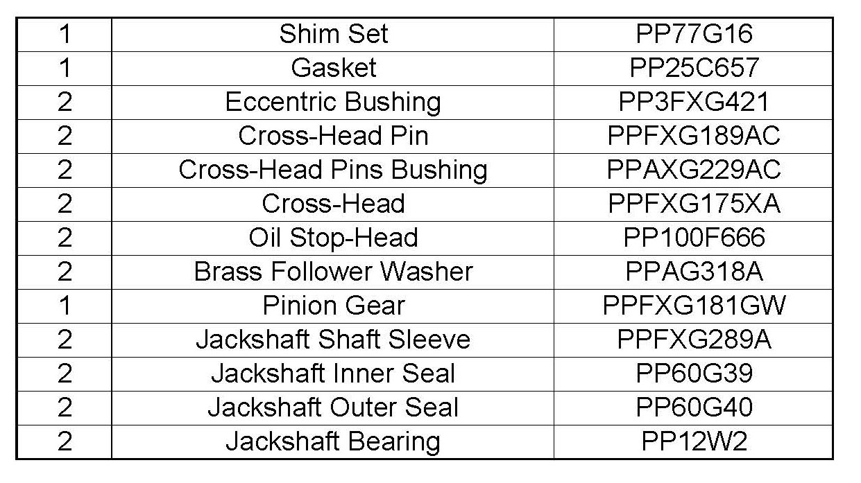
failing mud pump parts pricelist
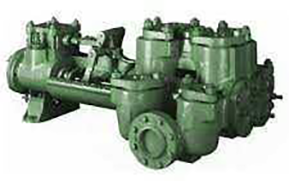
A mud pump is a reciprocating piston/plunger pump designed to circulate drilling fluid under high pressure (up to 7,500 psi (52,000 kPa)) down the drill string and back up the annulus. A duplex mud pump is an important part of the equipment used for oil well drilling.
Duplex mud pumps (two piston/plungers) have generally been replaced by the triplex pump, but are still common in developing countries. Two later developments are the hex pump with six vertical pistons/plungers, and various quintuplex’s with five horizontal piston/plungers. The advantages that Duplex mud pumps have over convention triplex pumps is a lower mud noise which assists with better Measurement while drilling and Logging while drilling decoding.
Use duplex mud pumps to make sure that the circulation of the mud being drilled or the supply of liquid reaches the bottom of the well from the mud cleaning system. Despite being older technology than the triplex mud pump, the duplex mud pumps can use either electricity or diesel, and maintenance is easy due to their binocular floating seals and safety valves.
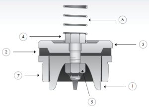
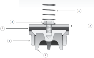
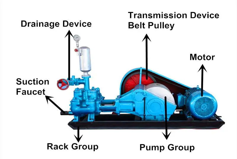
A mud pump is composed of many parts including mud pump liner, mud pump piston, modules, hydraulic seat pullers, and other parts. Parts of a mud pump:housing itself
Duplex pumps are used to provide a secondary means of fuel transfer in the event of a failure of the primary pump. Each pump in a duplex set is sized to meet the full flow requirements of the system. Pump controllers can be set for any of the following common operating modes:Lead / Lag (Primary / Secondary): The lead (primary) pump is selected by the user and the lag (secondary pump operates when a failure of the primary pump is detected.
Alternating: Operates per Lead / Lag (Primary / Secondary) except that the operating pump and lead / lag status alternate on consecutive starts. A variation is to alternate the pumps based on the operating time (hour meter) of the lead pump.
The mud pump piston is a key part for providing mud circulation, but its sealing performance often fails under complex working conditions, which shorten its service life. Inspired by the ring segment structure of earthworms, the bionic striped structure on surfaces of the mud pump piston (BW-160) was designed and machined, and the sealing performances of the bionic striped piston and the standard piston were tested on a sealing performance testing bench. It was found the bionic striped structure efficiently enhanced the sealing performance of the mud pump piston, while the stripe depth and the angle between the stripes and lateral of the piston both significantly affected the sealing performance. The structure with a stripe depth of 2 mm and angle of 90° showed the best sealing performance, which was 90.79% higher than the standard piston. The sealing mechanism showed the striped structure increased the breadth and area of contact sealing between the piston and the cylinder liner. Meanwhile, the striped structure significantly intercepted the early leaked liquid and led to the refluxing rotation of the leaked liquid at the striped structure, reducing the leakage rate.
Mud pumps are key facilities to compress low-pressure mud into high-pressure mud and are widely used in industrial manufacture, geological exploration, and energy power owing to their generality [1–4]. Mud pumps are the most important power machinery of the hydraulic pond-digging set during reclamation [5] and are major facilities to transport dense mud during river dredging [6]. During oil drilling, mud pumps are the core of the drilling liquid circulation system and the drilling facilities, as they transport the drilling wash fluids (e.g., mud and water) downhole to wash the drills and discharge the drilling liquids [7–9]. The key part of a mud pump that ensures mud circulation is the piston [10, 11]. However, the sealing of the piston will fail very easily under complex and harsh working conditions, and consequently, the abrasive mud easily enters the kinematic pair of the cylinder liner, abrading the piston surfaces and reducing its service life and drilling efficiency. Thus, it is necessary to improve the contact sealing performance of the mud pump piston.
As reported, nonsmooth surface structures can improve the mechanical sealing performance, while structures with radial labyrinth-like or honeycomb-like surfaces can effectively enhance the performance of gap sealing [12–14]. The use of nonsmooth structures into the cylinder liner friction pair of the engine piston can effectively prolong the service life and improve work efficiency of the cylinder liner [15–17]. The application of nonsmooth grooved structures into the plunger can improve the performance of the sealing parts [18, 19]. The nonsmooth structures and sizes considerably affect the sealing performance [20]. Machining a groove-shaped multilevel structure on the magnetic pole would intercept the magnetic fluid step-by-step and slow down the passing velocity, thus generating the sealing effect [21–23]. Sealed structures with two levels or above have also been confirmed to protect the sealing parts from hard damage [24]. The sealing performance of the high-pressure centrifugal pump can be improved by adding groove structures onto the joint mouth circumference [25]. The convex, pitted, and grooved structures of dung beetles, lizards, and shells are responsible for the high wear-resistance, resistance reduction, and sealing performance [26–28]. Earthworms are endowed by wavy nonsmooth surface structures with high resistance reduction and wear-resistance ability [29]. The movement of earthworms in the living environment is very similar to the working mode of the mud pump piston. The groove-shaped bionic piston was designed, and the effects of groove breadth and groove spacing on the endurance and wear-resistance of the piston were investigated [30]. Thus, in this study, based on the nonsmooth surface of earthworms, we designed and processed a nonsmooth striped structure on the surface of the mud pump piston and tested the sealing performance and mechanism. This study offers a novel method for prolonging the service life of the mud pump piston from the perspective of piston sealing performance.
The BW-160 mud pump with long-range flow and pressure, small volume, low weight, and long-service life was used here. The dimensions and parameters of its piston are shown in Figure 1.
A mud pump piston sealing performance test bench was designed and built (Figure 3). This bench mainly consisted of a compaction part and a dynamic detection part. The compaction part was mainly functioned to exert pressure, which was recorded by a pressure gauge, to the piston sealed cavity. This part was designed based on a vertical compaction method: after the tested piston and the sealing liquid were installed, the compaction piston was pushed to the cavity by revolving the handle. Moreover, the dynamic detection part monitored the real-time sealing situation and was designed based on the pressure difference method for quantifying the sealing performance. This part was compacted in advance to the initial pressure P0 (0.1 MPa). After compaction, the driving motor was opened, and the tested piston was pushed to drive the testing mud to reciprocate slowly. After 1 hour of running, the pressure P on the gauge was read, and the pressure difference was calculated as , which was used to measure the sealing performance of the piston.
To more actually simulate the working conditions of the mud pump, we prepared a mud mixture of water, bentonite (in accordance with API Spec 13A: viscometer dial reading at 600 r/min ≥ 30, yield point/plastic viscosity radio ≤ 3, filtrate volume ≤ 15.0 ml, and residue of diameter greater than 75 μm (mass fraction) ≤ 4.0%), and quartz sand (diameter 0.3–0.5 mm) under complete stirring, and its density was 1.306 g/cm³ and contained 2.13% sand.
Figure 4 shows the effects of stripe depth and angle on the sealing performance of mud pump pistons. Clearly, the stripe depth should be never too shallow or deep, while a larger angle would increase the sealing performance more (Figure 4).
The standard piston and the bionic piston were numerically simulated using the academic version of ANSYS® Workbench V17.0. Hexahedral mesh generation method was used to divide the grid, and the size of grids was set as 2.5 mm. The piston grid division is shown in Figure 8, and the grid nodes and elements are shown in Table 3. The piston cup was made of rubber, which was a hyperelastic material. A two-parameter Mooney–Rivlin model was selected, with C10 = 2.5 MPa, C01 = 0.625 MPa, D1 = 0.3 MPa−1, and density = 1120 kg/m3 [32, 33]. The loads and contact conditions related to the piston of the mud pump were set. The surface pressure of the piston cup was set as 1.5 MPa, and the displacement of the piston along the axial direction was set as 30 mm. The two end faces of the cylinder liner were set as “fixed support,” and the piston and cylinder liner were under the frictional interfacial contact, with the friction coefficient of 0.2.
Figure 10 shows the surface pressures from the lip mouth to the root in the standard piston and the bionic piston. The surface pressure of the bionic piston surpasses that of the standard piston, and the pressure at the edge of each striped structure changes suddenly: the pressures at the striped structure of the bionic piston are far larger than at other parts. These results suggest the contact pressure between the edges of the striped structures and the cylinder liner is larger, and the four edges of the two striped structures are equivalent to a four-grade sealed lip mouth formed between the piston and the cylinder liner, which generates a multilevel sealing effect and thereby largely enhances the sealing effect of the piston.
To better validate the sealing mechanism of the bionic striped pistons, a piston’s performance testing platform was independently built and the sealed contact of the pistons was observed. A transparent toughened glass cylinder liner was designed and machined. The inner diameter and the assembly dimensions of the cylinder liner were set according to the standard BW-160 mud pump cylinder liners. The sealing contact surfaces of the pistons were observed and recorded using a video recorder camera.
(1)The bionic striped structure significantly enhanced the sealing performance of the mud pump pistons. The stripe depth and the angle between the stripes and the piston were two important factors affecting the sealing performance of the BW-160 mud pump pistons. The sealing performance was enhanced the most when the stripe depth was 2 mm and the angle was 90°.(2)The bionic striped structure can effectively enhance the contact pressure at the piston lips, enlarge the mutual extrusion between the piston and the cylinder liner, reduce the damage to the piston and cylinder liner caused by the repeated movement of sands, and alleviate the abrasion of abrasive grains between the piston and the cylinder liner, thereby largely improving the sealing performance.(3)The bionic striped structure significantly intercepted the leaked liquid, reduced the leakage rate of pistons, and effectively stored the leaked liquid, thereby reducing leakage and improving the sealing performance.(4)The bionic striped structure led to deformation of the piston, enlarged the width and area of the sealed contact, the stored lubricating oils, and formed uniform oil films after repeated movement, which improved the lubrication conditions and the sealing performance.
The bionic striped structure can improve the sealing performance and prolong the service life of pistons. We would study the pump resistance in order to investigate whether the bionic striped structure could decrease the wear of the piston surface.
PetroEngineering LLC sells spare parts, tools and accessories for mud pumps F-800/1000/1300/1600 manufactured by Qingzhou (Qingzhou), Rongsheng HRSB (RongSheng), Bomco (Bomko) from a consignment warehouse in Russia (Surgut, KhMAO) ), HongHua (HongHua).
Organization of a warehouse on the territory of Russia allows PetroEngineering LLC to promptly meet the Customer"s needs for the necessary spare parts and components for mud pumps.

IEQ Industries is here to provide for all your pump needs. We are an online resource that offers new Wheatley or GASO pumps as well as remanufactured versions. We also provide parts and service for current and obsolete Wheatley and GASO models. If you are experiencing problems with your current or out-of-date pump and require parts or assistance, look no further than WheatleyPump.com. We have the parts and service that you need.
The inventory at WheatleyPump.com is extensive and includes parts like plungers, valves and extension rods. If you need abrasion and resistant valves, tungsten carbide, chrome oxide plungers or plunger packing, turn to
WheatleyPump.com. We have these kinds of items in stock, and if we do not have the item you need in our inventory, we can use our connections to locate it for you. We appreciate the engineering of the Wheatley and GASO pumps, and our company is always eager to find and provide you with the best parts available.
Let our friendly customer service representatives guide you through the parts selection process. You can fill out our contact form or get in touch with us directly at 1.800.544.9053. Our objective is to get your pump working hard again so your business can thrive, and we work fast so your company"s downtime is minimized.
Don"t be daunted by all of the parts available for your Wheatley or GASO pumps. Take advantage of the accessories and online guides we offer on our easy-to-navigate website. At WheatleyPump.com, we are pumped about helping you.
Mud-Pump Gear Sets . . . . . . . . . . . . . . . . . . . . . . . . . . . . . . . . . . . . . . . . . . . . . . . . . . . . . . . . . . . . . . . . . 13

triplex mud pumps and triplex mud pump parts meet the industry standards established by the American Petroleum Institute (API). As a global supplier of quality oilfield equipment to the oil and gas industry, we ship our products around the world.
Besides triplex mud pumps and triplex mud pump parts, we supply drilling rigs, workover rigs, top drives, drilling equipment, blowout preventers, BOP control systems, choke and kill manifolds, well service pumps for well cementing and hydraulic fracturing, wellhead equipment, casing heads, tubing heads, X-mas trees, FC type gate valves, etc. Please visit our company website
We supply unitized mud pump packages driven by DC or AC electric motors or diesel engines for electric and mechanical drilling rigs. The client can select DC or AC motors and diesel engine brands such as Caterpillar, Detroit, Cummins or others. Our unitized mud pump packages including everything on the skid and usually they are ready to work at delivery.

GEHO slurry pumps from Weir Minerals Netherlands are put to the test in some of the most extreme environments the world has to offer. And they are expected to work without fail.
Blue and shiny, the piston diaphragm pump stands in the factory hall, ready to be shipped to China for use in an aluminum factory. “The pump, a digester feed pump, was built and tested here,” explains Marjo Cox, public relations manager at Weir Minerals Netherlands, situated in Venlo. “The design was tailored to provide optimum performance in its specific application. The pumps are installed by one of our own commissioning engineers in China. He then instructs the local people on maintenance and operation.”
“Broadly speaking our pumps are used for three applications in mining,” he continues. “Firstly, they are used for pumping slurry over long distances, from the mine or extraction area to a port or processing plant. Secondly, the pumps deliver slurry directly to the system for removing the mineral or ore from the rock. Finally, they are used for pumping residual products such as red mud [a waste product in bauxite processing] or fly ash to a dump or back into an unused mine shaft. On a global scale, we are the leading player in all three applications, in particular in pipeline transport, with a market share of more than 90 percent.”
The company has a long history in pumping liquids and slurries. Even before World War II, Weir Minerals Netherlands (then GEHO Pompen) was involved in the manufacture of pumps for discharging ground-water. The products developed by pumping ever- thicker liquids such as sewage sludge and industrial sludge, until by the 1960s the pumps were capable of pumping ore slurry.
Slurry is crushed raw materialmixed with water. The problem is that direct contact between abrasive slurry and moving parts in a pump quickly leads to wear. The development of the piston diaphragm pump by GEHO in the 1970s offered a solution. With this system, the slurry is separated from the vulnerable moving parts of the pump by a membrane. At the time, an entire test installation was built at the GEHO factory to study the behavior of bauxite and other mineral slurries.
The first customer for a GEHO piston diaphragm pump was the German aluminum manufacturer VAW, which in 1974 needed a system for use in the German Ruhr area. Customers such as Hoechst and Thyssen Stahl soon followed. Initial contacts were then established with North America, and a small network of international agents was formed.
“The world of mining is relatively close-knit,” says Cox. “Your reputation is your most valuable possession. It is essential that you deliver a top-line product in terms of quality, service life, operation, availability and of course reliability. If a pump shuts down, the whole system grinds to a halt.”
The international expansionof GEHO took on a new dimension in 1990 following its takeover by U.S. company Baker Hughes. In 1994, Baker Hughes transferred all pump production activities to the Scottish Weir Minerals (see sidebar). “Becoming part of an international organization was a logical step for GEHO,” Joosten says. “We were able to retain our identity, and we remained responsible for sales, production and development. But we also gained access to an inter-national infrastructure of Weir sister companies. We could profit from a wealth of knowledge and experience and from a financially powerful parent company that enabled us to participate in larger projects.”
One mega project in Brazil recently involved the delivery of 18 pumps, to be installed in two pump stations, for a 340-mile-long pipeline. Each pump weighs 80 tons and 125 semi-trailers will be needed to transport the pumps to the port.
“A pump is not a standard product,” Joosten emphasizes. “We make our designs taking into account the application, ambient factors and the type of slurry. Each slurry has its own characteristics. First a sample of the slurry is examined in our laboratory for rheological characteristics. Depending on the outcome, we advise on or select the relevant materials, ranging from standard steel through to solid titanium.”
“The circumstances are different wherever we operate,” he continues. “They range from –40°F in Alaska and Siberia to more than 100°F in New Guinea, 10,000 feet under the ground in South Africa up to 13,000 feet in the Andes. Such extreme conditions can influence, for example, the operation of the electronic control equipment. Via the lubricating oil that flows right around the pump, we can cool or heat the system.”
Given the highraw-material prices and the tremendous demand from emerging markets over the past decade, business has boomed at Weir. “Our strength has always been our ability to supply products quickly,” Joosten says. “But at one point it became difficult for us to obtain our materials from our suppliers of wrought and cast work and moving parts. We faced the bizarre situation that there was simply not enough steel available to make the pumps that had been ordered for iron ore mines. Because every pump is tailor-made, it is almost impossible to complete work in advance, and that leaves little time for our suppliers. We eventually solved the problem by buying capacity, enabling us to get the products in time.”
Joosten adds, “Pumps are constantly developing. I predict trends involving more energy-efficient and more process-specific pumps with tailor-made work, in particular for high-temperature pumping. And as it happens, we are specialists in tailor-made products. And of course, pumps must never fail.”

There are a lot of people who use the terms piston and plunger pump interchangeably. Granted, they are both positive displacement pumps and there are similarities, but their subtle differences are kind of a big deal when it comes to an operator’s desired performance, price, and pump longevity.
Plunger pumps have a reciprocating plunger (a type of rod). When it moves back and forth, it sucks liquid in through an inlet valve and forces it out the outlet valve. Plunger pumps have a stationary, high-pressure seal that is attached to the cylinder housing of the pump.
Piston pumps also have a reciprocating rod called a piston that moves back and forth to force liquid through a set of valves. Unlike a plunger pump, however, a piston pump’s seal is connected to the piston, meaning it moves in unison with the piston inside the cylinder housing.
From an engineering standpoint, it’s easy to understand that the main difference between piston and plunger pumps is the placement of the seals or O-rings. Again, the plunger pump’s seal is stationary while the piston pump’s seal moves with the piston.
When a reciprocating rod goes back and forth within either a piston or plunger pump, you have to seal it against the cavity wall so that it doesn’t lose compression. Because the seals of a plunger pump are not attached to a rod, it allows for less friction and higher pressure output. When the seal is connected to the moving part, as with a piston pump, the dynamic sliding action occurs along the walls of the housing, resulting in less pressure.
Here’s why. When a piston pump pushes a rod with an attached seal forward, you get friction that pushes back against the seal. Friction makes the seal want to react in the opposite direction of the motion, making the pump have to work harder to achieve more pressure.
A plunger pump has a smoother sliding action. Translation: less friction. In a plunger pump where the reciprocating rod doesn’t have an attached seal, the friction is in the same direction as the movement of the plunger. But the pressure is in the opposite direction, meaning they help to cancel each other out to some degree. Reduced friction means the motor doesn’t need to work as hard to achieve higher pressures.
Design for Manufacturability (DfM) comes into play when determining the durability of a pump’s design, especially in regards to which materials can be used where.
The material makeup of a pump’s housing and the reciprocating plunger or piston will have the greatest impact. In general, you want the component that has the greatest potential for wear to be as hard as possible to avoid scratches and a broken seal.
Common materials used in the pump industry include anodized aluminum, stainless steel, and brass. But the hardest available material used in some pump designs is ceramic. It doesn’t wear out over time like most metals, plus it has great chemical compatibility. It can be polished to a very consistent and smooth surface finish which is perfect for creating a tight seal.
Why does this matter? In a plunger pump, it’s the plunger that needs to seal against the cavity wall, meaning it should be the hardest material possible. In a piston pump, it’s the cavity walls that need to seal against the rod with the O-ring, meaning the cavity wall needs to be as strong as possible.
However, engineering and fabricating a thin, tube-like cavity wall out of ceramic or other material and making the inside of it perfectly smooth and consistent is a much greater challenge than fabricating the exterior of a perfectly smooth plunger out of those same materials. Even if it were possible to make the internal housing walls out of ceramic, its poor tensile strength would quickly lead to cracking and pump failure.
In other words, it’s much easier to make the plunger out of hard materials than it is to make the housing out of those same materials. As a result, plunger pumps can be engineered to be much more durable than piston pumps.
Many piston pumps require an oil bath. Some versions also have a second oil reservoir or oil pan with a wick to lubricate the backside of the piston seal. These reservoirs need to be refilled and maintained if you want to keep the pump operating as it should.
Many plunger pumps, like those manufactured by Pumptec, have oil that is contained in a sealed chamber and do not require draining or refilling of any oil reservoirs.
The more parts you have, the more maintenance is required. Plunger pumps have a relatively simple design, fewer parts, and require much less maintenance than piston pumps. Simply put, there’s less that can go wrong with a plunger pump.
What else results from fewer parts and a simpler design? Lower cost. Plunger pumps, in general, can have considerably lower up-front costs than piston pumps when comparing similar performance. Their total cost of ownership is typically less, too, especially when you factor in maintenance, repairs, or replacement over time.
If you haven’t guessed by now, we’re a bit biased toward plunger pumps. Many of the reasons stated here are why our company ventured into the industry in the first place: we saw the need for better durability and performance at a fair price point.
If you’re in the market for high-performance, high-pressure electric commercial pumps for your industry application, get in touch with our team of pump experts. We’re happy to talk through your needs and challenges to determine a solution.
Curious about some of the terms used in this article? We developed a helpful Pump Terms Glossary with common terms and relevant information. Click below to download your copy today.
Mechanical pumps serve in a wide range of applications such as pumping water from wells, aquarium filtering, pond filtering and aeration, in the car industry for water-cooling and fuel injection, in the energy industry for pumping oil and natural gas or for operating cooling towers and other components of heating, ventilation and air conditioning systems. In the medical industry, pumps are used for biochemical processes in developing and manufacturing medicine, and as artificial replacements for body parts, in particular the artificial heart and penile prosthesis.
When a pump contains two or more pump mechanisms with fluid being directed to flow through them in series, it is called a multi-stage pump. Terms such as two-stage or double-stage may be used to specifically describe the number of stages. A pump that does not fit this description is simply a single-stage pump in contrast.
In biology, many different types of chemical and biomechanical pumps have evolved; biomimicry is sometimes used in developing new types of mechanical pumps.
Pumps can be classified by their method of displacement into positive-displacement pumps, impulse pumps, velocity pumps, gravity pumps, steam pumps and valveless pumps. There are three basic types of pumps: positive-displacement, centrifugal and axial-flow pumps. In centrifugal pumps the direction of flow of the fluid changes by ninety degrees as it flows over an impeller, while in axial flow pumps the direction of flow is unchanged.
Some positive-displacement pumps use an expanding cavity on the suction side and a decreasing cavity on the discharge side. Liquid flows into the pump as the cavity on the suction side expands and the liquid flows out of the discharge as the cavity collapses. The volume is constant through each cycle of operation.
Positive-displacement pumps, unlike centrifugal, can theoretically produce the same flow at a given speed (rpm) no matter what the discharge pressure. Thus, positive-displacement pumps are constant flow machines. However, a slight increase in internal leakage as the pressure increases prevents a truly constant flow rate.
A positive-displacement pump must not operate against a closed valve on the discharge side of the pump, because it has no shutoff head like centrifugal pumps. A positive-displacement pump operating against a closed discharge valve continues to produce flow and the pressure in the discharge line increases until the line bursts, the pump is severely damaged, or both.
A relief or safety valve on the discharge side of the positive-displacement pump is therefore necessary. The relief valve can be internal or external. The pump manufacturer normally has the option to supply internal relief or safety valves. The internal valve is usually used only as a safety precaution. An external relief valve in the discharge line, with a return line back to the suction line or supply tank provides increased safety.
Rotary-type positive displacement: internal or external gear pump, screw pump, lobe pump, shuttle block, flexible vane or sliding vane, circumferential piston, flexible impeller, helical twisted roots (e.g. the Wendelkolben pump) or liquid-ring pumps
Drawbacks: The nature of the pump requires very close clearances between the rotating pump and the outer edge, making it rotate at a slow, steady speed. If rotary pumps are operated at high speeds, the fluids cause erosion, which eventually causes enlarged clearances that liquid can pass through, which reduces efficiency.
Hollow disk pumps (also known as eccentric disc pumps or Hollow rotary disc pumps), similar to scroll compressors, these have a cylindrical rotor encased in a circular housing. As the rotor orbits and rotates to some degree, it traps fluid between the rotor and the casing, drawing the fluid through the pump. It is used for highly viscous fluids like petroleum-derived products, and it can also support high pressures of up to 290 psi.
Vibratory pumps or vibration pumps are similar to linear compressors, having the same operating principle. They work by using a spring-loaded piston with an electromagnet connected to AC current through a diode. The spring-loaded piston is the only moving part, and it is placed in the center of the electromagnet. During the positive cycle of the AC current, the diode allows energy to pass through the electromagnet, generating a magnetic field that moves the piston backwards, compressing the spring, and generating suction. During the negative cycle of the AC current, the diode blocks current flow to the electromagnet, letting the spring uncompress, moving the piston forward, and pumping the fluid and generating pressure, like a reciprocating pump. Due to its low cost, it is widely used in inexpensive espresso machines. However, vibratory pumps cannot be operated for more than one minute, as they generate large amounts of heat. Linear compressors do not have this problem, as they can be cooled by the working fluid (which is often a refrigerant).
Reciprocating pumps move the fluid using one or more oscillating pistons, plungers, or membranes (diaphragms), while valves restrict fluid motion to the desired direction. In order for suction to take place, the pump must first pull the plunger in an outward motion to decrease pressure in the chamber. Once the plunger pushes back, it will increase the chamber pressure and the inward pressure of the plunger will then open the discharge valve and release the fluid into the delivery pipe at constant flow rate and increased pressure.
Pumps in this category range from simplex, with one cylinder, to in some cases quad (four) cylinders, or more. Many reciprocating-type pumps are duplex (two) or triplex (three) cylinder. They can be either single-acting with suction during one direction of piston motion and discharge on the other, or double-acting with suction and discharge in both directions. The pumps can be powered manually, by air or steam, or by a belt driven by an engine. This type of pump was used extensively in the 19th century—in the early days of steam propulsion—as boiler feed water pumps. Now reciprocating pumps typically pump highly viscous fluids like concrete and heavy oils, and serve in special applications that demand low flow rates against high resistance. Reciprocating hand pumps were widely used to pump water from wells. Common bicycle pumps and foot pumps for inflation use reciprocating action.
These positive-displacement pumps have an expanding cavity on the suction side and a decreasing cavity on the discharge side. Liquid flows into the pumps as the cavity on the suction side expands and the liquid flows out of the discharge as the cavity collapses. The volume is constant given each cycle of operation and the pump"s volumetric efficiency can be achieved through routine maintenance and inspection of its valves.
This is the simplest form of rotary positive-displacement pumps. It consists of two meshed gears that rotate in a closely fitted casing. The tooth spaces trap fluid and force it around the outer periphery. The fluid does not travel back on the meshed part, because the teeth mesh closely in the center. Gear pumps see wide use in car engine oil pumps and in various hydraulic power packs.
A screw pump is a more complicated type of rotary pump that uses two or three screws with opposing thread — e.g., one screw turns clockwise and the other counterclockwise. The screws are mounted on parallel shafts that have gears that mesh so the shafts turn together and everything stays in place. The screws turn on the shafts and drive fluid through the pump. As with other forms of rotary pumps, the clearance between moving parts and the pump"s casing is minimal.
Widely used for pumping difficult materials, such as sewage sludge contaminated with large particles, a progressing cavity pump consists of a helical rotor, about ten times as long as its width. This can be visualized as a central core of diameter x with, typically, a curved spiral wound around of thickness half x, though in reality it is manufactured in a single casting. This shaft fits inside a heavy-duty rubber sleeve, of wall thickness also typically x. As the shaft rotates, the rotor gradually forces fluid up the rubber sleeve. Such pumps can develop very high pressure at low volumes.
Named after the Roots brothers who invented it, this lobe pump displaces the fluid trapped between two long helical rotors, each fitted into the other when perpendicular at 90°, rotating inside a triangular shaped sealing line configuration, both at the point of suction and at the point of discharge. This design produces a continuous flow with equal volume and no vortex. It can work at low pulsation rates, and offers gentle performance that some applications require.
A peristaltic pump is a type of positive-displacement pump. It contains fluid within a flexible tube fitted inside a circular pump casing (though linear peristaltic pumps have been made). A number of rollers, shoes, or wipers attached to a rotor compresses the flexible tube. As the rotor turns, the part of the tube under compression closes (or occludes), forcing the fluid through the tube. Additionally, when the tube opens to its natural state after the passing of the cam it draws (restitution) fluid into the pump. This process is called peristalsis and is used in many biological systems such as the gastrointestinal tract.
Efficiency and common problems: With only one cylinder in plunger pumps, the fluid flow varies between maximum flow when the plunger moves through the middle positions, and zero flow when the plunger is at the end positions. A lot of energy is wasted when the fluid is accelerated in the piping system. Vibration and
Triplex plunger pumps use three plungers, which reduces the pulsation of single reciprocating plunger pumps. Adding a pulsation dampener on the pump outlet can further smooth the pump ripple, or ripple graph of a pump transducer. The dynamic relationship of the high-pressure fluid and plunger generally requires high-quality plunger seals. Plunger pumps with a larger number of plungers have the benefit of increased flow, or smoother flow without a pulsation damper. The increase in moving parts and crankshaft load is one drawback.
Car washes often use these triplex-style plunger pumps (perhaps without pulsation dampers). In 1968, William Bruggeman reduced the size of the triplex pump and increased the lifespan so that car washes could use equipment with smaller footprints. Durable high-pressure seals, low-pressure seals and oil seals, hardened crankshafts, hardened connecting rods, thick ceramic plungers and heavier duty ball and roller bearings improve reliability in triplex pumps. Triplex pumps now are in a myriad of markets across the world.
Triplex pumps with shorter lifetimes are commonplace to the home user. A person who uses a home pressure washer for 10 hours a year may be satisfied with a pump that lasts 100 hours between rebuilds. Industrial-grade or continuous duty triplex pumps on the other end of the quality spectrum may run for as much as 2,080 hours a year.
The oil and gas drilling industry uses massive semi trailer-transported triplex pumps called mud pumps to pump drilling mud, which cools the drill bit and carries the cuttings back to the surface.
One modern application of positive-displacement pumps is compressed-air-powered double-diaphragm pumps. Run on compressed air, these pumps are intrinsically safe by design, although all manufacturers offer ATEX certified models to comply with industry regulation. These pumps are relatively inexpensive and can perform a wide variety of duties, from pumping water out of bunds to pumping hydrochloric acid from secure storage (dependent on how the pump is manufactured – elastomers / body construction). These double-diaphragm pumps can handle viscous fluids and abrasive materials with a gentle pumping process ideal for transporting shear-sensitive media.
Devised in China as chain pumps over 1000 years ago, these pumps can be made from very simple materials: A rope, a wheel and a pipe are sufficient to make a simple rope pump. Rope pump efficiency has been studied by grassroots organizations and the techniques for making and running them have been continuously improved.
Impulse pumps use pressure created by gas (usually air). In some impulse pumps the gas trapped in the liquid (usually water), is released and accumulated somewhere in the pump, creating a pressure that can push part of the liquid upwards.
Instead of a gas accumulation and releasing cycle, the pressure can be created by burning of hydrocarbons. Such combustion driven pumps directly transmit the impulse from a combustion event through the actuation membrane to the pump fluid. In order to allow this direct transmission, the pump needs to be almost entirely made of an elastomer (e.g. silicone rubber). Hence, the combustion causes the membrane to expand and thereby pumps the fluid out of the adjacent pumping chamber. The first combustion-driven soft pump was developed by ETH Zurich.
It takes in water at relatively low pressure and high flow-rate and outputs water at a higher hydraulic-head and lower flow-rate. The device uses the water hammer effect to develop pressure that lifts a portion of the input water that powers the pump to a point higher than where the water started.
The hydraulic ram is sometimes used in remote areas, where there is both a source of low-head hydropower, and a need for pumping water to a destination higher in elevation than the source. In this situation, the ram is often useful, since it requires no outside source of power other than the kinetic energy of flowing water.
Rotodynamic pumps (or dynamic pumps) are a type of velocity pump in which kinetic energy is added to the fluid by increasing the flow velocity. This increase in energy is converted to a gain in potential energy (pressure) when the velocity is reduced prior to or as the flow exits the pump into the discharge pipe. This conversion of kinetic energy to pressure is explained by the
A practical difference between dynamic and positive-displacement pumps is how they operate under closed valve conditions. Positive-displacement pumps physically displace fluid, so closing a valve downstream of a positive-displacement pump produces a continual pressure build up that can cause mechanical failure of pipeline or pump. Dynamic pumps differ in that they can be safely operated under closed valve conditions (for short periods of time).
Such a pump is also referred to as a centrifugal pump. The fluid enters along the axis or center, is accelerated by the impeller and exits at right angles to the shaft (radially); an example is the centrifugal fan, which is commonly used to implement a vacuum cleaner. Another type of radial-flow pump is a vortex pump. The liquid in them moves in tangential direction around the working wheel. The conversion from the mechanical energy of motor into the potential energy of flow comes by means of multiple whirls, which are excited by the impeller in the working channel of the pump. Generally, a radial-flow pump operates at higher pressures and lower flow rates than an axial- or a mixed-flow pump.
These are also referred to as All fluid pumps. The fluid is pushed outward or inward to move fluid axially. They operate at much lower pressures and higher flow rates than radial-flow (centrifugal) pumps. Axial-flow pumps cannot be run up to speed without special precaution. If at a low flow rate, the total head rise and high torque associated with this pipe would mean that the starting torque would have to become a function of acceleration for the whole mass of liquid in the pipe system. If there is a large amount of fluid in the system, accelerate the pump slowly.
Mixed-flow pumps function as a compromise between radial and axial-flow pumps. The fluid experiences both radial acceleration and lift and exits the impeller somewhere between 0 and 90 degrees from the axial direction. As a consequence mixed-flow pumps operate at higher pressures than axial-flow pumps while delivering higher discharges than radial-flow pumps. The exit angle of the flow dictates the pressure head-discharge characteristic in relation to radial and mixed-flow.
Regenerative turbine pump rotor and housing, 1⁄3 horsepower (0.25 kW). 85 millimetres (3.3 in) diameter impeller rotates counter-clockwise. Left: inlet, right: outlet. .4 millimetres (0.016 in) thick vanes on 4 millimetres (0.16 in) centers
Also known as drag, friction, peripheral, traction, turbulence, or vortex pumps, regenerative turbine pumps are class of rotodynamic pump that operates at high head pressures, typically 4–20 bars (4.1–20.4 kgf/cm2; 58–290 psi).
The pump has an impeller with a number of vanes or paddles which spins in a cavity. The suction port and pressure ports are located at the perimeter of the cavity and are isolated by a barrier called a stripper, which allows only the tip channel (fluid between the blades) to recirculate, and forces any fluid in the side channel (fluid in the cavity outside of the blades) through the pressure port. In a regenerative turbine pump, as fluid spirals repeatedly from a vane into the side channel and back to the next vane, kinetic energy is imparted to the periphery,
As regenerative turbine pumps cannot become vapor locked, they are commonly applied to volatile, hot, or cryogenic fluid transport. However, as tolerances are typically tight, they are vulnerable to solids or particles causing jamming or rapid wear. Efficiency is typically low, and pressure and power consumption typically decrease with flow. Additionally, pumping direction can be reversed by reversing direction of spin.
Steam pumps have been for a long time mainly of historical interest. They include any type of pump powered by a steam engine and also pistonless pumps such as Thomas Savery"s or the Pulsometer steam pump.
Recently there has been a resurgence of interest in low power solar steam pumps for use in smallholder irrigation in developing countries. Previously small steam engines have not been viable because of escalating inefficiencies as vapour engines decrease in size. However the use of modern engineering materials coupled with alternative engine configurations has meant that these types of system are now a cost-effective opportunity.
Valveless pumping assists in fluid transport in various biomedical and engineering systems. In a valveless pumping system, no valves (or physical occlusions) are present to regulate the flow direction. The fluid pumping efficiency of a valveless system, however, is not necessarily lower than that having valves. In fact, many fluid-dynamical systems in nature and engineering more or less rely upon valveless pumping to transport the working fluids therein. For instance, blood circulation in the cardiovascular system is maintained to some extent even when the heart"s valves fail. Meanwhile, the embryonic vertebrate heart begins pumping blood long before the development of discernible chambers and valves. Similar to blood circulation in one direction, bird respiratory systems pump air in one direction in rigid lungs, but without any physiological valve. In microfluidics, valveless impedance pumps have been fabricated, and are expected to be particularly suitable for handling sensitive biofluids. Ink jet printers operating on the piezoelectric transducer principle also use valveless pumping. The pump chamber is emptied through the printing jet due to reduced flow impedance in that direction and refilled by capillary action.
Examining pump repair records and mean time between failures (MTBF) is of great importance to responsible and conscientious pump users. In view of that fact, the preface to the 2006 Pump User"s Handbook alludes to "pump failure" statistics. For the sake of convenience, these failure statistics often are translated into MTBF (in this case, installed life before failure).
In early 2005, Gordon Buck, John Crane Inc.’s chief engineer for field operations in Baton Rouge, Louisiana, examined the repair records for a number of refinery and chemical plants to obtain meaningful reliability data for centrifugal pumps. A total of 15 operating plants having nearly 15,000 pumps were included in the survey. The smallest of these plants had about 100 pumps; several plants had over 2000. All facilities were located in the United States. In addition, considered as "new", others as "renewed" and still others as "established". Many of these plants—but not all—had an alliance arrangement with John Crane. In some cases, the alliance contract included having a John Crane Inc. technician or engineer on-site to coordinate various aspects of the program.
Not all plants are refineries, however, and different results occur elsewhere. In chemical plants, pumps have historically been "throw-away" items as chemical attack limits life. Things have improved in recent years, but the somewhat restricted space available in "old" DIN and ASME-standardized stuffing boxes places limits on the type of seal that fits. Unless the pump user upgrades the seal chamber, the pump only accommodates more compact and simple versions. Without this upgrading, lifetimes in chemical installations are generally around 50 to 60 percent of the refinery values.
Unscheduled maintenance is often one of the most significant costs of ownership, and failures of mechanical seals and bearings are among the major causes. Keep in mind the potential value of selecting pumps that cost more initially, but last much longer between repairs. The MTBF of a better pump may be one to four years longer than that of its non-upgraded counterpart. Consider that published average values of avoided pump failures range from US$2600 to US$12,000. This does not include lost opportunity costs. One pump fire occurs per 1000 failures. Having fewer pump failures means having fewer destructive pump fires.
As has been noted, a typical pump failure, based on actual year 2002 reports, costs US$5,000 on average. This includes costs for material, parts, labor and overhead. Extending a pump"s MTBF from 12 to 18 months would save US$1,667 per year — which might be greater than the cost to upgrade the centrifugal pump"s reliability.
Pumps are used throughout society for a variety of purposes. Early applications includes the use of the windmill or watermill to pump water. Today, the pump is used for irrigation, water supply, gasoline supply, air conditioning systems, refrigeration (usually called a compressor), chemical movement, sewage movement, flood control, marine services, etc.
Because of the wide variety of applications, pumps have a plethora of shapes and sizes: from very large to very small, from handling gas to handling liquid, from high pressure to low pressure, and from high volume to low volume.
Typically, a liquid pump can"t simply draw air. The feed line of the pump and the internal body surrounding the pumping mechanism must first be filled with the liquid that requires pumping: An operator must introduce liquid into the system to initiate the pumping. This is called priming the pump. Loss of prime is usually due to ingestion of air into the pump. The clearances and displacement ratios in pumps for liquids, whether thin or more viscous, usually cannot displace air due to its compressibility. This is the case with most velocity (rotodynamic) pumps — for example, centrifugal pumps. For such pumps, the position of the pump should always be lower than the suction point, if not the pump should be manually filled with liquid or a secondary pump should be used until all air is removed from the suction line and the pump casing.
Positive–displacement pumps, however, tend to have sufficiently tight sealing between the moving parts and the casing or housing of the pump that they can be described as self-priming. Such pumps can also serve as priming pumps, so-called when they are used to fulfill that need for other pumps in lieu of action taken by a human operator.
One sort of pump once common worldwide was a hand-powered water pump, or "pitcher pump". It was commonly installed over community water wells in the days before piped water supplies.
In parts of the British Isles, it was often called the parish pump. Though such community pumps are no longer common, people still used the expression parish pump to describe a place or forum where matters of local interest are discussed.
Because water from pitcher pumps is drawn directly from the soil, it is more prone to contamination. If such water is not filtered and purified, consumption of it might lead to gastrointestinal or other water-borne diseases. A notorious case is the 1854 Broad Street cholera outbreak. At the time it was not known how cholera was transmitted, but physician John Snow suspected contaminated water and had the handle of the public pump he suspected removed; the outbreak then subsided.
Modern hand-operated community pumps are considered the most sustainable low-cost option for safe water supply in resource-poor settings, often in rural areas in developing countries. A hand pump opens access to deeper groundwater that is often not polluted and also improves the safety of a well by protecting the water source from contaminated buckets. Pumps such as the Afridev pump are designed to be cheap to build and install, and easy to maintain with simple parts. However, scarcity of spare parts for these type of pumps in some regions of Africa has diminished their utility for these areas.
Multiphase pumping applications, also referred to as tri-phase, have grown due to increased oil drilling activity. In addition, the economics of multiphase production is attractive to upstream operations as it leads to simpler, smaller in-field installations, reduced equipment costs and improved production rates. In essence, the multiphase pump can accommodate all fluid stream properties with one piece of equipment, which has a smaller footprint. Often, two smaller multiphase pumps are installed in series rather than having just one massive pump.
A rotodynamic pump with one single shaft that requires two mechanical seals, this pump uses an open-type axial impeller. It is often called a Poseidon pump, and can be described as a cross between an axial compressor and a centrifugal pump.
The twin-screw pump is constructed of two inter-meshing screws that move the pumped fluid. Twin screw pumps are often used when pumping conditions contain high gas volume fractions and fluctuating inlet conditions. Four mechanical seals are required to seal the two shafts.
These pumps are basically multistage centrifugal pumps and are widely used in oil well applications as a method for artificial lift. These pumps are usually specified when the pumped fluid is mainly liquid.
A buffer tank is often installed upstream of the pump suction nozzle in case of a slug flow. The buffer tank breaks the energy of the liquid slug, smooths any fluctuations in the incoming flow and acts as a sand trap.
As the name indicates, multiphase pumps and their mechanical seals can encounter a large variation in service conditions such as changing process fluid composition, temperature variations, high and low operating pressures and exposure to abrasive/erosive media. The challenge is selecting the appropriate mechanical seal arrangement and support system to ensure maximized seal life and its overall effectiveness.
Pumps are commonly rated by horsepower, volumetric flow rate, outlet pressure in metres (or feet) of head, inlet suction in suction feet (or metres) of head.
From an initial design point of view, engineers often use a quantity termed the specific speed to identify the most suitable pump type for a particular combination of flow rate and head.
The power imparted into a fluid increases the energy of the fluid per unit volume. Thus the power relationship is between the conversion of the mechanical energy of the pump mechanism and the fluid elements within the pump. In general, this is governed by a series of simultaneous differential equations, known as the Navier–Stokes equations. However a more simple equation relating only the different energies in the fluid, known as Bernoulli"s equation can be used. Hence the power, P, required by the pump:
where Δp is the change in total pressure between the inlet and outlet (in Pa), and Q, the volume flow-rate of the fluid is given in m3/s. The total pressure may have gravitational, static pressure and kinetic energy components; i.e. energy is distributed between change in the fluid"s gravitational potential energy (going up or down hill), change in velocity, or change in static pressure. η is the pump efficiency, and may be given by the manufacturer"s information, such as in the form of a pump curve, and is typically derived from either fluid dynamics simulation (i.e. solutions to the Navier–Stokes for the particular pump geometry), or by testing. The efficiency of the pump depends upon the pump"s configuration and operating conditions (such as rotational speed, fluid density and viscosity etc.)
For a typical "pumping" configuration, the work is imparted on the fluid, and is thus positive. For the fluid imparting the work on the pump (i.e. a turbine), the work is negative. Power required to drive the pump is determined by dividing the output power by the pump efficiency. Furthermore, this definition encompasses pumps with no moving parts, such as a siphon.
Pump efficiency is defined as the ratio of the power imparted on the fluid by the pump in relation to the power supplied to drive the pump. Its value is not fixed for a given pump, efficiency is a function of the discharge and therefore also operating head. For centrifugal pumps, the efficiency tends to increase with flow rate up to a point midway through the operating range (peak efficiency or Best Efficiency Point (BEP) ) and then declines as flow rates rise further. Pump performance data such as this is usually supplied by the manufacturer before pump selection. Pump efficiencies tend to decline over time due to wear (e.g. increasing clearances as impellers reduce in size).
When a system includes a centrifugal pump, an important design issue is matching the head loss-flow characteristic with the pump so that it operates at or close to the point of its maximum efficiency.
Most large pumps have a minimum flow requirement below which the pump may be damaged by overheating, impeller wear, vibration, seal failure, drive shaft damage or poor performance.
The simplest minimum flow system is a pipe running from the pump discharge line back to the suction line. This line is fitted with an orifice plate sized to allow the pump minimum flow to pass.
A more sophisticated, but more costly, system (see diagram) comprises a flow measuring device (FE) in the pump discharge which provides a signal into a flow controller (FIC) which actuates a flow control valve (FCV) in the recycle line. If the measured flow exceeds the minimum flow then the FCV is closed. If the measured flow falls below the minimum flow the FCV opens to maintain the minimum flowrate.
As the fluids are recycled the kinetic energy of the pump increases the temperature of the fluid. For many pumps this added heat energy is dissipated through the pipework. However, for large industrial pumps, such as oil pipeline pumps, a recycle cooler is provided in the recycle line to cool the fluids to the normal suction temperature.oil refinery, oil terminal, or offshore installation.
Engineering Sciences Data Unit (2007). "Radial, mixed and axial flow pumps. Introduction" (PDF). Archived from the original (PDF) on 2014-03-08. Retrieved 2017-08-18.
Tanzania water Archived 2012-03-31 at the Wayback Machine blog – example of grassroots researcher telling about his study and work with the rope pump in Africa.
C.M. Schumacher, M. Loepfe, R. Fuhrer, R.N. Grass, and W.J. Stark, "3D printed lost-wax casted soft silicone monoblocks enable heart-inspired pumping by internal combustion," RSC Advances, Vol. 4, pp. 16039–16042, 2014.
"Radial, mixed and axial flow pumps" (PDF). Institution of Diploma Marine Engineers, Bangladesh. June 2003. Archived from the original (PDF) on 2014-03-08. Retrieved 2017-08-18.
Quail F, Scanlon T, Stickland M (2011-01-11). "Design optimisation of a regenerative pump using numerical and experimental techniques" (PDF). International Journal of Numerical Methods for Heat & Fluid Flow. 21: 95–111. doi:10.1108/09615531111095094. Retrieved 2021-07-21.
Rajmane, M. Satish; Kallurkar, S.P. (May 2015). "CFD Analysis of Domestic Centrifugal Pump for Performance Enhancement". International Research Journal of Engineering and Technology. 02 / #02. Retrieved 30 April 2021.
Wasser, Goodenberger, Jim and Bob (November 1993). "Extended Life, Zero Emissions Seal for Process Pumps". John Crane Technical Report. Routledge. TRP 28017.
Australian Pump Manufacturers" Association. Australian Pump Technical Handbook, 3rd edition. Canberra: Australian Pump Manufacturers" Association, 1987. ISBN 0-7316-7043-4.


 8613371530291