
gardner denver mud pump manual manufacturer

Maintain Pump Reliability And Performance ...............i Maintenance Schedule.............................................11
SECTION 1................................................................ 1 Lube Oil Pump..........................................................18
Pressurized Pump Systems ...................................... 3 Main Bearings...........................................................21
Flammable, Hot, Cold Or Corrosive Fluidpumping.... 4 Crosshead Pins ........................................................24
Starting A New Pump ................................................ 8 Piston Rod ................................................................26
Gal. Per Liter Per Gal. Per Liter Per Pump shaft Input
Weight Complete Pump ............................................................................................................................. 17,410 lbs. (7897.04 kg)
Weight Complete Pump ............................................................................................................................. 21,650 lbs. (9820.27 kg)
Gal. Per Liter Per Gal. Per Liter Per Pump shaft Input
Weight Complete Pump .......................................................................................................................... 26,500 lbs. (12,020.19 kg)
Weight Complete Pump ........................................................................................................................... 40,500 lbs. (18370.48 kg)
Gal. Per Liter Per Gal. Per Liter Per Pump shaft Input
Weight Complete Pump .......................................................................................................................... 40,500 lbs. (18,370.48 kg)
Weight Complete Pump .......................................................................................................................... 41,750 lbs. (18,937.47 kg)
Gal. Per Liter Per Gal. Per Liter Per Pump shaft Input
Weight Complete Pump .......................................................................................................................... 46,250 lbs. (20,978.63 kg)
In 1859, Robert Gardner founded the Gardner Governor Company. The company was named for Gardner’s work with the centrifugal governor, a part used in industrial steam equipment. Initially, the company manufactured control equipment for steam engines.
In the 1890s, the company began to expand its product line, creating steam and mud pumps. To support growing production, the company merged with the Denver Rock Drill Manufacturing Company in 1927 to form the Gardner-Denver Company.
The newly merged companies served a wide range of industries. Gardner-Denver Company manufactured equipment for oil wells, mining and construction, in addition to its current steam and pump offerings. Around this time, Gardner-Denver Company also began to manufacture portable and industrial air compressors.
In the 1940s, Gardner-Denver Company installed asbestos-containing pumps on Navy ships. These ships ranged from aircraft carriers, such as the USS Franklin D. Roosevelt, to destroyers, such as the USS Glennon. Many of these ships were in commission until the early 1990s, potentially exposing workers to asbestos parts for several decades.
Gardner-Denver Company’s production for the Navy included air compressors and mud pumps. Both pieces of machinery contained asbestos components, including gaskets and insulation packing. These components were standard in this era to provide tight seals, as well as heat- and pressure-resistance.
By the 1980s, Gardner-Denver Company stopped using asbestos as the mineral became more strictly regulated. For many asbestos companies, legal troubles began around this time.
In 1979, Texas-based electrical manufacturer, Cooper Industries, acquired the company. However, Cooper Industries separated in 1994. The company, now known as Gardner Denver, Inc., became independent once more. In 2019, Gardner Denver and Ingersoll Rand, another asbestos company, announced plans to merge.
The company’s pumps, which contained asbestos gaskets and packing, were widely used on Naval ships. Asbestos products were used in machinery to withstand pressurized and heated conditions.
Historic product manuals confirm the presence of braided asbestos packing in Gardner Denver’s mud pumps. Asbestos packing was used in pumps to insulate the stuffing box, which was used to prevent fluid from leaking out of moving parts in pumps. The stuffing box materials had to be replaced frequently.
Gardner Denver air compressors also contained asbestos. In air compressors, asbestos gaskets were used to provide a seal between separate components. These parts also required maintenance and replacement.
Workers responsible for servicing air compressors and mud pumps are among the most likely to be exposed to asbestos. During machinery maintenance, asbestos fibers became airborne and could then be inhaled.
Gardner Denver and OPI genuine pump parts are manufactured to original tolerances and designed for optimum dependability. Design and material innovations are the result of years of experience with hundreds of different pump applications. Reliability in materials and quality assurance are incorporated in our genuine replacement parts. Your authorized Gardner Denver and OPI distributor offers all the backup you’ll need. A worldwide network of authorized distributors provides the finest product support in the pump industry. Your local authorized distributor maintains a large in-
ventory of genuine parts and he is backed up for emergency parts by direct access to the Gardner Denver Machinery Inc. Master Distribution Center (MDC) in Memphis, Tennessee. Your authorized distributor can support your Gardner Denver and OPI pump needs with trained parts specialists to assist you in selecting the correct replacement parts. Authorized distributor service technicians are factory– trained and skilled in pump maintenance and repair. They are ready to respond and assist you by providing fast, expert maintenance and repair services.
For the location of your local authorized Gardner Denver and OPI distributor refer to the yellow pages of your phone directory or contact: Distribution Center: Gardner Denver Machinery Inc. Master Distribution Center 5585 East Shelby Drive Memphis, TN 38141 Phone: (901) 542–6100 Fax: (901) 542–6159
INSTRUCTIONS FOR ORDERING REPAIR PARTS When ordering parts, specify Pump MODEL and SERIAL NUMBER (see nameplate on unit). The Serial Number is also stamped on top of the cylinder end of the frame (cradle area). All orders for Parts should be placed with the nearest authorized distributor. Where NOT specified, quantity of parts required per pump or unit is one (1); where more than one is required
per unit, quantity is indicated in parenthesis. SPECIFY EXACTLY THE NUMBER OF PARTS REQUIRED. DO NOT ORDER BY SETS OR GROUPS. To determine the Right Hand and Left Hand side of a pump, stand at the power end. Right Hand and Left Hand are indicated in parenthesis following the part name, i.e. (RH) & (LH).
FOREWORD Gardner Denver and OPI pumps are the result of advanced engineering and skilled manufacturing. To be assured of receiving maximum service from this machine the owner must exercise care in its operation and maintenance. This book is written to give the operator and maintenance department essential information for day–to–day operation, maintenance and adjustment. Careful adherence to these instructions will result in economical operation and minimum downtime.
TABLE OF CONTENTS Maintain Pump Reliability and Performance . . . . . . . . . . . . . . . . . . . . . . . . . . . . . . . . . . . . . . . . . . . . . . . . . . . . . . . . . . . . i Instructions For Ordering Repair Parts . . . . . . . . . . . . . . . . . . . . . . . . . . . . . . . . . . . . . . . . . . . . . . . . . . . . . . . . . . . . . . . . i Foreword . . . . . . . . . . . . . . . . . . . . . . . . . . . . . . . . . . . . . . . . . . . . . . . . . . . . . . . . . . . . . . . . . . . . . . . . . . . . . . . . . . . . . . . . . ii Index . . . . . . . . . . . . . . . . . . . . . . . . . . . . . . . . . . . . . . . . . . . . . . . . . . . . . . . . . . . . . . . . . . . . . . . . . . . . . . . . . . . . . . . . . . . . iv SECTION 1, Danger Notices . . . . . . . . . . . . . . . . . . . . . . . . . . . . . . . . . . . . . . . . . . . . . . . . . . . . . . . . . . . . . . . . . . . . . . . . 1 SECTION 2, Installation & Operating Instructions . . . . . . . . . . . . . . . . . . . . . . . . . . . . . . . . . . . . . . . . . . . . . . . . . . . . . . 7 SECTION 3, Routine Maintenance & Service Instructions . . . . . . . . . . . . . . . . . . . . . . . . . . . . . . . . . . . . . . . . . . . . . 15 SECTION 4, Dimensions & Running Clearances . . . . . . . . . . . . . . . . . . . . . . . . . . . . . . . . . . . . . . . . . . . . . . . . . . . . . 30
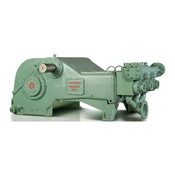
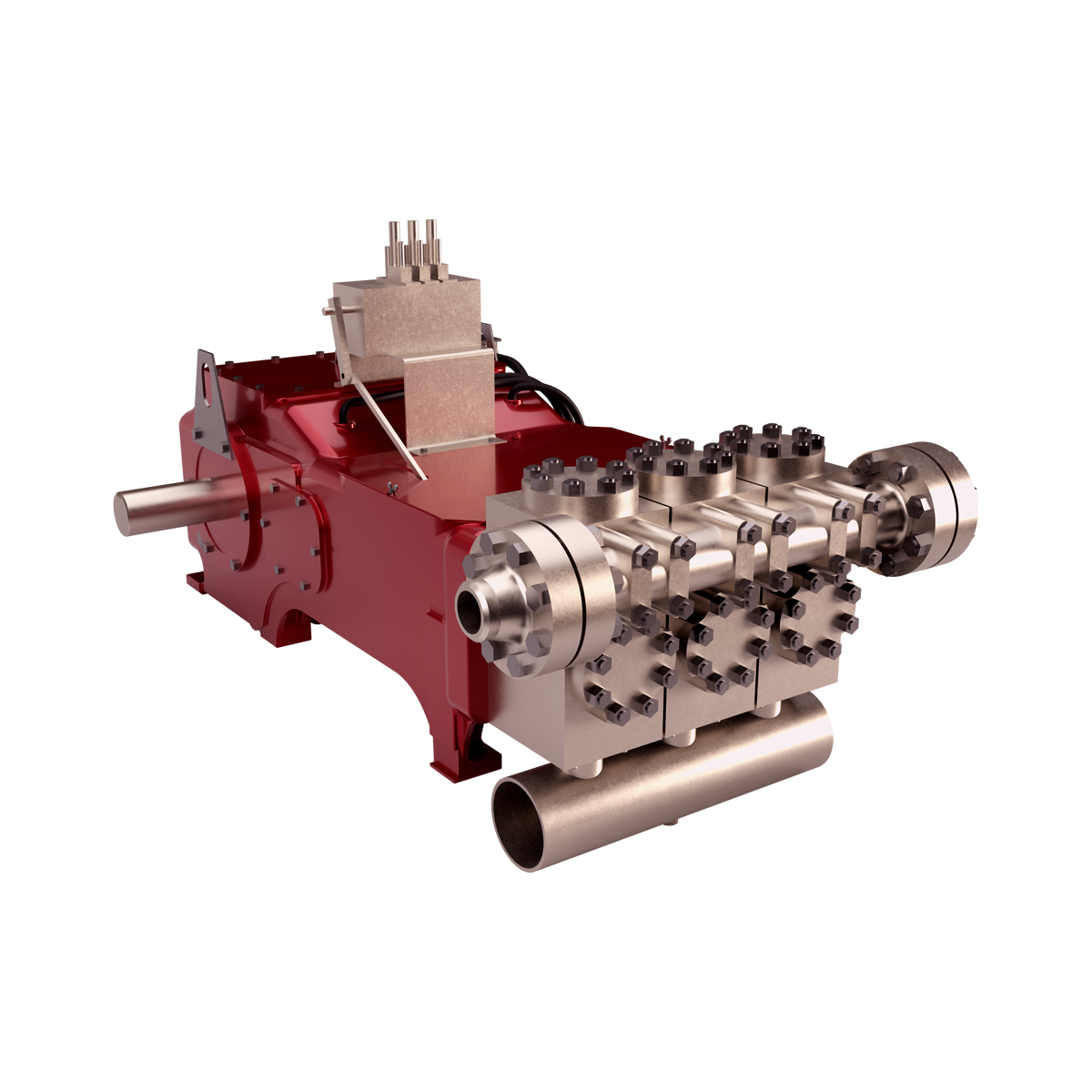
PZ Pump Outline . . . . . . . . . . . . . . . . . . . . . . . . . . . . . . . . . . . . . . . . . . . . . . . . . . . . . . . . . . . . . . . . . . 33
Pump, Lube Oil . . . . . . . . . . . . . . . . . . . . . . . . . . . . . . 17 Push Rods . . . . . . . . . . . . . . . . . . . . . . . . . . . . . . . . . . 23
SECTION 1 DANGER NOTICES personnel to refresh their memories in safe procedures and practices. Please read the following DANGER NOTICES before moving or operating the pump or any pump package unit equipment. Reciprocating pumps are machines capable of producing high fluid pressures and flow rates and are designed to be used with proper care and caution by trained, experienced operators. TO AVOID PERSONAL INJURY, DEATH AND/OR EQUIPMENT DAMAGE, READ AND THOROUGHLY UNDERSTAND THE FOLLOWING DANGER NOTICES PLUS THE ENTIRE OPERATING AND SERVICE MANUAL BEFORE ATTEMPTING TO MOVE OR OPERATE THE PUMP. Contact a Gardner Denver Machinery service representative if you are unable to comply with any of the danger notices or procedures described in these documents. Closely examine the data plate upon pump delivery to become thoroughly familiar with the operating limits for this pump model. The pump must never be operated at speeds, pressures or horsepower exceeding the maximum values shown on the data plate or at speeds below the minimum shown. Failure to observe the operating limits shown on the data plate could result in personal injury, death, and/or equipment damage and will void the warranty. Alterations to the pump, or application of the pump outside the data plate limits, must not be made without Gardner Denver Machinery written approval together with a new data plate, as dangerous operating conditions could result. THE DANGER NOTICE AND DATA PLATES PROVIDED ON THE EQUIPMENT MUST NOT BE REMOVED, PAINTED OVER, HIDDEN OR DEFACED. They must be replaced if they become damaged or unreadable. Provisions should be made to have the following written danger notices plus the pump operating and service manual readily available to operators and maintenance personnel. In addition, copies of all pump system accessory component (e.g. pressure relief valve, pulsation dampener, suction stabilizer, engine, electric motor, etc.) operating and service manuals should be readily available for operator and maintenance personnel use. Read and follow all the precautions and instructions contained in these manuals. If any of these documents are lost or become illegible they must be replaced immediately. The danger notices plus the operating and service manuals should be reread periodically by both operators and maintenance
Keep in mind that full operator attention and alertness are required when operating high pressure pumping equipment. Operators should not begin or continue operations when tired, distracted or under the influence of alcohol or any type of prescription or nonprescription drugs. The timely replacement of expendable parts and any other worn or damaged parts can prevent equipment damage and possible injury. The original parts used in Gardner Denver pumps are designed and tested to exacting standards to provide high quality performance and durability. Your best insurance in maintaining these characteristics is to use genuine Gardner Denver replacement parts. A broad range of danger notices are covered on these pages, however, they cannot substitute for training, experience and common sense in the safe operation of high pressure pumping equipment. HAMMER LUG FASTENERS
On pumps or pump package units equipped with hammer lug connectors and/or hammer lug valve covers the following precautions must be observed to avoid personal injury, death and/or equipment damage due to contact with the hammer, hammer bar, broken parts from the hammer, hammer bar or lugs or other objects propelled by hammer blows. When tightening or loosening hammer lug connectors and valve covers, operators or maintenance personnel should: S
Heavy equipment including pumps, pump package units and components should only be moved or lifted by trained, experienced operators, who are physically and mentally prepared to devote full attention and alertness to the moving and lifting operations. An operator should be fully aware of the use, capabilities, and condition of both the equipment being moved and the equipment being used to move it.
All pump covers must be securely fastened in proper position at all times when the pump is operating to avoid personal injury or death from moving parts. In addition, all moving parts on the entire pump package, including but not limited to engine or motors, drive shafts, belts, chains, pulleys, gears, etc., must be equipped with guards or covers, which must also be securely fastened in proper position at all times when the equipment is operating.
Failure to follow safe and proper pump, pump package or component lifting or moving procedures can lead to personal injury, death and/or equipment damage from shifting, falling or other unexpected or uncontrolled equipment movements. Make sure the hoist, lift truck, ropes, slings, spreader, or other lifting equipment you are using is in good condition and has a rated lifting capacity equal to or greater than the weight being lifted. Lifting devices must be checked frequently for condition and continued conformance to rated load capacity. They should then be tagged with the inspected capacity together with the date of inspection. Fully assembled pumps and pump package units are heavy and should only be moved using the specified lifting lugs or attachments. Many individual components have lifting eyes or lugs which must not be used to lift assemblies, as they are designed to bear the weight of the component only. Before lifting the individual component check to insure the lifting attachment is firmly secured to the component with undamaged, properly torqued fasteners, sound welds, or other secure attachments. Examine the lifting eyes, lugs, slots, holes or other projections to insure they are not cracked, otherwise damaged or badly worn. The repair of existing or addition of new welded lifting eyes, lugs or other projections should only be performed by experienced, qualified welders. Package units should be lifted with spreaders connected to the lifting attachments normally built into the package unit support skid. Packages too large to lift fully assembled should be separated into smaller loads.
For these smaller loads the lifting devices should be fastened to the lifting attachments normally built into the individual motor, engine, pump or transmission/ torque converter, or their separate support skids. When lifting subassembled components, for example a suction stabilizer attached to suction piping or a discharge pulsation dampener attached to a strainer cross and piping, use special lifting slings designed to safely support the combined weight of the components. If a crane or hoist is being used to lift large components or assemblies, one or more persons should assist the operator from the ground with guide lines attached to the equipment being moved to properly position it and prevent uncontrolled movement. When you start to lift a pump, package unit, subassemblies or individual components and you observe the equipment is tilting, or appears unbalanced, lower the equipment and adjust the lifting device to eliminate these improper lifting conditions before proceeding to move the equipment. It is poor practice and dangerous to allow the equipment to pass over or close to your body or limbs. Be prepared to move quickly out of danger if equipment starts to fall, slip or move unexpectedly toward you. PRESSURIZED PUMP SYSTEMS
Never place a shut–off valve or any other component between the pump discharge connection and the pressure relief valve. Make sure the pressure relief valve is installed so any pressurized relief discharge from the valve is directed away from possible contact with people or equipment. The relief valve must be set to relieve at a pressure equal to or below the maximum pressure values shown on the pump data plate. However, if a component is used in the discharge system with a lower rated pressure capability than that listed on the pump data plate, the pressure relief valve must be set to relieve at a pressure equal to or below the rated capability of the lowest rated component. Before starting the pump every time, check to insure:
Fluids under high pressure can possess sufficient energy to cause personal injury, death and/or equipment damage either through direct contact with escaping fluid streams or by contact with loose objects the pressurized fluid propels. Operating a pump against a blocked or restricted discharge line can produce excessive pressures in the entire discharge system, which can damage or burst discharge system components.
Never operate a pump without a properly sized pressure relief valve located in the flowing discharge line immediately adjacent to the pump discharge connection.
Check all fluid end discharge system components including pipe, connections, elbows, threads, fasteners, hoses, etc., at least once every six months to confirm their structural adequacy. With time, wear, corrosion and fatigue can reduce the strength of all components. Magnetic iron and steel components should be checked with magnetic particle or dye penetrant crack detection equipment. Nonmagnetic materials should be checked for cracks with dye penetrants. All metallic components should also be visually checked during these inspections for signs of corrosion. If a component shows evidence of cracking or loss of material due to corrosion it must be replaced with a new part. Continually monitor suction and discharge hose assemblies when the pump is operating for leakage, kinking, abrasion, corrosion or any other signs of wear or damage.
Worn or damaged hose assemblies should be replaced immediately. At least every six months examine hose assemblies internally for cut or bulged tube, obstructions and cleanliness. For segment style fittings, be sure that the hose butts up against the nipple shoulder, the band and retaining ring are properly set and tight and the segments are properly spaced. Check for proper gap between nut and socket or hex and socket. Nuts should swivel freely. Check the layline of the hose to be sure that the assembly is not twisted. Cap the ends of the hose with plastic covers to keep them clean until they are tested or reinstalled on the pump unit. Following this visual examination, the hose assembly should be hydrostatically tested, on test stands having adequate guards to protect the operator, per the hose manufacturer’s proof test procedure. Fluid end component inspections should be performed more frequently than every six months if pressures above 2500 psi are used in the discharge system or if corrosive, flammable or hot (over 110_ F) fluids are being pumped. Proper stuffing box packing selection is important for safe pump operation. Contact a Gardner Denver Machinery service representative for assistance in selecting the proper packing before beginning operation. Before starting the pump for the first time and periodically thereafter check the pump, suction and discharge system fastener torques versus the values listed in the Operating and Service Manual tables to insure proper tightness. Over and under torquing can damage threaded pipes, connections and fasteners, which may lead to component damage and/or failure. Replace all components found to be damaged or defective. On pumps equipped with stuffing boxes, the gland must be engaged by at least three (3) threads to hold the discharge pressure of the pump.
Do not attempt to service, repair, adjust the plunger packing or otherwise work on the pump while the unit is operating. Shut off the pump drive motor or engine and relieve the fluid pressure in the pump suction and discharge systems before any work or investigation is performed on the pump or pump systems. Block the crankshaft from turning and make certain that all pump drive motor or engine start switches or starter
controls are clearly tagged with warnings not to start the pump while repair work is in process. Whenever the pump is operating, continually monitor the entire suction, discharge and pump lubricating systems for leaks. Thoroughly investigate the cause for leakage and do not operate the pump until the cause of the leak has been corrected. Replace any parts which are found to be damaged or defective. When a gasketed joint is disassembled for any reason, discard the used gasket and replace it with a new, genuine Gardner Denver gasket before reassembling the joint. Due to the high working pressures contained by the fluid cylinder, discharge manifold and discharge piping, welding on these components is not recommended. If welding on the discharge system cannot be avoided, only experienced, qualified welders should be used. In addition, the welded part should be hydrostatically proof tested in the shop with water or hydraulic fluid to one and one half times maximum discharge system working pressure, with no observable fluid leakage, before the part is reinstalled in the pump system. In summary, high pressure fluid streams can possess sufficient energy to cause personal injury, death and/or equipment damage. These results can occur either through direct contact with the fluid stream or by contact with loose objects the fluid stream has propelled, if the pump system is improperly used, or if the fluid is misdirected, or allowed to escape from defective or improperly maintained equipment. FLAMMABLE, HOT, COLD OR CORROSIVE FLUID PUMPING
Extreme caution must be exercised by trained and experienced operators when flammable, hot, cold or corrosive fluids are being pumped, in order to avoid personal injury, death and/or equipment damage due to explosion, fire, burn, extreme cold or chemical attack. Never operate a pump which is pumping hydrocarbons or other flammable, hot, cold, or corrosive fluids when any part of the pump, suction system or discharge system is leaking. Stop the pump immediately if any leakage, other than a few drops per minute of packing weepage, is observed. Keep all flame, sparks, or hot objects away from any part of the pump, suction system, or discharge system. Shield the pump, suction
system and discharge system to prevent any flammable, hot, cold or corrosive fluid leakage from dripping or spraying on any components, flame, sparks, hot objects or people. Inspect the plungers, packing, gaskets and seals for fluid leakage frequently and replace all worn or leaking parts. Selection of the proper gaskets, seals and stuffing box packing is even more critical when flammable, hot, cold or corrosive fluids are being pumped than when other, inherently less dangerous fluids are used. Contact a Gardner Denver Machinery service representative for assistance in selecting the proper gaskets, seals and packing before beginning operation. Since some packing seepage into the cradle area is inevitable, the drain at the bottom of the cradle must be connected to a drain line which conducts the fluid leakage to a collection container located in a protected area. The entire drain system and container must be constructed of materials resistant to attack from the pumped fluid or from explosion or fire of the pumped fluid. Heavy duty cradle covers must be securely fastened in the proper position on the pump at all times when the pump is operating. If the pumped fluid releases harmful, explosive or flammable vapors the covers must be vented to conduct the fumes away from the pump unit to a nonhazardous area. Before beginning pumping operations or starting the pump power source (whether an engine or electric motor) check the atmosphere all around the pumping site for the presence of flammable or explosive vapors. Do not begin operation and stop ongoing operation if flammable or explosive vapors are detected. Hot surfaces, sparks, electric current or engine exhaust could ignite flammable or explosive vapors. Each engine used as a power source on pumping units where flammable or explosive vapors could form should be equipped with an air inlet shut–off. If flammable or explosive vapors are present in the pumping site atmosphere, an engine could continue to run on these vapors even after the engine fuel line is shut–off if an air inlet shut–off is not used. In addition, on pumping units used where flammable or explosive vapors could form, all electric motors used as power sources must be of explosion proof construction and all electrical components and wiring must meet the current National Electrical Code for explosive atmospheres. These precautions must be taken to avoid possible personal injury, death and/or equipment damage from explosion, fire or burns.
Extreme caution must be exercised if any type of wand, gun, nozzle or any other pressure and flow directing device is attached to the pump discharge system for use in jetting, blasting, cleaning, etc. This type of equipment must be used with utmost care by trained, experienced operators. High pressure fluid streams can either by direct contact or by propelling loose objects, cause serious personal injury or death to the operators and/or other persons. Pressure or flow directing devices often receive pressurized flow through flexible hoses, which can burst if they are kinked, cut, abraded or are otherwise worn, damaged or pressured above their rated capacity. Protect the hose and connections from damage by people, objects and vehicles. A broken, cut or otherwise burst hose can release pressurized fluid which may cause personal injury, death and/or equipment damage. High pressure fluid from hand held or hand directed pressure and flow directing devices may overpower an operator’s ability to control or direct the device, which could lead to personal injury, death and/or equipment damage. The operator must brace against the backward thrust of a hand held device. In addition, a safety harness or safety net must be used when working in an area where the operator could be injured in a fall. Stand to the side of any tubing or container being sprayed to avoid back spray and never operate a hand held device above shoulder level. Never direct the pressurized fluid stream at yourself or any other person, control valves, the pump, pump drive, suction or discharge systems. The pressurized stream can cause serious personal injury or death and can also change valve or control settings which could dangerously increase the delivery pressure to the pressure and flow directing device. When operating a pressure and flow directing device, use only equipment which automatically shuts off flow when an operator releases hand or foot pressure on the pressurized flow trigger control to prevent injury if the operator is overpowered or becomes disabled. Check to insure this automatic shut–off equipment is operating properly before every use and never circum-
Full operator attention and alertness are required when operating this equipment to avoid personal injury, death and/or equipment damage. The operators should take frequent rest breaks and cease operations when they become tired or distracted. Before the equipment is started, the work area must be inspected and properly prepared to avoid personal injury, death and/or damage to equipment. Make sure the work area is checked for hazardous fumes, has adequate ventilation for engine exhaust and sufficient drainage for released fluid. Check the work area for electrical equipment, connections, outlets, fixtures, or lines. If any are present they must be made water tight and the electrical power to these devices must be shut off to avoid electrical shocks from fluid contact. The work area should be clearly marked and roped off to keep unauthorized people and vehicles from entering. Remove all loose parts, tools and equipment from the work area before beginning operation. All pressure containing devices including wands, nozzles, guns, hoses, connections, etc., should be regularly checked for condition. These components should all be tagged with their tested pressure capabilities together with the date testing was performed. Always be aware of the pressure level in the system and never connect any equipment to the system which has a rated or tested pressure capability below the system operating pressure. The equipment must be shut down and the system pressure released before changing or disconnecting wands, nozzles, guns, hoses, connections or any other pressurized system components. All pressure containing devices including wands, nozzles, guns, connections, etc., plus all automatic shut–off, pressure and control equipment should be treated with care. Protect them from damage by people, objects and vehicles. Never lay them in dirt, mud, ice or other loose material which could plug the fluid opening or interfere with their operation. Never use the wand, nozzle, gun, etc. to pry loose material off items being cleaned. Before starting operation in a cold environment, check to make sure there is no ice in the fluid system and re-
After you have selected and purchased these components, follow the manufacturer’s instructions completely in their use. In summary, high pressure jetting, blasting and cleaning are inherently dangerous, as the pressures and flow rates needed to remove scale, clean, etc. are sufficient to cause personal injury, death and/or equipment damage resulting from, but not limited to, any of the conditions described in the above Danger Notices. STARTING A NEW PUMP – Pumps are shipped from the factory without oil in the crankcase. The hood should be removed and the power end examined and cleaned if necessary. The pump may have been in storage or in the yard for some time and as a consequence dirt may have entered the crankcase. Parts may have been robbed from the pump during storage and not replaced. All nuts and screws should be tightened. The jackshaft bearings have been supplied with grease at the factory and no grease should be added at this time, unless bearings have been disturbed. Be sure all valves in the discharge line are open. No valve should be installed between the pump and pressure relief valve in discharge line. To prevent excessive wear on the fluid pistons and packing when starting, remove a suction valve cover plate on each side of the fluid end and prime the pump. Pump should be started slowly, if possible, and should be operated for several hours with practically no discharge pressure. Check oil level as it may be necessary to add a small quantity of oil to compensate for that adhering to the walls of the crankcase and the moving parts. The pump may then gradually be brought up to full speed and full working pressure. Watch for undue heating or abnormal noise in the working parts. Check all joints in the suction line to be sure there are no air leaks.
Reference to Parts List covering the Model Pump being serviced is recommended in connection with this Instruction Manual. Repair Parts Lists with Sectional Views are available from any Gardner Denver Sales and Service Office. When ordering parts, always give size and serial number of pump. Always use genuine Gardner Denver parts. For efficient, factory–trained service, consult a Gardner Denver Service Specialist.
When working on any pump, be certain there is no fluid pressure on either suction or discharge side. Pressure on fluid end might move pump and cause damage or injury to personnel. It is recommended that all suction valve covers be removed to avoid fluid pressure building up against pistons or plungers.
LOCATION – Pump should be set level and solidly supported. The drive should be accurately aligned. Pump should be placed as close to the slush pit as possible to keep the suction line short and direct. Locate pump as low as possible to maintain a minimum suction lift to the centrifugal charging pump which is used because of the high speed of this type of mud pump. When the pump skid or master skid is to be bolted or welded to a platform or deck in the field, it is necessary that the following “Final Shimming Procedure” be followed. Final Shimming Procedure – After the pump skid or master skid has been bolted or welded to a stationary platform or deck, proceed as follows: a.
SUCTION LINE – Suction pipe or hose to centrifugal charging pump should be a minimum of 12 inches (304.8 mm) diameter and as short as possible. Always use eccentric reducers when reducing suction pipe size. Suction line should slope up toward the charging pump at uniform grade to prevent air pockets being formed. Suction line must be absolutely tight as any air leaking into the line will reduce the capacity of the pump and cause a hydraulic hammer or knock. If it is necessary to have bends in the suction line they should have long radius sweeps and be kept to a minimum in quantity. 10–40 PSI suction required.
Suction line should be supported near centrifugal charging pump to keep strain from breaking the casing at suction flange. At least one section of hose in the suction line is desirable to isolate pulsations or vibration. Total suction line should be as short as installation conditions permit. THIS IS IMPORTANT. A suction strainer is recommended for the suction line of every pump. It must be checked frequently and cleaned whenever necessary. A commercial strainer may be installed in suction line ahead of the pump. It is recommended that a 50 PSI (3.515 kg/cm2) gauge with a needle valve for protection be installed in the suction line at the discharge of the centrifugal charging pump. This gauge will indicate if pump is charging or if suction valves are not working properly. RELIEF VALVES – The pump should be protected from excess discharge pressure by a 3 inch (76.2 mm) relief valve. This valve should be installed in a vertical position in a tee mounted directly onto either end of discharge manifold or discharge cross.
If more than one pump is used, a pressure release valve should be furnished for each pump. A hand–operated pressure release valve should be installed in discharge line following the relief valve, with discharge line leading to mud tank. This valve is used to bleed air from discharge line in starting. It is also used to relieve pressure in starting more than one pump in parallel. SURGE CHAMBER – A surge chamber is essential. One MUST be used for protection to surface equipment and to reduce pulsations when pumping gaseous mud. A nitrogen–charged pressure–bag type surge chamber is recommended. The surge chamber must be kept properly charged, as instructed by the manufacturer.
the lower slide. This means better lubrication and quiet operation. Lube oil pumps are not automatic reversing. If PZ pumps are to be run in reverse direction, refer to “Lube Oil Pump”. Pumps are shipped from the factory without oil in the crankcase. The hood should be removed and the power end examined and cleaned if necessary. The pump may have been in storage or in the yard for some time, and as a consequence, dirt may have entered the crankcase. Drain all water accumulated in the bottom of the crankcase. Fill crankcase with oil of proper grade to the proper level. Quantity shown on lubrication data plate indicates the approximate oil requirements. All nuts and cap screws should be checked for tightness. It is recommended that the fluid end of the pump be primed to prevent excessive wear on the fluid pistons and liners when starting. PRIMING IS IMPORTANT! IT LUBRICATES THE PISTONS IN THE LINERS. Pump should be started slowly but not run below half of rated speed. Recheck oil level as it may be necessary to add a small quantity of oil to crankcase and the moving parts. The pump may then be gradually brought up to full speed and full working pressure. Check all joints in the suction line to be sure there are no air leaks. LUBRICATION – All power end working parts are lubricated by the oil in the crankcase. Check oil level frequently. Selection of oil is to be taken from the recommendations given in FIGURE 2 and on the pump data plate. Local conditions and practice may also influence the selection. Essential additives are foam and oxidation inhibitors. Oil is to be added as required to maintain oil level near the top of the oil level indicator on the side of the frame.
STARTING A NEW PUMP – It is recommended that the drive be arranged to turn the pump in the direction indicated by arrow shown on the sectional view in this book, on outline prints, and indicated on pump frame. This book provides for crosshead load to be carried on
Time between oil changes depends upon local and/or operating conditions. Under normal circumstances, if the crankcase is kept clean, it should not be necessary to change oil more than once in 1000 hours of operation. Many operators change oil after each well drilled. Oil should be changed if found to be dirty or contaminated with mud or water. This is especially important for the PZ pump, as the oil lubricated roller bearings will be damaged by contamination. An oil change is comparatively inexpensive, as the approximate crankcase capacities are shown in FIGURE 4.
An 80_ F (27_ C) crankcase oil temperature rise over ambient air temperature is typical for the pumps covered by this manual when operating at or near rated horsepower.
Some operating conditions and/or oil brands produce excessive oil foaming, even when the specified GL–5 oils containing antifoaming additives are used. Oil foaming can cause pump damage, as oil bubbles will not lubricate moving parts properly. If significant oil foaming occurs, contact Gardner Denver Marketing or Service, (217) 222–5400, for the current factory recommended defoamant to be added to the lubricating oil.
Oil is constantly circulated through a renewable element filter and then through a heat exchanger, when one is used, by means of a rotary pump driven from the main gear. Oil is discharged into an elevated oil feed trough, from which it is conducted to jackshaft and main bearings. Oil also flows from the trough to lubricate the connecting rod bearings.
In order to assure proper lubrication, the PZG, PZH & PZJ pumps should not be run under 10 RPM for more than a few minutes at a time without providing additional lubrication from an extra external oil pump. The PZK & PZL pumps should not be run under 40 RPM. The oils normally used in large mud pumps are quite viscous at lower temperatures. When starting cold, the pump should be started slowly and brought up to operating speed slowly. This practice will assure proper lubrication of all working parts before pump is fully loaded. OIL FILTER – A replaceable element oil filter is located inside the pump crankcase. Filter mounting flange is on the outside (FIGURE 5, page 10), making it possible to replace the element by removing end plate. Only the oil within the filter case will be spilled when element is withdrawn. Filter element should be replaced each time crankcase oil is changed or every 1000 hours of operation.
not otherwise drain due to small size of tubes, capillary attraction, and the horizontal position of the heat exchanger mounting. Water should not be admitted to the heat exchanger as long as oil temperatures do not exceed 160_ F(71.1_ C). A dial thermometer is standard equipment on all PZ pumps. Salt water can be used for cooling. Zinc anode plugs are provided for corrosion protection. These plugs are to be replaced when they have been corroded away. DIRECTION OF ROTATION – The PZ pump MUST be driven in the direction as shown by arrow on sectional view, outline drawing and on pump frame. The oil pump on PZG, PZH and PZJ models is a nonreversible pump. If the PZ pump must be run in reverse direction, see “Lube Oil Pump”, page 17.
Filter element is protected from excessive internal oil pressure by a relief valve between it and the oil pump. On units equipped with a heat exchanger, oil flows through the oil filter before going through the heat exchanger. HEAT EXCHANGER (Optional Equipment) – For Models PZG, PZH & PZJ a bronze heat exchanger can be provided to keep crankcase oil temperature at 160_ F (71.1_ C) by means of an automatic water control valve. This valve has a sensing probe in the crankcase oil, and it monitors water to the heat exchanger to maintain oil temperature within close limits. Water must be drained from the heat exchanger during freezing weather. Ruptured water tubes will admit water into the oil, with resulting damage to working parts of the pump. Cooling water can be drained from the heat exchanger by removing water connections and blowing compressed air into upper opening. Water will then flow from the lower opening. Air is necessary, as water will
Running pump in the prescribed direction will also result in proper lubrication and quiet operation as load on crosshead will be carried on the lower side. CROSSHEAD DRAINS – Model PZ pumps are equipped with two plugged drain openings below and in front of the crossheads. These openings are to drain any possible leakage from the oil stop head packings which collects in a small reservoir built into the frame. This area should be drained daily. It is recommended that these openings be piped together and a valve installed to simplify the daily draining. Failure to drain this area could result in drilling mud in the power end and possible premature failure. OPERATION – For normal drilling operation, the pumps are to be run at the ratings listed in FIGURE 6, FIGURE 7 and FIGURE 8, pages 12, 13 and 14. In no case should pressure exceed that shown for each diameter piston – to do so would subject working parts to operating loads in excess of those for which they were designed, resulting in reduced life.
Weight Complete Pump . . . . . . . . . . . . . . . . . . . . . . . . . . . . . . . . . . . . . . . . . . . . . . . . . . . . . . . . 17,410 Lbs. (7897.04 kg) Gear Ratio . . . . . . . . . . . . . . . . . . . . . . . . . . . . . . . . . . . . . . . . . . . . . . . . . . . . . . . . . . . . . . . . . . . . . . . . . . . . . . . . . 4.625 to 1 Length Over Skid . . . . . . . . . . . . . . . . . . . . . . . . . . . . . . . . . . . . . . . . . . . . . . . . . . . . . . . . . . . . . . . 120 Inches (3048.0 mm) Width Over Skid . . . . . . . . . . . . . . . . . . . . . . . . . . . . . . . . . . . . . . . . . . . . . . . . . . . . . . . . . . . . . . . . . 50 Inches (1270.0 mm) Width Over Jackshaft . . . . . . . . . . . . . . . . . . . . . . . . . . . . . . . . . . . . . . . . . . . . . . . . . . . . . . . . 80.20 Inches (2037.08 mm)
Weight Complete Pump (w/Cast Frame) . . . . . . . . . . . . . . . . . . . . . . . . . . . . . . . . . . . . . . . . . . 21,650 Lbs. (9820.27 kg) Weight Complete Pump (w/Fabricated Frame)(Also Includes New Cylinders) . . . . . . . . . . 22,035 Lbs. (9994.9 kg) Gear Ratio . . . . . . . . . . . . . . . . . . . . . . . . . . . . . . . . . . . . . . . . . . . . . . . . . . . . . . . . . . . . . . . . . . . . . . . . . . . . . . . . . . . 4.5 to 1 Length Over Skid . . . . . . . . . . . . . . . . . . . . . . . . . . . . . . . . . . . . . . . . . . . . . . . . . . . . . . . . . . . . 193.62 Inches (4917.9 mm) Width Over Skid . . . . . . . . . . . . . . . . . . . . . . . . . . . . . . . . . . . . . . . . . . . . . . . . . . . . . . . . . . . . . . . . . 89 Inches (2260.6 mm) *
Weight Complete Pump (w/Cast Frame) . . . . . . . . . . . . . . . . . . . . . . . . . . . . . . . . . . . . . . . . . 26,500 Lbs. (12 020.19 kg) Weight Complete Pump (w Fabricated Frame) . . . . . . . . . . . . . . . . . . . . . . . . . . . . . . . . . . . 25,520 Lbs. (11 575.67 kg) Gear Ratio . . . . . . . . . . . . . . . . . . . . . . . . . . . . . . . . . . . . . . . . . . . . . . . . . . . . . . . . . . . . . . . . . . . . . . . . . . . . . . . . . . 4.48 to 1 Length Over Skid . . . . . . . . . . . . . . . . . . . . . . . . . . . . . . . . . . . . . . . . . . . . . . . . . . . . . . . . . . 224.12 Inches (5692.648 mm) Width Over Skid . . . . . . . . . . . . . . . . . . . . . . . . . . . . . . . . . . . . . . . . . . . . . . . . . . . . . . . . . . . . . . . . . 96 Inches (2438.4 mm) MODEL PZK – 1350 H.P. TRIPLEX MUD PUMP 3 3 3 3
Weight Complete Pump (w/Cast Frame) . . . . . . . . . . . . . . . . . . . . . . . . . . . . . . . . . . . . . . . . . 40,500 Lbs. (18 370.48 kg) Weight Complete Pump (w/Fabricated Frame) . . . . . . . . . . . . . . . . . . . . . . . . . . . . . . . . . . . . 41,870 Lbs. (18 991.9 kg) Gear Ratio . . . . . . . . . . . . . . . . . . . . . . . . . . . . . . . . . . . . . . . . . . . . . . . . . . . . . . . . . . . . . . . . . . . . . . . . . . . . . . . . . . 4.38 to 1 Length Over Skid . . . . . . . . . . . . . . . . . . . . . . . . . . . . . . . . . . . . . . . . . . . . . . . . . . . . . . . . . . . . . 222.5 Inches (5651.5 mm) Width Over Skid . . . . . . . . . . . . . . . . . . . . . . . . . . . . . . . . . . . . . . . . . . . . . . . . . . . . . . . . . . . . . . . . . 96 Inches (2438.4 mm) Width Over Jackshaft . . . . . . . . . . . . . . . . . . . . . . . . . . . . . . . . . . . . . . . . . . . . . . . . . . . . . . . . . . . 104 Inches (2641.6 mm) *
Weight Complete Pump (w/Cast Frame) . . . . . . . . . . . . . . . . . . . . . . . . . . . . . . . . . . . . . . . . . 40,500 Lbs. (18 370.48 kg) Weight Complete Pump (w/Fabricated Frame) . . . . . . . . . . . . . . . . . . . . . . . . . . . . . . . . . . . . 41,870 Lbs. (18 991.9 kg) Gear Ratio . . . . . . . . . . . . . . . . . . . . . . . . . . . . . . . . . . . . . . . . . . . . . . . . . . . . . . . . . . . . . . . . . . . . . . . . . . . . . . . . . . 4.38 to 1 Length Over Skid . . . . . . . . . . . . . . . . . . . . . . . . . . . . . . . . . . . . . . . . . . . . . . . . . . . . . . . . . . . . . 222.5 Inches (5651.5 mm) Width Over Skid . . . . . . . . . . . . . . . . . . . . . . . . . . . . . . . . . . . . . . . . . . . . . . . . . . . . . . . . . . . . . . . . . 96 Inches (2438.4 mm) Width Over Jackshaft . . . . . . . . . . . . . . . . . . . . . . . . . . . . . . . . . . . . . . . . . . . . . . . . . . . . . . . . . . . 104 Inches (2641.6 mm)
SECTION 3 ROUTINE MAINTENANCE & SERVICE INSTRUCTIONS Remove hood and crosshead inspection plates for access to working parts. Before working on inside of crankcase, it is necessary to drain the oil. Lube oil pump mounting brackets and piping connections are below the oil level. Mark all parts during dismantling so they can be returned to their original position during reassembly. It is highly recommended that pump be removed to a machine shop if major work is to be done on power end. *
If the jackshaft bearing is to be replaced, the outer race and roller assembly can be driven or pressed out of the bearing housing. The jackshaft bearings should be replaced if any of the rollers or races shows damage or if they are excessively worn. A noisy bearing indicates bearing damage, requiring replacement. Check clearances by inserting feeler gauge between the roller and inner race with bearing assembled on the shaft and in the housing. This check can be made with the bearing temporarily assembled out of the pump, but with inner race on jackshaft. See recommended running clearances on pages 27 and 28. To mount the new bearings, heat the inner race in oil to about 300_ F (148.8_ C) and slip it in on the shaft against the bearing spacer ring. Be certain the spacer ring is in place with the chamfered end of the bore over the large fillet on the jackshaft. The inner race and the spacer are to be assembled snugly against the shaft shoulder. The shaft can be reinstalled in the frame.
JACKSHAFT – To remove the jackshaft, it is necessary to remove all sheaves from the jackshaft. Then remove bearing end plates and bearing housings from both sides of pump. Support each end of jackshaft while removing bearing housings. The jackshaft can be moved horizontally until the pinion teeth clear the teeth of the eccentric gear. The jackshaft can now be removed from either side of the pump. The jackshaft bearings are of the straight roller type with roller and cage assembly held in the flanged outer race. The inner race is not flanged. The outer race and roller assembly will slide over the inner race which remains on the jackshaft. Both bearings are identical. The straight roller bearings permit the jackshaft to float endwise. Thrust loads are carried on the spherical main bearings. Main bearings will be covered as a separate item. The safest way to remove the inner race of the jackshaft bearing from the shaft is by the careful use of heat. Do not overheat to the point where race is discolored. Be careful not to damage the bearing spacer ring between the inner race and the shoulder on the shaft.
To reassemble the jackshaft in the pump, it is necessary to reverse procedure of removal. The teeth of the pinion can mesh in only one direction, therefore, the jackshaft is not interchangeable end for end in the pump unless gear and eccentric assembly is also reversed. Reversal of the complete gearset is permissible after gear or pinion teeth become badly worn. Since gear is not on centerline of the frame, it is necessary to move the oil pump and filter from original position to the opposite side of the frame and repipe as required. Recommended direction of rotation of the pump provides that inner ends or apex of gear and pinion teeth lead. This means that when viewing from the hood opening, the inner ends of the gear teeth point upward toward the jackshaft and the inner ends of the pinion teeth point toward the gear. Gears may be reversed, but direction of rotation of the pump MUST NOT BE REVERSED. See paragraph “Lube Oil Pump” on the following page. Pump should be run in the direction
shown on sectional view and indicated by arrow on outline print and frame. Apex of teeth will follow after gearset has been reversed. After jackshaft is in place with the pinion in mesh with the gear, install the bearing housings with the outer bearing race and roller assemblies in them. Be careful to keep dirt from the bearings during assembly. The housing is to be started on the bearing and in the bore of the frame and lightly driven in. Be sure the gasket is on the housing. Long threaded studs may be used to pull the housing into the frame bore. It is well to work both housings at the same time after they have been well started over the bearing inner race. This will minimize end thrust on the gear teeth. Before assembling bearing plates into the frame, the bearing oil troughs should be installed. The bearing housing can be rotated in the frame, making it easy to level oil trough properly. Top of oil trough is to be level. The PZG pump does not have oil trough.
Outer oil seals are to be placed in the bearing end plate after it is bolted to the bearing housing and frame. Coat inside of oil seal liberally with bearing grease. The seal is to be installed with garter spring to inside, toward bearing. Permanently bolt jackshaft bearing housings and their end plates to the frame. LUBE OIL PUMP – The lube oil pump, part number 46C21, used in the PZG, PZH and PZJ pumps can be reversed in direction after the following procedure is completed. Remove the end cap from the oil pump opposite the shaft end, remove the drain plug screw opposite the oil pump discharge port. Install the drain plug screw in the hole provided 180o or opposite from the suction port. Reverse the suction and discharge lines to the lube oil pump and reverse the data tag “IN – ROTATION – OUT”. The drain plug screw must be installed in the pump body opposite the oil pump discharge port. Replace the end cap. The lube oil pump, part numbers 46C58 and 201PAH188, used in the PZK and PZL pumps can be reversed in direction. The low oil flow through the pump will reverse direction when shaft is rotated in reverse. Viewing the oil pump 46C58 from the shaft end, rotating the shaft clockwise, the right hand pump opening is the inlet. When rotating shaft counterclockwise, the left hand opening is the inlet and the right hand opening becomes the outlet. When shaft rotation of the 201PAH188 oil pump changes direction, the direction of flow changes without changing inlet and outlet port positions. CONNECTING RODS – The connecting rods are split into body and cap, and bolted together without shims. This construction is used to simplify installation and/or removal of eccentric and gear assembly.
The upper connecting rod bolt is inserted from the cap side to avoid interference with jackshaft. The lower bolt is inserted from body side to make nut easily accessible. Crosshead pins with bearing inner races can be removed without disturbing the connecting rods on PZG, PZH and PZJ pumps. On the PZK and PZL pumps, the hood must be removed and the connecting rods loosened from the cap and parted by about one inch (25.4 mm) before the center crosshead pin will clear the outside connecting rod. Crosshead pin bearings can be removed and replaced by means of a puller available from the factory. Refer to parts list. Always protect crosshead slide in frame by placing a block of wood under small end of connecting rod. If slide should be accidently damaged, be certain to stone
MAIN BEARINGS – These bearings are of the double– row spherical type. Inner race has a tapered bore. Main bearings can be replaced without removing eccentric assembly from the pump and without disturbing connecting rods. Remove bearings with cartridges from the eccentric shaft and frame as outlined in procedure covering removal of eccentric and gear assembly. Be sure to support eccentric securely in its original location. Remove lube oil pump gear to protect oil pump shaft as main gear might move during this operation. Main bearing is a slip fit in the bearing cartridge or carrier, and can be readily removed. Remove inner retainer ring from end of cartridge if it is necessary to drive the bearing from the cartridge.
Be careful not to damage the highly polished surface on which oil seals bear. Push rods are chrome plated and should be protected when the pump is painted. Paint will damage the oil stop head seals.
18. Bolt R.H. bearing end plat in place first. 19. Bolt L.H. bearing end plate in place. 20. Assemble the drive pinion on the shaft of the lube oil pump. 21. Remove all tools and loose parts from the crankcase. Remove the device use to support the weight of the eccentric assembly. 22. Replace lube oil pump. Put the hood back in place. Be sure the gasket is in good condition and in proper location. Bolt down securely. Use grease on frame flange to help keep hood gasket in place. 23. Do not forget to replace or renew the crankcase oil. Now is a good time for an oil change and a new filter element to protect the new bearings just installed. CROSSHEAD PINS
CROSSHEAD SLIDES – The crosshead slides are cast of tough bearing bronze. Top and bottom slides are interchangeable and are bolted into the frame. Slides are also interchangeable end for end. The operating load is carried on the lower shoe and slide when pump is run in prescribed direction. It is unlikely that upper slides will even require replacement unless damaged by accident. It is necessary to remove the jackshaft in order to reach the cap screws which hold the upper crosshead slides to the frame on early models. Later models are provided with openings on the outside of the frame to reach and remove these cap screws and nuts. Lower slides may eventually need to be replaced after long wear or if damaged. It is advisable to remove the crossheads as described above in order to reach the countersunk head cap screws which secure the slides to the frame. The nuts are on the outside and underneath the frame. Use of shims between the crosshead slides and the frame is not recommended as they may fret through. Use new slides instead of shimming. Slides can be removed through oil stop head openings in frame, or through crosshead inspection openings. OIL STOP HEADS – Oil stop heads keep the crankcase oil within the frame. They also keep mud and liner washing fluids from entering the crankcase. Oil stop packing consists of two identical seals mounted in adaptors. They are not adjustable. The inner seal lip is pointed inward toward the crankcase to strip oil from the push rod. The outer seal lip points outward toward liner to strip mud and/or water from the push rod. Be certain seals are properly installed. The seal adaptors, with seals in them, can be slipped off and on the push rods by removing the clamp holding piston rods against the push rods and separating the two flanges. Do not use a screwdriver or drift to separate the push rod and piston rod flanges. Turn the pump slightly. It is essential that oil stop head seals be replaced at the first indication of leakage. Oil leakage will be indicated by oil collecting on top of the liner washing water in the reservoir. If rig water is used for washing and run to a waste area, it is difficult to check the above method. If oil leakage is serious it will show up in a lower oil level in the crankcase. In this case oil must be added to the
crankcase as required until new oil stop seals can be installed. Leakage of mud and water into the crankcase will be indicated by a milky appearance of the crankcase oil. Mud will also be seen below oil stop heads on inside of crankcase through crosshead inspection plate openings. When mud is found in crankcase, oil should be changed. Drain and clean out crankcase before putting in the new oil. Replace seals in oil stop heads before running pump. It is recommended that oil stop head seals be changed every six months of operation, even though leakage is not evident. VALVE CHAMBERS – The PZ pump is equipped with individual valve chambers (cylinders). Valve chambers are secured to frame with high tensile strength studs. It is important that nuts on these studs be checked occasionally for tightness. A loose nut will eventually cause a stud to break under pulsating load. These connecting studs extend through the liner clamp flanges. Liner clamps are clamped by means of above studs against the liner flanges and serve to clamp liners tightly against valve chambers. A square rubber compound gasket seals end of liner against valve chamber. When replacing a valve chamber it is necessary to remove the discharge manifold. Also remove screws holding suction manifold to the chamber being replaced. Loosen, but do not remove suction manifold screws in the other two chambers. Suction manifold can be dropped enough to clear gaskets. These members are to be securely bolted to the new valve chamber before it is finally tightened against frame connecting flange. Be sure manifold gaskets are in place. LINER CLAMP AND LINERS – When liner clamps are reinstalled or replaced, it is advisable to check cylinder to frame stud nuts and tighten if necessary. Refer to page 29 for proper torques. Nuts holding liner clamps in place should not be overtightened as distortion of the clamp and liner bore may result. Recommended torque is shown on page 29. Change size of pistons and liners as volume and/or pressure requirements change. See rating charts, FIGURE 6, FIGURE 7 and FIGURE 8, pages 12, 13 and 14. Liners are replaced by removing the liner clamp. Liners should be cleaned and oiled after removal to protect against rusting during storage, so they can be used again. Pump liners are to be clean both inside and out when installed. Also clean the liner clamp bore and lightly oil all surfaces.
Use new gaskets when installing liners and be sure to clean all surfaces against which the gaskets fit. Liners or valve chambers may be cut by leaking gaskets. PISTONS – Single–acting pistons consist of a steel piston body with insert retained by a washer and snap ring. Pistons, with piston rods, can be removed or installed through suction valve opening after valve upper guide is removed by turning it 90_. Valve spring must also be removed. 7” pistons on PZG, PZJ and PZJ pumps must be removed through frame. It is recommended that a piston and rod assembly be kept ready for replacement. This is a practical time– saver. PISTON ROD – Piston rods are manufactured of high carbon steel. They are electrolytically plated to protect against corrosion. They are provided with a knurled section so rod can be held while tightening piston nut. It is important that piston rod nut be tightened to recommended torque shown on page 29. Piston rod to piston fit is straight. Piston fits against flange on piston rod with on “O” ring gasket to prevent leakage. Removal of piston is a simple operation since it is not driven up on taper. Keep piston rod to push rod clamps tight at all times to prevent damage to their connecting flanges and pilots. DO NOT use a screwdriver or cold chisel to separate the flanges – turn the pump slightly.
gal circulating pump to prevent splashing and being blown about. MAINTENANCE OF VALVES – In order to keep the pump in its best operating condition, it is necessary to examine the suction and discharge valves occasionally to see that excessive wear or cutting by the slush or mud has not impaired their efficiency. Any worn or damaged parts should be replaced. This is especially true with regard to the inserts. Standard inserts are made from urethane and are the part of the valve which should be changed most frequently. They are much cheaper than the valves and seats, and if the inserts are renewed as soon as they begin to fail, the more expensive steel parts will last much longer. Routine inspection of valves every two or three days is recommended. When removing a worn valve seat, use the Gardner– Denver puller powered with a hydraulic jack. Be careful to chain or tie the jack down as it will jump violently when the valve seat lets go. If it becomes necessary to resort to the use of heat or a cutting torch to remove a valve seat, the services of a man experienced in these operations is necessary. Before putting new seats in the pump, the tapered bore in the valve seat deck of the cylinder must be thoroughly cleaned with a wire brush. Wire brush should be used around the bore rather than up and down. Wipe the bore clean and do not use oil or grease. The bore must be clean and dry or seat may not seat properly.
PISTON WASHING SYSTEM – The piston washing system is vital to the satisfactory performance and life of pistons and liners. The complete system must be kept in good operating condition. Washing fluid should be maintained in good condition and should be replaced when contaminated to the point where free circulation is impaired. This is of utmost importance and should be impressed upon all operators of the pump.
Water supply lines should be permanently attached to the openings provided in the circulating pump and the tank. Water is then quickly available as a washing fluid or to flush ou


 8613371530291