
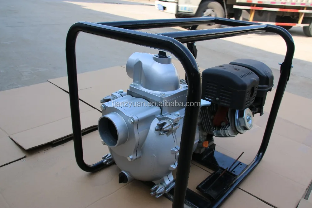
gas powered centrifugal mud pump free sample
Powered by Honda GX120 Commercial Engine gas. Replaced by newer model 338G-96. AMT 2" Diaphragm pumps features 2-stage, 44 to 1 gear reduction with a large diameter output gear and heavy duty ball bearing construction. Often referred to as Mud pumps, mudhog or Sludge pumps, diaphragm pumps are designed to pump mud, slurry, sewage, and thick water liquids that have the ability to flow. AMT IPT Diaphragm pumps are available with a choice of drivers to meet your application requirements. Phelps HoneyWagon Wastecorp
Honda gasoline engines. Built-in molded polyurethane flapper/check valve assures self-priming to 20 feet after initial prime. Heavy duty gear box is designed to operate pumps at 60 strokes per minute. Each unit includes a 2" NPT steel suction strainer, two 2" NPT nipples, and wheel kit with 10" semi-pneumatic transport wheels for portability. Pumps are designed for use with non-flammable liquids which are compatible with pump component materials. Mud Trash pumps Suction and discharge port size cannot be reduced.
Suction and discharge port size cannot be reduced. Due to positive pumping action of diaphragm pumps, by all mfr"s, the discharge is recommended to only be 25FT long unless oversized. Discharge can not be restricted. There is no relief valve.
15 Models below. Made in USA. Gas, Diesel or Electric diaphragm pump, or mud / sludge pump. Easily maneuverable, the gas diaphragm pump is built for performance; Ideal for seepage dewatering, high suction lift, cleaning septic tanks, pumping industrial waste and marine tanks, small wellpoint systems and dewatering in sandy, muddy waters. Honda or Briggs gasoline engine or Electric diaphragm pump with motor.
Diaphragm Mud pump Suction & discharge port size cannot be reduced. Cast aluminum construction with thermoplastic rubber diaphragm. Also called a mudhog. 90 degree rotatable base on all models to fit through narrow gates. As a alternate in a centrifugal pump dredge pump design see 316F-95 2" mud pumps. Trash pumps, centrifugal Dredge Pump. Hoses and accessories.

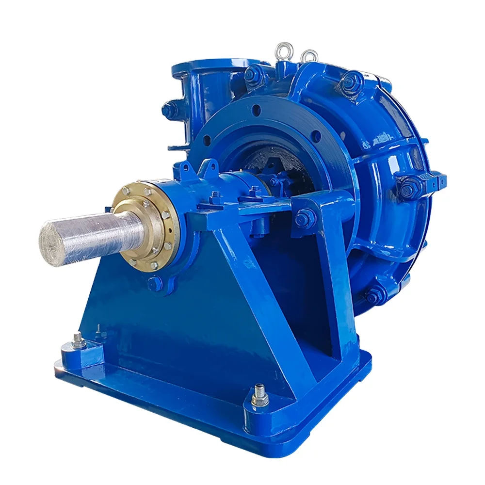
This rig features a Mission 4-by-5 centrifugal pump. Courtesy of Higgins Rig Co.Returning to the water well industry when I joined Schramm Inc. last year, I knew that expanding my mud pump knowledge was necessary to represent the company"s mud rotary drill line properly. One item new to me was the centrifugal mud pump. What was this pump that a number of drillers were using? I had been trained that a piston pump was the only pump of any ability.
As I traveled and questioned drillers, I found that opinions of the centrifugal pumps varied. "Best pump ever built," "What a piece of junk" and "Can"t drill more than 200 feet with a centrifugal" were typical of varying responses. Because different opinions had confused the issue, I concluded my discussions and restarted my education with a call to a centrifugal pump manufacturer. After that conversation, I went back to the field to continue my investigation.
For the past eight months, I have held many discussions and conducted field visits to understand the centrifugal pump. As a result, my factual investigation has clearly proved that the centrifugal pump has a place in mud rotary drilling. The fact also is clear that many drilling contractors do not understand the correct operational use of the pump. Following are the results of my work in the field.
High up-hole velocity - High pump flow (gpm) moves cuttings fast. This works well with lower viscosity muds - reducing mud expense, mixing time and creating shorter settling times.
Able to run a desander - The centrifugal"s high volume enables a desander to be operated off the pump discharge while drilling without adding a dedicated desander pump.
6. Sticky clays will stall a centrifugal pump"s flow. Be prepared to reduce your bit load in these conditions and increase your rpm if conditions allow. Yes, clays can be drilled with a centrifugal pump.
7. Centrifugal pumps cannot pump muds over 9.5 lbs./gal. Centrifugal pumps work best with a 9.0 lbs./gal. mud weight or less. High flow rate move cuttings, not heavy mud.
The goal of this article has been to increase awareness of the value of the centrifugal pump and its growing use. Although the centrifugal pump is not flawless, once its different operating techniques are understood, drilling programs are being enhanced with the use of this pump.
If you wish to learn more, please talk directly to centrifugal pump users. Feel free to call me at 314-909-8077 for a centrifugal pump user list. These drillers will gladly share their centrifugal pump experiences.

AfghanistanAlbaniaAlgeriaAmerican SamoaAndorraAngolaAnguillaAntarcticaAntigua and BarbudaArgentinaArmeniaArubaAustraliaAustriaAzerbaijanBahamasBahrainBangladeshBarbadosBelarusBelgiumBelizeBeninBermudaBhutanBoliviaBonaire, Sint Eustatius and SabaBosnia and HerzegovinaBotswanaBouvet IslandBrazilBritish Indian Ocean TerritoryBrunei DarussalamBulgariaBurkina FasoBurundiCabo VerdeCambodiaCameroonCanadaCayman IslandsCentral African RepublicChadChileChinaChristmas IslandCocos IslandsColombiaComorosCongoCongo, Democratic Republic of theCook IslandsCosta RicaCroatiaCubaCuraçaoCyprusCzechiaCôte d"IvoireDenmarkDjiboutiDominicaDominican RepublicEcuadorEgyptEl SalvadorEquatorial GuineaEritreaEstoniaEswatiniEthiopiaFalkland IslandsFaroe IslandsFijiFinlandFranceFrench GuianaFrench PolynesiaFrench Southern TerritoriesGabonGambiaGeorgiaGermanyGhanaGibraltarGreeceGreenlandGrenadaGuadeloupeGuamGuatemalaGuernseyGuineaGuinea-BissauGuyanaHaitiHeard Island and McDonald IslandsHoly SeeHondurasHong KongHungaryIcelandIndiaIndonesiaIranIraqIrelandIsle of ManIsraelItalyJamaicaJapanJerseyJordanKazakhstanKenyaKiribatiKorea, Democratic People"s Republic ofKorea, Republic ofKuwaitKyrgyzstanLao People"s Democratic RepublicLatviaLebanonLesothoLiberiaLibyaLiechtensteinLithuaniaLuxembourgMacaoMadagascarMalawiMalaysiaMaldivesMaliMaltaMarshall IslandsMartiniqueMauritaniaMauritiusMayotteMexicoMicronesiaMoldovaMonacoMongoliaMontenegroMontserratMoroccoMozambiqueMyanmarNamibiaNauruNepalNetherlandsNew CaledoniaNew ZealandNicaraguaNigerNigeriaNiueNorfolk IslandNorth MacedoniaNorthern Mariana IslandsNorwayOmanPakistanPalauPalestine, State ofPanamaPapua New GuineaParaguayPeruPhilippinesPitcairnPolandPortugalPuerto RicoQatarRomaniaRussian FederationRwandaRéunionSaint BarthélemySaint Helena, Ascension and Tristan da CunhaSaint Kitts and NevisSaint LuciaSaint MartinSaint Pierre and MiquelonSaint Vincent and the GrenadinesSamoaSan MarinoSao Tome and PrincipeSaudi ArabiaSenegalSerbiaSeychellesSierra LeoneSingaporeSint MaartenSlovakiaSloveniaSolomon IslandsSomaliaSouth AfricaSouth Georgia and the South Sandwich IslandsSouth SudanSpainSri LankaSudanSurinameSvalbard and Jan MayenSwedenSwitzerlandSyria Arab RepublicTaiwanTajikistanTanzania, the United Republic ofThailandTimor-LesteTogoTokelauTongaTrinidad and TobagoTunisiaTurkmenistanTurks and Caicos IslandsTuvaluTürkiyeUS Minor Outlying IslandsUgandaUkraineUnited Arab EmiratesUnited KingdomUnited StatesUruguayUzbekistanVanuatuVenezuelaViet NamVirgin Islands, BritishVirgin Islands, U.S.Wallis and FutunaWestern SaharaYemenZambiaZimbabweÅland Islands

This invention relates to apparatus useful in connection with the drilling of wells, such as oil wells, wherein a mud pump is used to circulate drilling mud under pressure through a drill string, down to and around the drill bit and out the annulus of the bore hole of the well to a mud reservoir; the apparatus of the present invention being useful for simultaneously degassing drilling mud and supercharging the mud pump.
In the drilling of deep wells, such as oil wells, it is common practice to penetrate the earth with a drill bit supported on a drill string in the bore of the well being drilled. In order to lubricate the drill bit, protect the well against blowouts, etc., it is conventional practice to circulate mud under pressure through the drill string down to and around the drill bit and up the annulus between the drill string and the bore of the well. Mud flowing from the well is passed through a suitable device such as a shaker, etc., in order to remove drill cuttings, etc., and is then delivered to a mud reservoir, such as a mud tank, for recirculation to the mud pump for pressured injection into the well.
It is also conventional practice to use a mud pump, such as a duplex or triplex mud pump comprising reciprocating pistons mounted in cylinders for pressuring the incoming drilling mud and delivering it to the well bore under pressure. The operation and construction of mud pumps is well known to those of ordinary skill in the art, as illustrated, for example, by the textbook "Mud Pump Handbook" by Samuel L. Collier (Gulf Publishing Company, Houston, Tex., 1983).
It is known, as explained in the Collier handbook, that the efficiency of a mud pump can be significantly improved by supercharging the pump; that is, by delivering drilling mud under pressure to the mud pump inlet to the cylinders containing the reciprocating pumping pistons.
It is also known to remove occluded gasses such as air, methane, etc., from drilling mud before it is delivered to the mud pump as illustrated, for example, by Burgess U.S. Pat. No. 3,973,930, Burgess U.S. Pat. No. 3,999,965 and Burgess U.S. Pat. No. 4,084,946.
Other drilling mud degassing devices are known to the art, such as those disclosed in Phillips et al. U.S. Pat. No. 4,088,457, Brown et al. U.S. Pat. No. 4,113,452, Egbert U.S. Pat. No. 4,365,977, Gowan et al. U.S. Pat. No. 4,397,659, etc.
Mud pumps used for delivering drilling mud under pressure to the bore hole of a well are conventionally of the type wherein a reciprocating piston in a cylinder is used to pressure drilling mud delivered to the cylinder for delivery to the well bore. Normally, two or three such cylinders are used, such pumps being conventionally referred to as duplex and triplex pumps. During each stroke of the piston, the piston is initially accelerated by an appropriate drive means, such as a crank shaft, from a starting position to a midcylinder position, and then decelerated to a final position within the cylinder. This constantly changing rate of motion of a reciprocating piston can result in knocking, cavitation, etc., all of which impair the efficiency of the pump. It is known to use centrifugal pumps, commonly known as superchargers, in order to deliver drilling mud to the inlet of the cylinder under pressure in order to alleviate such problems and improve the efficiency of operation of the pump.
It is undesirable to recirculate drilling mud containing occluded gases to a well bore, and therefore it is common practice to remove a significant portion of occluded gas from the drilling mud before it is recirculated to the mud pump. Normally, separate pieces of equipment that operate independently of each other are used for supercharging the mud pump and for degassing the drilling mud.
It has been discovered in accordance with the present invention that a drilling mud degasser of the type disclosed in the Burgess patents can be modified to simultaneously degas drilling mud and to supercharge the mud pump to which the degassed mud is to be delivered.
This is accomplished in accordance with the present invention through the provision of a device for simultaneously supercharging a mud pump having pistons reciprocably mounted in cylinders while degassing drilling mud to be delivered to said pistons comprising:
vacuum chamber means for continuously accelerating and centrifuging drilling mud under vacuum to thereby substantially completely remove occluded gas from the drilling mud,
a first conduit interconnecting said vacuum chamber with a drilling mud reservoir for delivering drilling mud to be degassed to said vacuum chamber means,
a first valve controlled branch conduit interconnecting said second conduit with said drilling mud reservoir for delivering drilling mud to said drilling mud reservoir when the pressure in said second conduit exceeds a predetermined value, and
a second branch conduit containing normally closed flow control means interconnecting said second conduit with said first conduit and said drilling mud reservoir operable on loss of pressure in said second conduit to permit flow of drilling mud directly from said drilling mud reservoir to said second conduit.
Referring now to the drawing, there is shown a supercharging drilling mud degasser 10 of the present invention which comprises a degassing chamber designated generally by the number 12, a power source such as an electric powered motor or a hydraulically powered motor designated generally by the number 14, a vacuum blower such as a regenerative vacuum blower, designated generally by the number 16, a gear box designated generally by the number 18, an evacuation pump designated generally by the number 20 and a drilling mud chamber designated generally by the number 22.
In accordance with this construction, there is provided a drilling mud degasser of the type shown in Burgess U.S. Pat. No. 4,084,946, housed in a cylindrical pressure vessel 24. The motor 14 is supported on vacuum blower 16 which, in turn, is supported by vacuum motor support 26 and vacuum blower brackets 28. To facilitate movement of the degasser 10, motor handling brackets 30 may be provided on the top of the motor 14 to which the hook of a crane or other appropriate means (not shown) may be attached.
Drilling mud pump impeller 42 is fixed to the centrifuge tube 40 for rotation therewith within the housing 46 of drilling mud evacuation pump 20. Cross braces 48 mounted in the cylindrical vessel 24 support lower stops 50 and upper stops 52 for an annular float 56 that surrounds the slots of the centrifuge tube 40 and partially closes them, such that the free area of the slots will be determined by the relative position of the annular float 56.
A drilling mud inlet 60 is connected to the bottom of the housing 46 for the evacuation pump 20 for the delivery of degassed drilling mud thereto. Drilling mud is delivered to the slotted centrifuge tube 40 by an inlet conduit 62 which preferably terminates inside the housing 46 for the evacuation pump 20. The top of the inlet line 62 is spaced from the bottom of the slotted centrifuge tube 40 so that the rotating centrifuge tube 40 can rotate freely without bearing upon the top of the inlet line 62. The resultant "controlled seepage" of fluid from the inlet tube 62 into the evacuation pump 20 provides a low pressure area for high effeciency scanvenging of occluded gases. Also, there is no need for bearings and seals at the bottom of the slotted centrifuge tube 40.
With this construction there is also provided an outlet line or conduit 66 connected with the discharge side of the evacuation pump 20 and extending through the wall of the cylinder 24 for connection with a suitable first conduit 68 leading, for example, to a triplex pump 70 for injecting drilling mud under pressure into a well penetrating a subterranean formation in order to lubricate the drill bit, protect the well against blow outs, etc., it is conventional practice to circulate mud under pressure through the drill string down to and around the drill bit and up the annulus beteen the drill string and the bore of the well. Mud flowing from the well is passed through a suitable device such as a shaker, etc. (not shown) in order to remove drill cuttings, etc., and is then delivered to a mud reservoir, such as a mud tank 84, for recirculation to the mud pump 70 in the manner described herein for pressured injection into the well.
The first conduit 68 may comprise, for example, a connecting pipe 72 interconnecting the outlet line 66 with the flexible hose 74 which, in turn, is connected to a mud pump inlet line 76. The flexible hose 74, which is provided for ease in alignment, may be secured to the connecting pipe 72 by a clamp 78 of any suitable construction and to the mud pump inlet line 76 by a clamp 80 of any suitable construction.
A second conduit 82 interconnects a drilling mud reservoir such as a mud tank 84 with the inlet conduit 62 leading to the slotted centrifuge tube 40 for the degasser 10.
Preferably, the second conduit 82 is provided with valve means such as a butterfly valve 86 which may be used to close the second conduit 82 when both the drilling mud degasser 10 and the mud pump 70 are to be idled for any appreciable time.
A first branch conduit 88 interconnects the first conduit 68 with the mud tank 84 and contains pressure sensitive control means such as a spring biased relief valve 90 in order to permit drilling mud to recycle from the first conduit 68 to the mud tank 84 when the pressure in the first conduit 68 exceeds a predetermined value.
A second branch conduit 92 interconnects the first conduit 68 with the inlet conduit 62 and the second conduit 82. The second branch conduit 92 contains normally closed flow control means such as a check valve 94 to permit flow of drilling mud directly from the mud tank 84 to the mud pump 70 if the pressure in the first conduit 68 falls below a predetermined value.
During drilling operations, rotation of an appropriate vacuum blower such as a regenerative vacuum blower by the drive shaft 32 for the motor 14 will generate a vacuum in the degassing chamber 12 such that drilling mud sprayed from the slots in the centrifuge tube 40 will tend to impact upon the inner sides of the degassing chamber 12 thereby initiating degassing of the drilling mud fed through the inlet line 62. Rotation of the centrifuge tube 40 will impart upward accelerating rotary motion to partially degassed drilling mud delivered thereto through the line 62 and the resultant spraying of the thus centrifuged drilling mud through the slots in the centrifuge tube 40 will result in a sheet of drilling mud being sprayed onto and impacting on the inner walls of the degassing chamber 12 to thus substantially complete the removal of gas from the drilling mud. The thus degassed drilling mud will flow downwardly past cross braces 48 and into inlet 60 leading through the housing 46 of the evacuation pump 20 where the impeller 42 will repressure the now degassed drilling mud for discharge through the outlet line 66 which is interconnected with a triplex pump 70 by first conduit 68 for supercharging the pump 70, which further pressures the degassed drilling mud for injection into a well bore penetrating a subterranean formation.
In order to prevent the entrainment of drilling mud droplets in the gases withdrawn through the gas evacuation suction pipe 98, a splatter plate 100 is provided in the degassing chamber 12 and a combination of a foam separation impeller 36 with a splatter disk 102 is provided adjacent the top of the degassing chamber 12 so that gas liberated in the vacuum chamber must follow a sinuous path arriving at the upper chamber gas evacuation suction pipe 98.
In accordance with the present invention, the motor 14 is operated such that drilling mud delivered to the first conduit 68 will be at a predetermined appropriate supercharging pressure for the mud pump 70, (e.g. a pressure of about 20 to 30 psig).
The pressure sensitive control means, such as a spring biased relief valve 90, is set to open at a predetermined pressure about 5 to 10 psi higher than the desired pressure in the first conduit 68 so that, if the indicated pressure limit is exceeded, the pressure relief valve 90 will open in order to permit drilling mud to recycle to the mud tank 84.
This will happen if the mud pump 70 malfunctions and also when the mud pump 70 is turned off, as will happen from time to time. For example, it is necessary to turn off the mud pump 70 during drilling operations when a new stand of drill pipe is to be added to the drill string. It is also necessary to turn off the mud pump 70 when the drill string is being withdrawn from the well bore in order to replace the drill bit, while well logging operations are in progress, if it is necessary to "fish" for a piece of equipment lost down the hole, etc. However, if the drilling mud in the mud tank 84 is permitted to remain quiescent for more than a limited period of time, the drilling mud may start to gel and/or to stratify. This problem is conventionally avoided by providing a separate agitator (not shown) for the mud tank 84 in order to stir the drilling mud when the mud pump 70 is idle. However, through the provision of the present invention, there is no need for a separate agitator for the mud tank 84 because recirculation of drilling mud through the first branch conduit 88 will impart a "roiling" motion or agitation to the drilling mud in mud tank 84 to inhibit gelling and/or stratification of the drilling mud while the mud pump 70 is idle.
Loss of pressure in the first conduit 68 can occur in the event of malfunction of the degasser 10 or in the event it is desired to shut the degasser 10 down for a limited period of time. In this event, drilling mud flows directly from the mud tank 84 through the second conduit 82, the second branch conduit 92 and the flexible hose 74 to the mud pump 70 so that the mud pum 70 is not "starved" for drilling mud to be injected into the well.
The arrangement of piping and special valves, called chokes, through which drilling mud is circulated when the blowout preventers are closed to control the pressures encountered during a kick.†
A centrifugal device for removing sand from drilling fluid to prevent abrasion of the pumps. It may be operated mechanically or by a fast-moving stream of fluid inside a special cone-shaped vessel, in which case it is sometimes called a hydrocyclone.†
A centrifugal device, similar to a desander, used to remove very fine particles, or silt, from drilling fluid. This keeps the amount of solids in the fluid to the lowest possible level.†
The cutting or boring element used in drilling oil and gas wells. Most bits used in rotary drilling are roller-cone bits. The bit consists of the cutting elements and the circulating element. The circulating element permits the passage of drilling fluid and uses the hydraulic force of the fluid stream to improve drilling rates.†
A series of open tanks, usually made of steel plates, through which the drilling mud is cycled to allow sand and sediments to settle out. Additives are mixed with the mud in the pit, and the fluid is temporarily stored there before being pumped back into the well. Mud pit compartments are also called shaker pits, settling pits, and suction pits, depending on their main purpose.†
A trough or pipe, placed between the surface connections at the well bore and the shale shaker. Drilling mud flows through it upon its return to the surface from the hole.†
A diesel, Liquefied Petroleum Gas (LPG), natural gas, or gasoline engine, along with a mechanical transmission and generator for producing power for the drilling rig. Newer rigs use electric generators to power electric motors on the other parts of the rig.†
A mud pit in which a supply of drilling fluid has been stored. Also, a waste pit, usually an excavated, earthen-walled pit. It may be lined with plastic to prevent soil contamination.†
The hose on a rotary drilling rig that conducts the drilling fluid from the mud pump and standpipe to the swivel and kelly; also called the mud hose or the kelly hose.†
A vertical pipe rising along the side of the derrick or mast. It joins the discharge line leading from the mud pump to the rotary hose and through which mud is pumped going into the hole.†

Impeller types in Centrifugal Pumps vary in design depending on the fluid being handled, whether design is low or high pressure, and if the unit designed is self-priming or to handle entrained gas.
Fluid is drawn into the impeller eye (centre) before centrifugal forces direct fluid through blades, then directed towards the side of the pump casing, and expelled through the outlet.
The impeller does not have a tip unlike other low shear designs of pumps, meaning it can transfer soft or damage prone products without breakage, such as fruit pieces as they do not pass through the impeller.
Predominately used for low head applications, it can be recessed within the pump casing to enable larger suspended solid passage without contact to pumped solids.
Macerator designs can have a tungsten carbide impeller rotating in conjunction with a diffuser plate and grinder macerating solids. Models may also can have an agitator installed on an extended motor shaft located below the impeller, acting as a stirrer ensuring matter at the pump suction is broken up and transferred through the pump.
This enables the unit to deliver higher pressures than a solid handling pump utilising smaller pipework making it ideal in situations where high pressures are needed and pipework size needs to be kept to as small as possible such as in long discharge lines or within a sewage pumping application when an additional bathroom may be added in a property within a basement.
This multiple radial designed shape enables the unit to handle entrained gas, fitting tightly between a suction and discharge casing to maintain efficiency.
4.ImbalanceAt manufacturing stage all impellers are balanced. If these are not balanced it leads to unequal radial forces and associated accelerated component wear due to heavy vibration.This directly affects the lifespan of the mechanical seal, and bearings leading to premature pump failure.
6.LooseImpellers have the possibility of becoming loose when vibrations occur within the unit. This consequently leads to the part coming into contact with wear rings, or pump casing at speed causing destruction of the unit.
7.ResonanceWith the fitting of Variable Speed Drives assumptions can be made that a pump can be operated at any rpm. Some RPM’s can create resonance within pump parts leading to vibration.
8.FoulingFouling can reduce the free flowing path of liquids reducing efficiency. If pumps have been stood for some time growths can occur, not only within the pump but within suction pipework in marine environments known as biofowling.
9.Turbulent FlowWhen flow is turbulent and not laminar, it can create separation of the pumped fluid occurs but it also creates the ideal conditions for cavitation to occur.
Impellers undergo trimming to enable pumps to meet specific duties. Typically units are manufactured with impellers at full size, and when used with an inverter the rotational speed can be reduced to reduce the flow and pressure to meet the required duty point. By keeping the impeller at full diameter, clearances between the rotating part and casing are kept small maintaining efficiency.
Trimming impellers is another way a pump can be made to meet a duty point, however the more material that is removed, greater internal tolerances are created within the casing reducing efficiency.
Pump affinity laws are a set of formula which can be used to determine a units performance when a change is made such as speed, or impeller diameter to the produced flow and pressure with a high degree of accuracy.
As the shaft speed or the impeller diameter is altered, the flow will change by the same amount. If the speed of a pump is reduced by 20% the flow at the same head will also decrease by 20%.

Centrifugal pumps basically consist of a stationary pump casing and an impeller mounted on a rotating shaft. The pump casing provides a pressure boundary for the pump and contains channels to properly direct the suction and discharge flow. The pump casing has suction and discharge penetrations for the main flow path of the pump and normally has small drain and vent fittings to remove gases trapped in the pump casing or to drain the pump casing for maintenance.
Some centrifugal pumps contain diffusers. A diffuser is a set of stationary vanes that surround the impeller. The purpose of the diffuser is to increase the efficiency of the centrifugal pump by allowing a more gradual expansion and less turbulent area for the liquid to reduce in velocity. The diffuser vanes are designed in a manner that the liquid exiting the impeller will encounter an everincreasing flow area as it passes through the diffuser. This increase in flow area causes a reduction in flow velocity, converting kinetic energy into flow pressure.
Impellers of pumps are classified based on the number of points that the liquid can enter the impeller and also on the amount of webbing between the impeller blades.
Centrifugal pumps can be classified based on the manner in which fluid flows through the pump. The manner in which fluid flows through the pump is determined by the design of the pump casing and the impeller. The three types of flow through a centrifugal pump are radial flow, axial flow, and mixed flow.
A centrifugal pump with a single impeller that can develop a differential pressure of more than 150 psid between the suction and the discharge is difficult and costly to design and construct. A more economical approach to developing high pressures with a single centrifugal pump is to include multiple impellers on a common shaft within the same pump casing. Internal channels in the pump casing route the discharge of one impeller to the suction of another impeller. Figure 9 shows a diagram of the arrangement of the impellers of a four-stage pump. The water enters the pump from the top left and passes through each of the four impellers in series, going from left to right. The water goes from the volute surrounding the discharge of one impeller to the suction of the next impeller.
Centrifugal pumps vary in design and construction from simple pumps with relatively few parts to extremely complicated pumps with hundreds of individual parts. Some of the most common components found in centrifugal pumps are wearing rings, stuffing boxes, packing, and lantern rings. These components are shown in Figure 10 and described on the following pages.
Some wear or erosion will occur at the point where the impeller and the pump casing nearly come into contact. This wear is due to the erosion caused by liquid leaking through this tight clearance and other causes. As wear occurs, the clearances become larger and the rate of leakage increases. Eventually, the leakage could become unacceptably large and maintenance would be required on the pump.
To minimize the cost of pump maintenance, many centrifugal pumps are designed with wearing rings. Wearing rings are replaceable rings that are attached to the impeller and/or the pump casing to allow a small running clearance between the impeller and the pump casing without causing wear of the actual impeller or pump casing material. These wearing rings are designed to be replaced periodically during the life of a pump and prevent the more costly replacement of the impeller or the casing.
In almost all centrifugal pumps, the rotating shaft that drives the impeller penetrates the pressure boundary of the pump casing. It is important that the pump is designed properly to control the amount of liquid that leaks along the shaft at the point that the shaft penetrates the pump casing. There are many different methods of sealing the shaft penetration of the pump casing. Factors considered when choosing a method include the pressure and temperature of the fluid being pumped, the size of the pump, and the chemical and physical characteristics of the fluid being pumped.
One of the simplest types of shaft seal is the stuffing box. The stuffing box is a cylindrical space in the pump casing surrounding the shaft. Rings of packing material are placed in this space. Packing is material in the form of rings or strands that is placed in the stuffing box to form a seal to control the rate of leakage along the shaft. The packing rings are held in place by a gland. The gland is, in turn, held in place by studs with adjusting nuts. As the adjusting nuts are tightened, they move the gland in and compress the packing. This axial compression causes the packing to expand radially, forming a tight seal between the rotating shaft and the inside wall of the stuffing box.
The high speed rotation of the shaft generates a significant amount of heat as it rubs against the packing rings. If no lubrication and cooling are provided to the packing, the temperature of the packing increases to the point where damage occurs to the packing, the pump shaft, and possibly nearby pump bearings. Stuffing boxes are normally designed to allow a small amount of controlled leakage along the shaft to provide lubrication and cooling to the packing. The leakage rate can be adjusted by tightening and loosening the packing gland.
It is not always possible to use a standard stuffing box to seal the shaft of a centrifugal pump. The pump suction may be under a vacuum so that outward leakage is impossible or the fluid may be too hot to provide adequate cooling of the packing. These conditions require a modification to the standard stuffing box.
One method of adequately cooling the packing under these conditions is to include a lantern ring. A lantern ring is a perforated hollow ring located near the center of the packing box that receives relatively cool, clean liquid from either the discharge of the pump or from an external source and distributes the liquid uniformly around the shaft to provide lubrication and cooling. The fluid entering the lantern ring can cool the shaft and packing, lubricate the packing, or seal the joint between the shaft and packing against leakage of air into the pump in the event the pump suction pressure is less than that of the atmosphere.
In some situations, packing material is not adequate for sealing the shaft. One common alternative method for sealing the shaft is with mechanical seals. Mechanical seals consist of two basic parts, a rotating element attached to the pump shaft and a stationary element attached to the pump casing. Each of these elements has a highly polished sealing surface. The polished faces of the rotating and stationary elements come into contact with each other to form a seal that prevents leakage along the shaft.
A diffuser increases the efficiency of a centrifugal pump by allowing a more gradual expansion and less turbulent area for the liquid to slow as the flow area expands.
Wearing rings are replaceable rings that are attached to the impeller and/or the pump casing to allow a small running clearance between the impeller and pump casing without causing wear of the actual impeller or pump casing material.
Many centrifugal pumps are designed in a manner that allows the pump to operate continuously for months or even years. These centrifugal pumps often rely on the liquid that they are pumping to provide cooling and lubrication to the pump bearings and other internal components of the pump. If flow through the pump is stopped while the pump is still operating, the pump will no longer be adequately cooled and the pump can quickly become damaged. Pump damage can also result from pumping a liquid whose temperature is close to saturated conditions.
The flow area at the eye of the pump impeller is usually smaller than either the flow area of the pump suction piping or the flow area through the impeller vanes. When the liquid being pumped enters the eye of a centrifugal pump, the decrease in flow area results in an increase in flow velocity accompanied by a decrease in pressure. The greater the pump flow rate, the greater the pressure drop between the pump suction and the eye of the impeller. If the pressure drop is large enough, or if the temperature is high enough, the pressure drop may be sufficient to cause the liquid to flash to vapor when the local pressure falls below the saturation pressure for the fluid being pumped. Any vapor bubbles formed by the pressure drop at the eye of the impeller are swept along the impeller vanes by the flow of the fluid. When the bubbles enter a region where local pressure is greater than saturation pressure farther out the impeller vane, the vapor bubbles abruptly collapse. This process of the formation and subsequent collapse of vapor bubbles in a pump is called cavitation.
Cavitation in a centrifugal pump has a significant effect on pump performance. Cavitation degrades the performance of a pump, resulting in a fluctuating flow rate and discharge pressure. Cavitation can also be destructive to pumps internal components. When a pump cavitates, vapor bubbles form in the low pressure region directly behind the rotating impeller vanes. These vapor bubbles then move toward the oncoming impeller vane, where they collapse and cause a physical shock to the leading edge of the impeller vane. This physical shock creates small pits on the leading edge of the impeller vane. Each individual pit is microscopic in size, but the cumulative effect of millions of these pits formed over a period of hours or days can literally destroy a pump impeller. Cavitation can also cause excessive pump vibration, which could damage pump bearings, wearing rings, and seals.
A small number of centrifugal pumps are designed to operate under conditions where cavitation is unavoidable. These pumps must be specially designed and maintained to withstand the small amount of cavitation that occurs during their operation. Most centrifugal pumps are not designed to withstand sustained cavitation.
Noise is one of the indications that a centrifugal pump is cavitating. A cavitating pump can sound like a can of marbles being shaken. Other indications that can be observed from a remote operating station are fluctuating discharge pressure, flow rate, and pump motor current. Methods to stop or prevent cavitation are presented in the following paragraphs.
To avoid cavitation in centrifugal pumps, the pressure of the fluid at all points within the pump must remain above saturation pressure. The quantity used to determine if the pressure of the liquid being pumped is adequate to avoid cavitation is the net positive suction head (NPSH). The net positive suction head available (NPSHA) is the difference between the pressure at the suction of the pump and the saturation pressure for the liquid being pumped. The net positive suction head required (NPSHR) is the minimum net positive suction head necessary to avoid cavitation.
When a centrifugal pump is taking suction from a tank or other reservoir, the pressure at the suction of the pump is the sum of the absolute pressure at the surface of the liquid in the tank plus the pressure due to the elevation difference between the surface of liquid in the tank and the pump suction less the head losses due to friction in the suction line from the tank to the pump.
If a centrifugal pump is cavitating, several changes in the system design or operation may be necessary to increase the NPSHA above the NPSHR and stop the cavitation. One method for increasing the NPSHA is to increase the pressure at the suction of the pump. For example, if a pump is taking suction from an enclosed tank, either raising the level of the liquid in the tank or increasing the pressure in the space above the liquid increases suction pressure.
It is also possible to increase the NPSHA by decreasing the temperature of the liquid being pumped. Decreasing the temperature of the liquid decreases the saturation pressure, causing NPSHA to increase. Recall from the previous module on heat exchangers that large steam condensers usually subcool the condensate to less than the saturation temperature, called condensate depression, to prevent cavitation in the condensate pumps.
If the head losses in the pump suction piping can be reduced, the NPSHA will be increased. Various methods for reducing head losses include increasing the pipe diameter, reducing the number of elbows, valves, and fittings in the pipe, and decreasing the length of the pipe.
It may also be possible to stop cavitation by reducing the NPSHR for the pump. The NPSHR is not a constant for a given pump under all conditions, but depends on certain factors. Typically, the NPSHR of a pump increases significantly as flow rate through the pump increases. Therefore, reducing the flow rate through a pump by throttling a discharge valve decreases NPSHR. NPSHR is also dependent upon pump speed. The faster the impeller of a pump rotates, the greater the NPSHR. Therefore, if the speed of a variable speed centrifugal pump is reduced, the NPSHR of the pump decreases. However, since a pump’s flow rate is most often dictated by the needs of the system on which it is connected, only limited adjustments can be made without starting additional parallel pumps, if available.
The net positive suction head required to prevent cavitation is determined through testing by the pump manufacturer and depends upon factors including type of impeller inlet, impeller design, pump flow rate, impeller rotational speed, and the type of liquid being pumped. The manufacturer typically supplies curves of NPSHR as a function of pump flow rate for a particular liquid (usually water) in the vendor manual for the pump.
For a given centrifugal pump operating at a constant speed, the flow rate through the pump is Figure 11 Centrifugal Pump Characteristic Curve dependent upon the differential pressure or head developed by the pump. The lower the pump head, the higher the flow rate. A vendor manual for a specific pump usually contains a curve of pump flow rate versus pump head called a pump characteristic curve. After a pump is installed in a system, it is usually tested to ensure that the flow rate and head of the pump are within the required specifications. A typical centrifugal pump characteristic curve is shown in Figure 11.
A centrifugal pump is dead-headed when it is operated with no flow through it, for example, with a closed discharge valve or against a seated check valve. If the discharge valve is closed and there is no other flow path available to the pump, the impeller will churn the same volume of water as it rotates in the pump casing. This will increase the temperature of the liquid (due to friction) in the pump casing to the point that it will flash to vapor. The vapor can interrupt the cooling flow to the pump’s packing and bearings, causing excessive wear and heat. If the pump is run in this condition for a significant amount of time, it will become damaged.
When a centrifugal pump is installed in a system such that it may be subjected to periodic shutoff head conditions, it is necessary to provide some means of pump protection. One method for protecting the pump from running dead-headed is to provide a recirculation line from the pump discharge line upstream of the discharge valve, back to the pump’s supply source. The recirculation line should be sized to allow enough flow through the pump to prevent overheating and damage to the pump. Protection may also be accomplished by use of an automatic flow control device.
Centrifugal pumps must also be protected from runout. Runout can lead to cavitation and can also cause overheating of the pump’s motor due to excessive currents. One method for ensuring that there is always adequate flow resistance at the pump discharge to prevent excessive flow through the pump is to place an orifice or a throttle valve immediately downstream of the pump discharge. Properly designed piping systems are very important to protect from runout.
Gas binding of a centrifugal pump is a condition where the pump casing is filled with gases or vapors to the point where the impeller is no longer able to contact enough fluid to function correctly. The impeller spins in the gas bubble, but is unable to force liquid through the pump. This can lead to cooling problems for the pump’s packing and bearings.
Centrifugal pumps are designed so that their pump casings are completely filled with liquid during pump operation. Most centrifugal pumps can still operate when a small amount of gas accumulates in the pump casing, but pumps in systems containing dissolved gases that are not designed to be self-venting should be periodically vented manually to ensure that gases do not build up in the pump casing.
Most centrifugal pumps are not self-priming. In other words, the pump casing must be filled with liquid before the pump is started, or the pump will not be able to function. If the pump casing becomes filled with vapors or gases, the pump impeller becomes gas-bound and incapable of pumping. To ensure that a centrifugal pump remains primed and does not become gas-bound, most centrifugal pumps are located below the level of the source from which the pump is to take its suction. The same effect can be gained by supplying liquid to the pump suction under pressure supplied by another pump placed in the suction line.
Damage to pump impeller, bearings, wearing rings, and sealsTo avoid pump cavitation, the net positive suction head available must be greater than the net positive suction head required.
Gas binding of a centrifugal pump is a condition where the pump casing is filled with gases or vapors to the point where the impeller is no longer able to contact enough fluid to function correctly.
Centrifugal pumps are protected from runout by placing an orifice or throttle valve immediately downstream of the pump discharge and through proper piping system design.
A positive displacement pump is one in which a definite volume of liquid is delivered for each cycle of pump operation. This volume is constant regardless of the resistance to flow offered by the system the pump is in, provided the capacity of the power unit driving the pump or pump component strength limits are not exceeded. The positive displacement pump delivers liquid in separate volumes with no delivery in between, although a pump having several chambers may have an overlapping delivery among individual chambers, which minimizes this effect. The positive displacement pump differs from centrifugal pumps, which deliver a continuous flow for any given pump speed and discharge resistance.
Positive displacement pumps can be grouped into three basic categories based on their design and operation. The three groups are reciprocating pumps, rotary pumps, and diaphragm pumps.
During the suction stroke, the piston moves to the left, causing the check valve in the suction Figure 12 Reciprocating Positive Displacement Pump Operation line between the reservoir and the pump cylinder to open and admit water from the reservoir. During the discharge stroke, the piston moves to the right, seating the check valve in the suction line and opening the check valve in the discharge line. The volume of liquid moved by the pump in one cycle (one suction stroke and one discharge stroke) is equal to the change in the liquid volume of the cylinder as the piston moves from its farthest left position to its farthest right position.
Reciprocating positive displacement pumps are generally categorized in four ways: direct-acting or indirect-acting; simplex or duplex; single-acting or double-acting; and power pumps.
Some reciprocating pumps are powered by prime movers that also have reciprocating motion, such as a reciprocating pump powered by a reciprocating steam piston. The piston rod of the steam piston may be directly connected to the liquid piston of the pump or it may be indirectly connected with a beam or linkage. Direct-acting pumps have a plunger on the liquid (pump) end that is directly driven by the pump rod (also the piston rod or extension thereof) and carries the piston of the power end. Indirect-acting pumps are driven by means of a beam or linkage connected to and actuated by the power piston rod of a separate reciprocating engine.
A simplex pump, sometimes referred to as a single pump, is a pump having a single liquid (pump) cylinder. A duplex pump is the equivalent of two simplex pumps placed side by side on the same foundation.
The driving of the pistons of a duplex pump is arranged in such a manner that when one piston is on its upstroke the other piston is on its downstroke, and vice versa. This arrangement doubles the capacity of the duplex pump compared to a simplex pump of comparable design.
A single-acting pump is one that takes a suction, filling the pump cylinder on the stroke in only one direction, called the suction stroke, and then forces the liquid out of the cylinder on the return stroke, called the discharge stroke. A double-acting pump is one that, as it fills one end of the liquid cylinder, is discharging liquid from the other end of the cylinder. On the return stroke, the end of the cylinder just emptied is filled, and the end just filled is emptied. One possible arrangement for single-acting and double-acting pumps is shown in Figure 13.
Power pumps typically have high efficiency and are capable of developing very high pressures. Figure 13 Single-Acting and Double-Acting Pumps They can be driven by either electric motors or turbines. They are relatively expensive pumps and can rarely be justified on the basis of efficiency over centrifugal pumps. However, they are frequently justified over steam reciprocating pumps where continuous duty service is needed due to the high steam requirements of direct-acting steam pumps.
In general, the effective flow rate of reciprocating pumps decreases as the viscosity of the fluid being pumped increases because the speed of the pump must be reduced. In contrast to centrifugal pumps, the differential pressure generated by reciprocating pumps is independent of fluid density. It is dependent entirely on the amount of force exerted on the piston. For more information on viscosity, density, and positive displacement pump theory, refer to the handbook on Thermodynamics, Heat Transfer, and Fluid Flow.
Rotary pumps operate on the principle that a rotating vane, screw, or gear traps the liquid in the suction side of the pump casing and forces it to the discharge side of the casing. These pumps are essentially self-priming due to their capability of removing air from suction lines and producing a high suction lift. In pumps designed for systems requiring high suction lift and selfpriming features, it is essential that all clearances between rotating parts, and between rotating and stationary parts, be kept to a minimum in order to reduce slippage. Slippage is leakage of fluid from the discharge of the pump back to its suction.
Due to the close clearances in rotary pumps, it is necessary to operate these pumps at relatively low speed in order to secure reliable operation and maintain pump capacity over an extended period of time. Otherwise, the erosive action due to the high velocities of the liquid passing through the narrow clearance spaces would soon cause excessive wear and increased clearances, resulting in slippage.
There are many types of positive displacement rotary pumps, and they are normally grouped into three basic categories that include gear pumps, screw pumps, and moving vane pumps.
There are several variations of gear pumps. The simple gear pump shown in Figure 14 consists of two spur gears meshing together and revolving in opposite directions within a casing. Only a few thousandths of an inch clearance exists between the case and the gear faces and teeth extremities. Any liquid that fills the space bounded by two successive gear teeth and the case must follow along with the teeth as they revolve. When the gear teeth mesh with the teeth of the other gear, the space between the teeth is reduced, and the entrapped liquid is forced out the pump discharge pipe. As the gears revolve and the teeth disengage, the space again opens on the suction side of the pump, trapping new quantities of liquid and carrying it around the pump case to the discharge. As liquid is carried away from the suction side, a lower pressure is created, which draws liquid in through the suction line.
With the large number of teeth usually employed on the gears, the discharge is relatively smooth and continuous, with small quantities of liquid being delivered to the discharge line in rapid succession. If designed with fewer teeth, the space between the teeth is greater and the capacity increases for a given speed; however, the tendency toward a pulsating discharge increases. In all simple gear pumps, power is applied to the shaft of one of the gears, which transmits power to the driven gear through their meshing teeth.
There are no valves in the gear pump to cause friction losses as in the reciprocating pump. The high impeller velocities, with resultant friction losses, are not required as in the centrifugal pump. Therefore, the gear pump is well suited for handling viscous fluids such as fuel and lubricating oils.
There are two types of gears used in gear pumps in addition to the simple spur gear. One type is the helical gear. A helix is the curve produced when a straight line moves up or down the surface of a cylinder. The other type is the herringbone gear. A herringbone gear is composed of two helixes spiraling in different directions from the center of the gear. Spur, helical, and herringbone gears are shown in Figure 15.
The helical gear pump has advantages over the simple spur gear. In a spur gear, the entire length of the gear tooth engages at the same time. In a helical gear, the point of engagement moves along the length of the gear tooth as the gear rotates. This makes the helical gear operate with a steadier discharge pressure and fewer pulsations than a spur gear pump.
The herringbone gear pump is also a modification of the simple gear pump. Its principal difference in operation from the simple spur gear pump is that the pointed center section of the space between two teeth begins discharging before the divergent outer ends of the preceding space complete discharging. This overlapping tends to provide a steadier discharge pressure. The power transmission from the driving to the driven gear is also smoother and quieter.
The lobe type pump shown in Figure 16 is another variation of the simple gear pump. It is considered as a simple gear pump having only two or three teeth per rotor; otherwise, its operation or the explanation of the function of its parts is no different. Some designs of lobe pumps are fitted with replaceable gibs, that is, thin plates carried in grooves at the extremity of each lobe where they make contact with the casing. The gib promotes tightness and absorbs radial wear.
There are many variations in the design of the screw type positive displacement, rotary pump. The primary differences consist of the number of intermeshing screws involved, the pitch of the screws, and the general direction of fluid flow. Two common designs are the two-screw, low-pitch, double-flow pump and the three-screw, high-pitch, double-flow pump.
The complete assembly and the usual flow Figure 18 Three-Screw, High-Pitch, Screw Pump path are shown in Figure 17. Liquid is trapped at the outer end of each pair of screws. As the first space between the screw threads rotates away from the opposite screw, a one-turn, spiral-shaped quantity of liquid is enclosed when the end of the screw again meshes with the opposite screw. As the screw continues to rotate, the entrapped spiral turns of liquid slide along the cylinder toward the center discharge space while the next slug is being entrapped. Each screw functions similarly, and each pair of screws discharges an equal quantity of liquid in opposed streams toward the center, thus eliminating hydraulic thrust. The removal of liquid from the suction end by the screws produces a reduction in pressure, which draws liquid through the suction line.
The three-screw, high-pitch, screw pump, shown in Figure 18, has many of the same elements as the two-screw, low-pitch, screw pump, and their operations are similar. Three screws, oppositely threaded on each end, are employed. They rotate in a triple cylinder, the two outer bores of which overlap the center bore. The pitch of the screws is much higher than in the low pitch screw pump; therefore, the center screw, or power rotor, is used to drive the two outer idler rotors directly without external timing gears. Pedestal bearings at the base support the weight of the rotors and maintain their axial position. The liquid being pumped enters the suction opening, flows through passages around the rotor housing, and through the screws from each end, in opposed streams, toward the center discharge. This eliminates unbalanced hydraulic thrust. The screw pump is used for pumping viscous fluids, usually lubricating, hydraulic, or fuel oil.
Positive displacement pumps deliver a definite volume of Positive Displacement Pump Characteristic Curve liquid for each cycle of pump operation. Therefore, the only factor that effects flow rate in an ideal positive displacement pump is the speed at which it operates. The flow resistance of the system in which the pump is operating will not effect the flow rate through the pump. Figure 21 shows the characteristic curve for a positive displacement pump.
The dashed line in Figure 21 shows actual positive displacement pump performance. This line reflects the fact that as the discharge pressure of the pump increases, some amount of liquid will leak from the discharge of the pump back to the pump suction, reducing the effective flow rate of the pump. The rate at which liquid leaks from the pump discharge to its suction is called slippage.
Positive displacement pumps are normally fitted with relief valves on the upstream side of their discharge valves to protect the pump and its discharge piping from overpressurization. Positive displacement pumps will discharge at the pressure required by the system they are supplying. The relief valve prevents system and pump damage if the pump discharge valve is shut during pump operation or if any other occurrence such as a clogged strainer blocks system flow.
The important information in this chapter is summarized below.The flow delivered by a centrifugal pump during one revolution of the impeller depends upon the head against which the pump is operating. The positive displacement pump delivers a definite volume of fluid for each cycle of pump operation regardless of the head against which the pump is operating.
Moving vane pump Diaphragm pumpAs the viscosity of a liquid increases, the maximum speed at which a reciprocating positive displacement pump can properly operate decreases. Therefore, as viscosity increases, the maximum flow rate through the pump decreases.


 8613371530291