
gaso duplex mud pump free sample
AN OPERATIONAL SAFETY RELIEF VALVE MUST BE INSTALLED IN THE DISCHARGE LINE BETWEEN PUMP AND ANY OTHER PIPE FITTINGS. THIS RELIEF VALVE MUST BE SET AT THE RECOMMENDED RELIEF PRESSURE DESIGNATED ON THE PUMP APPLICATION TAG. CATASTROPHIC DESTRUCTION OF PUMP, PIPING, OR PERSONAL INJURY MAY RESULT IF DISCHARGE LINES ARE CLOSED WHEN THE PUMP IS STARTED, OR AFTER THE PUMP IS RUNNING.
Gears, connecting rod bearings and crossheads in all geared piston type pumps are lubricated by splash from lubricant in the crankcase. Crankshaft bearings and pinion shaft bearings in series 1800, 1500, 1600, 1700, 1900, and 2600 pumps are also lubricated from this same oil in the crankcase by splash. Shaft bearings in Series 1550-C, 1654-C, 2000 and 2200 pumps and in pumps with Serial Number 24523 and below are sealed off from the crankcase lubricant by oil seals and run in a separate bath of oil retained in the respective bearing housing.
WARNING -The crankcase is drained after testing pump at the factory. Remove crankcase cover or crosshead guide hand hole cover and fill with sufficient lubricant before starting the pump for the first time.
Quantity and type of lubricant required to fill crankcase to proper level is shown below. For chain and sprocket driven pumps use an SAE 30 high grade mineral oil in Crankcase.
For herringbone gear driven pumps operating in average climates, use SAE 90EP, AGMA 5EP, or AGMA 6EP gear lubricants. Be sure, however, to use an EP lubricant that will not have a corrosive action on Bronze and that it contains rust, oxidation and foam inhibitors. multi-purpose multi-viscosity gear lubricants are UNSATISFACTORY for use in GASO pumps.
For worm driven pumps, use an SAE 140 EP Gear Lubricant. Running temperature of crankcase oil should not exceed 180 degrees Fahrenheit. If higher temperatures occur and mechanical fits are found to be correct the use of a separate oil cooler is recommended. In addition, SAE EP 140 Gear Lubricant should be placed in separate bath bearings on pump where they are standard.
For low ambient temperatures, select an oil with a pour point lower than the lowest anticipated ambient temperature. Consult GASO factory for recommendations when unusual operating conditions exist.
LUBRICATION OF SHAFT BEARINGS IN SERIES 1550-C, 16540C, 2000 and 2200 - (AND FOR PUMPS #24523 AND BELOW) These pumps are equipped with inner oil seals on pinion shaft and crankshaft, so they run in a separate bath of SAE EP 90 Gear Lubricant or SAE 50 high grade motor oil or mineral oil. The correct amount of oil is put into the bearing housings when pump is shipped from factory, but a check should be made to see that none has leaked out or been removed. Proper oil level is even with pipe plug in lower part of bearing housing flange or cover plate.
Pumps with herringbone gears #24523 and up do not have inner oil seals installed for the pinion and crankshaft bearings as standard equipment however, you pump may have these seals installed as special equipment. if your pump has inner oil seals installed, the amount of oil required for the crankcase is as follows:
To check for wear, place a wrench on the top connecting rod bolt and shake the rod parallel to the crankshaft. (The pressure must be relieved from the liquid end of the pump so that the pump"s mechanism is free to move.) If the rod bearing moves without resistance, the bearing may be too loose and need adjusting. If the bearing does need adjusting, remove shims until you cannot shake the rod, then add .005"" shims one at a time until there is a little side movement. Be sure to torque rod bolt nuts to proper value for each adjustment. (NOTE: If you are making this adjustment after having had the crossheads out, be sure that the oil holes in the rod are pointing up. The ""up"" side is indicated by matching numbers stamped on the cap and rod at the split between them. These numbers should be the same on each rod and should be on the top side of the crankshaft.) Turn the shaft by hand and if there is any hard drag or tight spots in the bearing, add another .005"" shim. After this bearing is properly adjusted, loosen bolts a few turns and repeat the above operation on the other bearings. After all bearings have been adjusted, torque all connecting rod bolt nuts back to proper amount. Again turn the pump by hand to check for excessive drag and tight spots. If none, the pump should then be ready for operation.
If the pump cannot be rotated by hand due to the drive being enclosed, the bearings may be completely adjusted by shaking the bearing on the shaft as stated above. Care must be taken not to over-tighten the bearings since they cannot be checked by rotating the pump by hand. When bearings are adjusted by this method, they must be watched carefully for overheating when the pump is put into operation.
Alternatively, plastic gauge strips, found in most parts stores may be used to adjust these bearings. It is usually better to have a bearing a little too loose than too tight. A slightly loose bearing will cause very little trouble because of the slow operating speeds of the pump, but a tight bearing will overheat and the babbitt may melt or pull. with experience, an operator can tell by feel when the bearings are properly adjusted. Normal precautions must be taken to insure cleanliness of parts upon their assembly. All wrenches used in adjusting these bearings are standard wrenches.
Bearings in the crosshead end are bronze bushings. To replace these bushings, remove connecting rod and crosshead assembly from pump. Press out the crosshead pin, and then remove and replace bushing. After the new bushing has been pressed into the connecting rod, it should be reamed for a loose fit on the crosshead pin as follows: .002"" for pumps Series 1500, 1800, and 1700, .0025"" for pumps Series 1600, and .004"" for pumps Series 2600.
Crankcase bearings for Series 1800, 1500, 1600, and 1700 pumps should have an end play in the crankshaft of: .001"" to .003"" for 1800 pumps .002"" to .004"" for 1500 pumps & 1600 pumps .003"" to .005"" for 1700 pumps
This end play is measured when pump is cold to allow for expansion due to heat under operating conditions. Bearings may be adjusted from one side only. To adjust bearings for end play, disconnect connecting rods, remove several shims (more than necessary) from under the bearing housing, tighten up on crankshaft bearing housings until bearings bind slightly when shaft is rotated by hand. Then measure the shim gap with a feeler gauge and add its equivalent plus from .001"" to .003"" of shim (for normal clearance) and tighten up on crankshaft bearing housing cap screws.
Crankshaft bearings for series 2600 Pumps have a .012"" to .013"" pre-load. To get this pre-load, try different thicknesses of shims until a slight drag is felt while rolling the shaft and then remove .012"" to .013"" of shims. When necessary to install new bearing cones on crankshaft, heat them in oil at 280 degrees Fahrenheit for easy installation. Be sure they are firmly against the shoulder on the crankshaft.
Please note: Improper application of heat to these bearings during their installation in GASO pumps will automatically revoke the warranty on the bearings. It is suggested that the procedures outlines above be closely followed when changing bearings. PINION SHAFT BEARINGS - The pinion shaft bearings are self-contained ball or roller bearings and have no adjustment for wear. Their load ratings are far above the load applied and will therefore have very little wear if properly lubricated.
Although pumps may run backwards without adversely affecting operation, always run them faster than 75 strokes per minute or install inner oil seals for pinion shaft and crankshaft bearings.
In worm-driven pumps, the main or ring gear, is of special nickel alloy bronze with internal flange for bolting to center disc of crankshaft. The driving worm and shaft is one piece, of chrome nickel steel, hardened and ground. This worm and shaft is removable through the end of worm case toward the liquid end of pump but it will first be necessary to remove the flexible coupling, stuffing box, and thrust bearing jam nut from other end of shaft. The thrust bearings will slide off when shaft is withdrawn.
Series 1550-C and 1654-C pumps use quadruple row internal sprockets with specially made heavy duty quadruple row chain. The driving pinion shaft and sprocket is one piece with Nitride Hardened sprocket teeth.
The piston rod stuffing boxes in power end of pump are packed at the factory. The purpose of this packing is to wipe the piston rod clean and thus prevent contamination of lubricant in the crankcase and also to prevent loss of oil from the crankcase. Adjust this packing by evenly tightening the packing gland cap screws until leakage is minimized.
Over a period of time, beginning may, 1978, all liquid end bodies for Duplex Piston Pumps were gradually redesigned to accept an O-ring mounted in a bevel at the opening of the valve covers, cylinder heads and stuffing boxes. This re-design allowed the flange of the valve cover, cylinder head, or stuffing box to fit metal-to-metal with the liquid body. Prior to this re-design most of these liquid ends were counter-bored to accept a flat gasket which caused a gap between the flanges of the valve covers, cylinder head, or stuffing boxes and the liquid end. BEFORE YOU REPAIR YOUR PUMP, MAKE A VISUAL CHECK TO SEE WHAT TYPE OF VALVE COVER, CYLINDER HEAD, AND STUFFING BOXES ARE ON THE PUMP.
The list of serial numbers below will serve as a general guide to the first pumps fitted with o-rings, but does not guarantee that your pump has them. You must check your pump before ordering parts for it. The first number is the pump serial number, the second number is the liquid end serial number:
Liquid end stuffing boxes on a new pump must be packaged by the user before the pump is put into service. The necessary packing will be found in small sacks packed in a box with other pump accessories. Standard packing consists of lip type packing rings. These function best when not squeezed up too tight. Special packing sometimes furnished consists of square graphited duck and rubber packing rings. These require more pressure to seal off fluid satisfactorily, but care should be exercised to avoid over-tightening. Good practice is to let packing leak slightly.
Standard pistons for crude oil service consist of cast iron or steel bodies with special patented cast iron porous chrome faced piston rings. Cast iron or steel piston bodies with nylon glass filled piston rings are furnished pumping crude oil products. Cup type pistons are furnished for pumping saltwater and rubber inserted pistons are used for slush and cementing service.
To replace pistons, remove crosshead jam nuts and power end and liquid end stuffing box glands and packing. Remove cylinder heads and pull rod, piston and liner through front of liquid end. Install new pistons, rings or cups is required. Insert pistons on to rod and into liners, oriented with front of piston toward flange end of liner. Install new liner gasket, and slip liner, piston and rod assembly into pump. Be sure to slip packing glands over rod before pushing rod thru power end stuffing box. Run crosshead jam nut onto rod as far as possible, positioned so flat face of nut will bear upon face of crosshead. Run rod into crosshead until jam nut touches crosshead, then tighten jam nut against crosshead. Be sure all mating surfaces are dry and clean before tightening nuts against pistons or crossheads. Note: torque all nuts holding pistons to rod to 7.200 in.-lbs.
Holding liner in place, roll pump one complete revolution to verify that piston is centered in the liner (end of cast iron piston may stroke out of liner), and adjust as necessary by repositioning the crosshead jam nut on the rod. Once centered, install the packing, glands, and cylinder heads. (See instructions for tightening liner set screws below.) Slush type pistons generally require more frequent attention than other types of pistons.
standard liners for crude oil service are cast iron. Liners for saltwater service are corrosion resistant material. Hardened steel liners are recommended for slush pump service. Always use new gaskets when changing liners.
There are four Liner Set Screws with jam nuts in each cylinder head. These are to hold the liner against the liner gasket. When installing cylinder head, back the liner set screws out a little and then tighten all nuts on cylinder head studs first. Be sure to work around the cylinder head from nut to nut until all are tightened evenly. Then tighten set screws against the liner, torque to 2880 in.-lbs. with the exception of Fig. 1849 pumps which are torqued to 2400 in.-lbs. again working evenly. Lastly, tighten the jam nuts on these set screws. Be sure that packing or lead gasket is in the cupped space on underside of jam nut.
Standard equipment for crude oil service consists of hardened and ground steel wing guided valves and seats. Bronze wing guided valves and seats are usually furnished for fresh or saltwater service. Tops of valve stems are slotted so that valve can be rotated in the pump to regrind valve and seat faces with grinding compound. When worn too badly, they can be removed and faced off in a lathe.
Slush pump valves require frequent replacement of rubber inserts due to the very abrasive material being pumped. Valves and seats should be inspected before starting and when finishing any drilling job. When replacing valve seats, clean valve seat and mating taper in liquid end with a cleaner that does not leave an oil film or residue. Wipe with a clean, dry rag.
Note: If the pump is EVER overloaded (loaded above maximum recommended published pressures) or if a stud EVER fails for any reason whatsoever, REPLACE ALL STUDS IN THE LIQUID BODY BEFORE USING THE PUMP AGAIN.
Pumps are equipped with O-Ring gaskets for valve covers, cylinder heads, and stuffing boxes, and with flat fiber gaskets for suction and discharge flanges. Separate lantern rings and ""tattle-tale"" packing is furnished as gaskets for liners in recently manufactured slush fitted pumps, while pumps fitted for other applications are equipped with spacers and flat fiber liner gaskets. Always be sure that all gasket surfaces are smooth and dry and free of any particles which would scratch or otherwise interfere with efficient operation of the gasket.
Piston displacement and recommended working pressure for continuous duty and with various size liners are shown in the current GASO catalog. When pumping relatively incompressible liquids, volumetric efficiency of pump when valves and liners and pistons are in good shape should be from 95% to 96%. If actual output of pump does not equal 95% of displacement figures shown at the respective speeds, cause o£ trouble may be foreign matter lodged under valve, bad valve facing, worn liners, worn piston rings, or blown liner gasket. Too small a suction line may also be cause of shortage. SUCTION LINES -- (REFER TO DIAGRAM)
Flush suction lines thoroughly before starting pump. Always provide ample capacity suction lines to the pump. This is the first requisite when installing a GASO pump. The pump cannot function properly if an inadequate quantity of fluid is furnished it. For suction lines leading directly to the pump, select a size line so that the velocity of the fluid will not exceed 12 feet per second, or one that is two sizes larger than the pump suction connection, whichever gives the slower line velocity. The last to to 15 feet of this line is preferably flexible hose and should always be connected to the pump inlet with an eccentric reducer (with straight portion on top). Always size ""headers"" feeding more than one pump so that the maximum velocity in the header with all pumps running will not exceed 1 foot per second.
NEVER USE PLUG-TYPE VALVES IN A SUCTION LINE. USE FULL OPENING VALVES. Keep the number of turns to a minimum. When turns are required, use long radius ells. In pumping gasoline or light volatile liquids such as butane and propane, design your system so that the positive suction head at the pump is at least 35 pounds per square inch (psi) above the vapor pressure of the fluid. When pumping water or average crude oils, 10 to 15 psi gauge pressure at the pump will usually be sufficient if pump speed does not exceed 54 RPM. If pump is running at higher speeds, provide for a minimum additional pressure of 15 psi at the pump inlet. Always connect to two sides of pumps with multiple suction inlets. This will help insure proper filling of the pump. If unable to connect to two sides, use a properly sized suction stabilizer, mounted and charged according to instructions with stabilizer.

Adjust or replace these bearings at first sign of wear. The bearings in the crank end are babbitt lined steel shells, adjustable for wear by removing shims and easily replaced when completely worn. These bearings should be watched closely and adjusted at first signs of looseness.. You will note on series 3400, 3800, 3500, and 3900 pumps, that the shims do not completely fill the outer gap between rod and cap casting, although the connecting rod bolts are tight. This is because the faces of the shell bearings project slightly beyond the faces of the rod and cap castings, and the shims are gripped only between the faces of the bearing halves. Do not try to close this outer gap by tightening the connecting rod bolt as it will put an excessive strain on the bolts.
To check for wear, place a wrench on the top connecting rod bolt and shake the rod parallel to the crankshaft. (The pressure must be relieved from the liquid end of the pump, so that the pump"s mechanism is free to move.) If the rod bearing moves without resistance, the bearing may be too loose and need adjusting. If the bearing does need adjusting, remove shims until you cannot shake the rod, then add .005" shims one at a time until there is little side movement. Be sure to torque rod bolt nuts to proper value for each adjustment. Oil clearance should be checked with Plastigage (available in most parts stores). Wipe crankshaft journal clean of any oil, place a strip of Plastigage on the crankshaft journal and tighten rod cap to the proper torque value. Once tightened, remove rod cap and measure oil clearance with scale on Plastigage package. See oil clearance chart. (NOTE: If you are making this adjustment after having had the crossheads out, be sure that the oil holes in the rod are pointing up. The "up" side is indicated by matching numbers stamped on the cap and rod at the split between them. These numbers should be the same on each rod and should be on the top side of the crankshaft.) Rotate the shaft by hand and if there is any hard drag or tight spots in the bearing, add another 0.005" shim. After this bearing is properly adjusted, loosen bolts a few turns and repeat the above operation on the other bearings. After all bearings have been adjusted.
Torque all connecting rod bolt nuts back to proper value. Again rotate the pump by hand to check for excessive drag and tight spots. If none, the pump should be ready for operation.
If the pump cannot be rotated by hand due to the drive being enclosed, care must-be taken: not to over-tighten the bearings, since they cannot be checked by rotating the pump. When bearings are adjusted by this method, watch carefully for overheating when the pump is put into operation.
It is usually better to have a bearing a little too loose than too tight. A slightly loose bearing will cause very little trouble because of the slow operating speeds of the pump, but a tight bearing will overheat and the babbitt may melt or pull. Normal precautions must be taken to insure cleanliness of parts upon their assembly.
To check for wear, place a wrench on the top connecting rod bolt and shake the rod parallel to the crankshaft. (The pressure must be relieved from the liquid end of the pump so that the pump"s mechanism is free to move.) If the rod bearing moves without resistance, the bearing may be too loose and need adjusting. If the bearing does need adjusting, remove shims until you cannot shake the rod, then add .005" shims one at a time until there is a little side movement. Be sure to torque rod bolt nuts to proper value for each adjustment. (NOTE: If you are making this adjustment after having had the crossheads out, be sure that the oil holes in the rod are pointing up. The "up" side is indicated by matching numbers stamped on the cap and rod at the split between them. These numbers should be the same on each rod and should be on the top side of the crankshaft.) Turn the shaft by hand and if there is any hard drag or tight spots in the bearing, add another .005"" shim. After this bearing is properly adjusted, loosen bolts a few turns and repeat the above operation on the other bearings. After all bearings have been adjusted, torque all connecting rod bolt nuts back to proper amount. Again turn the pump by hand to check for excessive drag and tight spots. If none, the pump should then be ready for operation.
If the pump cannot be rotated by hand due to the drive being enclosed, the bearings may be completely adjusted by shaking the bearing on the shaft as stated above. Care must be taken not to over-tighten the bearings since they cannot be checked by rotating the pump by hand. When bearings are adjusted by this method, they must be watched carefully for overheating when the pump is put into operation.
Alternatively, plastic gauge strips, found in most parts stores may be used to adjust these bearings. It is usually better to have a bearing a little too loose than too tight. A slightly loose bearing will cause very little trouble because of the slow operating speeds of the pump, but a tight bearing will overheat and the babbitt may melt or pull. with experience, an operator can tell by feel when the bearings are properly adjusted. Normal precautions must be taken to insure cleanliness of parts upon their assembly. All wrenches used in adjusting these bearings are standard wrenches.

Ratings published here in are intended to be used only for preliminary planning purposes, and as such carried no warranties whatsoever. All applications for gas opines must be approved in writing. THE INFORMATION CONTAINED HERE IS TRANSCRIBED FROM A GASO TECHNICAL MANUAL FROM THE 1960âS - 70âS. IEQ INDUSTRIES OR THE CUSTODIANS OF THIS WEBSITE ARE NOT RESPONSIBLE FOR ITS CONTENT.
Power Frame. Alloys stocked are Molybdenumâs cast iron and cast steel. Fluid ounce can be trimmed out for pumping various liquids. Ductile iron can be furnished upon request.
Liners. All pumps are available with interchangeable pipe liners. Standard materials available are Molybdenums alloyed iron, file hard steel and special corrosion resistant liners.
Stuffing Box Lubrication. Furnished by use of regulated flow of oil from a force-feed lubricate or mounted on the pump, with a separate oil line to each stuffing box.
WheatleyGaso.com is your resource for Gaso pumps, Gaso pump parts and a supplier of ORIGINAL GASO PARTS and equipment, new used and remanufactured Wheatley, GASO and
Power Frame. Alloys stocked are Molybdenum’s cast iron and cast steel. Fluid ounce can be trimmed out for pumping various liquids. Ductile iron can be
Liners. All pumps are available with interchangeable pipe liners. Standard materials available are Molybdenums alloyed iron, file hard steel and special
Stuffing Box Lubrication. Furnished by use of regulated flow of oil from a force-feed lubricate or mounted on the pump, with a separate oil line to each
WheatleyGaso.com is your resource for Gaso pumps, Gaso pump parts and a supplier of ORIGINAL GASO PARTS and equipment, new used and remanufactured Wheatley, GASO and

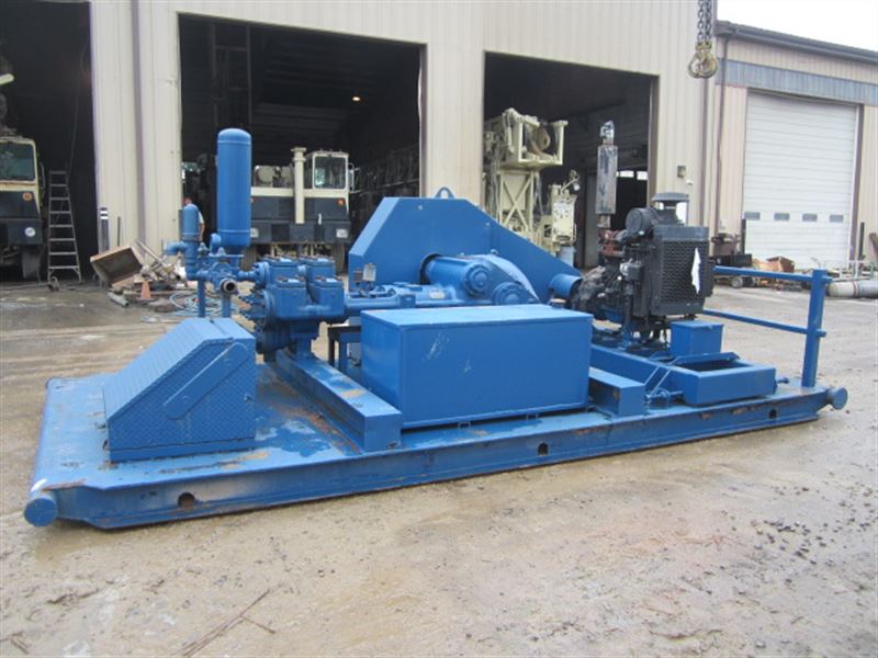
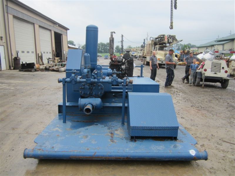
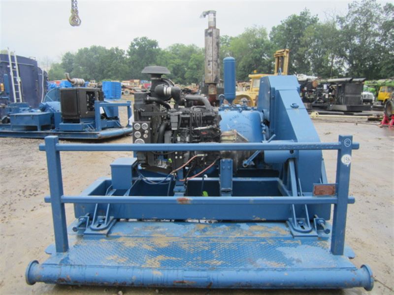
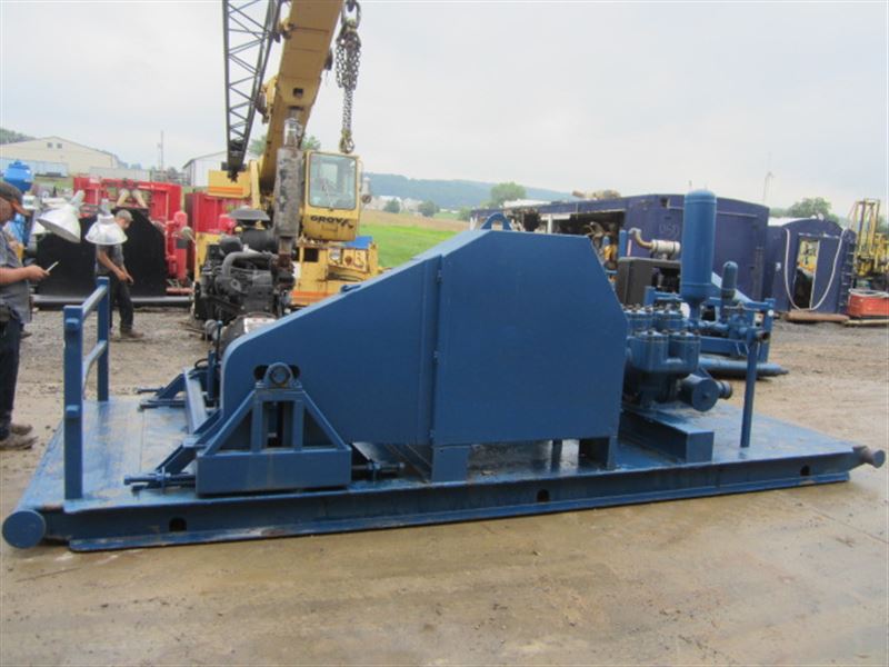
Gaso, 2652, Duplex, Piston Pump (Mud Pump)Pumps in this series 258 horsepower! 12" stroke continuous duty double acting duplex pump2651 Rated at pump speeds up to 85 RPM2652 Maximum discharge pressures up to 1,125 psi Equipped with cast steel fluid end Equipped with internal gear reduction unit
SpecsSpec U.S. StandardType: duplexMinimum Piston Diameter: 4"Maximum Piston Diameter: 7¼"Stroke length: 12"Maximum Working Pressure: 1,125 PSIRod/Piston Load: 22100lbGallons per Minute: 702.0Barrels per Day: 24069Brake Horse Power: 243.6
Performance Data Table English Units 50 RPM 60 RPM 70 RPM 80 RPM 85 RPMPump Plunger Plunger Area BPD per GPM per Max BPD GPM BPD GPM BPD GPM BPD GPM BPD GPM Dia. In. Sq. In. RPM RPM Press. PSI
Bolted Valve and Cylinder head covers Bolted or threaded type glands & removable stuffing boxes File hard steel piston rods Standard valve types For crude oil transfer: Steel wing guided valve & seat For slush / mud service: Steel wing guided with replaceable insert Standard Valve Types: For crude oil transfer: Cast iron piston body, ring type Cast iron, chrome faced, piston rings For slush / mud service: Mission slush type piston w/ replaceable rubbers General service piston rod packingÂÂ
Copyright and Disclaimers WheatleyGaso.com is your resource for Gaso pumps, Gaso pump parts and a supplier of ORIGINAL GASO PARTS and equipment, new used and remanufactured Wheatley, GASO and Wheatley/GASO plunger and piston pumps and pump parts and is not affiliated with Wheatley/GASO Inc. or its parent company, National Oilwell Varco, p Copyright ©2017, IntelleQ Holdings, LLC. All rights reserved, *Used under license from IntelleQ Holdings, LLC.

Rig pump output, normally in volume per stroke, of mud pumps on the rig is one of important figures that we really need to know because we will use pump out put figures to calculate many parameters such as bottom up strokes, wash out depth, tracking drilling fluid, etc. In this post, you will learn how to calculate pump out put for triplex pump and duplex pump in bothOilfield and Metric Unit.
If you run a mud rig, you have probably figured out that the mud pump is the heart of the rig. Without it, drilling stops. Keeping your pump in good shape is key to productivity. There are some tricks I have learned over the years to keeping a pump running well.
First, you need a baseline to know how well your pump is doing. When it’s freshly rebuilt, it will be at the top efficiency. An easy way to establish this efficiency is to pump through an orifice at a known rate with a known fluid. When I rig up, I hook my water truck to my pump and pump through my mixing hopper at idle. My hopper has a ½-inch nozzle in it, so at idle I see about 80 psi on the pump when it’s fresh. Since I’m pumping clear water at a known rate, I do this on every job.
As time goes on and I drill more hole, and the pump wears, I start seeing a decrease in my initial pressure — 75, then 70, then 65, etc. This tells me I better order parts. Funny thing is, I don’t usually notice it when drilling. After all, I am running it a lot faster, and it’s hard to tell the difference in a few gallons a minute until it really goes south. This method has saved me quite a bit on parts over the years. When the swabs wear they start to leak. This bypass pushes mud around the swab, against the liners, greatly accelerating wear. By changing the swab at the first sign of bypass, I am able to get at least three sets of swabs before I have to change liners. This saves money.
Before I figured this out, I would sometimes have to run swabs to complete failure. (I was just a hand then, so it wasn’t my rig.) When I tore the pump down to put in swabs, lo-and-behold, the liners were cut so badly that they had to be changed too. That is false economy. Clean mud helps too. A desander will pay for itself in pump parts quicker than you think, and make a better hole to boot. Pump rods and packing last longer if they are washed and lubricated. In the oilfield, we use a petroleum-based lube, but that it not a good idea in the water well business. I generally use water and dish soap. Sometimes it tends to foam too much, so I add a few tablets of an over the counter, anti-gas product, like Di-Gel or Gas-Ex, to cut the foaming.
Maintenance on the gear end of your pump is important, too. Maintenance is WAY cheaper than repair. The first, and most important, thing is clean oil. On a duplex pump, there is a packing gland called an oil-stop on the gear end of the rod. This is often overlooked because the pump pumps just as well with a bad oil-stop. But as soon as the fluid end packing starts leaking, it pumps mud and abrasive sand into the gear end. This is a recipe for disaster. Eventually, all gear ends start knocking. The driller should notice this, and start planning. A lot of times, a driller will change the oil and go to a higher viscosity oil, thinking this will help cushion the knock. Wrong. Most smaller duplex pumps are splash lubricated. Thicker oil does not splash as well, and actually starves the bearings of lubrication and accelerates wear. I use 85W90 in my pumps. A thicker 90W140 weight wears them out a lot quicker. You can improve the “climbing” ability of the oil with an additive, like Lucas, if you want. That seems to help.
Outside the pump, but still an important part of the system, is the pop-off, or pressure relief valve. When you plug the bit, or your brother-in-law closes the discharge valve on a running pump, something has to give. Without a good, tested pop-off, the part that fails will be hard to fix, expensive and probably hurt somebody. Pop-off valve are easily overlooked. If you pump cement through your rig pump, it should be a standard part of the cleanup procedure. Remove the shear pin and wash through the valve. In the old days, these valves were made to use a common nail as the shear pin, but now nails come in so many grades that they are no longer a reliable tool. Rated shear pins are available for this. In no case should you ever run an Allen wrench! They are hardened steel and will hurt somebody or destroy your pump.
One last thing that helps pump maintenance is a good pulsation dampener. It should be close to the pump discharge, properly sized and drained after every job. Bet you never thought of that one. If your pump discharge goes straight to the standpipe, when you finish the job your standpipe is still full of fluid. Eventually the pulsation dampener will water-log and become useless. This is hard on the gear end of the pump. Open a valve that drains it at the end of every job. It’ll make your pump run smoother and longer.


 8613371530291