
how to install bomco mud pump crosshead supplier
Thanks for using F series mud pumps produced by Baoji Oilfield Machinery Co., Ltd. The outline dimension, frame, and fluid end of F-1300 and 1600 mud pump are the same, only the bearing and gear pair of power end are different. For convenience of customer, this manual introduces these two kinds mud pumps at the same time.
(3.206) Note: 1. Based on 100% volumetric efficiency and 90% mechanical efficiency. Recommended strokes and input power for continuous service. Table 1B Performance data of F-1300/1600 Mud Pump Liner Diameter, in & Rating pressure, MPa(Psi) 6 3/4 6 1/2 6 1/4...
Fig. 2 1.2.1. Ground Installation When ground installation is going on, 8 pieces of 76mm×305mm boards is cushioned in the direction of pump skid, as indicated in Fig.2. The base of boards should be 300mm wider than that of pump skid beam.
Fig. 3 1.2.3. Installations of Driving Device The drive between the mud pumps and prime mover should be adopted V-belts or multi-row chains drive, which is installed with precision to assure longest service life and minimum possibility of unexpected or undesirable shutdowns due to drive failures. When installing the drive sheave or sprocket, make sure all grease or rust preventative is removed clearly from the shaft end and the matched bore.
Stationary spray pipes have been used on F-series pumps Ref. Fig 5. It consists of a fixture frame (1), steel pipe (2) and spray nozzle (3), it makes cooling fluid spray to piston and liner. Adjust cooling water supply to the manifold and inspect spray nozzle operation very often to make sure the nozzle is pointed directly at the piston.
Instruction Manual for F1300/1600 Mud Pump 1.6.2. Liners Installs wear-resisting plate seal (1) in counter bore of fluid end (see Fig. 8). Install wear-resisting plate (2) through studs until it seats against fluid end. Mount liner flange (3) over studs with the starting thread at the 5 o’clock position and tighten bolts with 640~690N.m (470~510ft.lbs) torque.
Instruction Manual for F1300/1600 Mud Pump 1.6.6. Valve Cover Install valve cover seal ring (18) into bore, and after grease the valve cover seal area and threads area, tighten the valve covers into place using a sledge hammer and bar. 1.6.7 Discharge Manifold API 5"...
Instruction Manual for F1300/1600 Mud Pump shield ○ 8 is used for lifting dampener assembly. Before assembly thoroughly clean ring groove, gasket ring ○ 1 and groove of mating flange and coat with grease. Lifting the dampener to the corresponding position of mud pump discharge line, screw nut (R4) with 950~1265N.m (700~935ft.lbs) torque.
Instruction Manual for F1300/1600 Mud Pump Fig.15 (1) Filter (2) Oil distributor (3) Oil line (3A) Spray nozzle (4) Main bearing oil line (4A) Oil distributor (5)Pressure gauge (6) Relief valve (7) Oil trough (8) Oil tube (9) Lubrication pump A pressure relief valve (6) is mounted to the oil distributor (2) to prevent excess pressure from damaging oil pump and drive.
Instruction Manual for F1300/1600 Mud Pump Fig.18 (1) Cover (2) Bolt (3) Retainer ring (4) Bolt (5) Bearing retainer ring (7) Retainer ring (8) Bolt (8A) Inner hex bolts (9) Main bearing (10) Right bearing sleeve (11) Left bearing sleeve (12) Outer retainer ring (13) Connecting rod bearing (14) Inner retainer ring (15) Bolt (16) Main bearing retainer (17) Inner race retainer (18) Bolt (19) Crosshead bearing 1) Install gear ring and check run-out.
Instruction Manual for F1300/1600 Mud Pump valve spring, change the damaged one. Check if the locknuts of piston are corrosive or damaged. Change if they are Weekly damaged (normally, change after using three times). Weekly Check the filter screen of lubricating system. Clean it if it is plugged. Weekly Loosen the plug of drain flange, discharge the dirt and water in the oil pool.
Instruction Manual for F1300/1600 Mud Pump become sealed off and the air gets charging piping or change the discharge reduces or no mud into the pump. gasket. discharged. 2. The suction filter screen is 2. Stop the pump and clean the plugged.
Instruction Manual for F1300/1600 Mud Pump F-1300/1600 Spare Parts List F-1300/1600 Tool List F-1300/1600 Mud Pump General Assembly 11 43 54 6 56 17 8 36 B向...
Instruction Manual for F1300/1600 Mud Pump F-1300/1600 Drilling Mud Pump Drawing No. Item Description F-1300 F-1600 Frame assembly AH1301020100 AH1301020100 Crank shaft assembly AH1301020200 AH1601020100 Pinion shaft assembly AH1301020300 AH1601020200 Crosshead assembly AH1301020400 AH1301020400 Fluid end assembly AH1301020500 AH1301020500 Power...
Instruction Manual for F1300/1600 Mud Pump Drawing No. Item Description F-1300 F-1600 Flange T508-1002 T508-1002 KB-75 Dampener AK75350200 AK75350200 JA-3 Shear relieve valve AH0000060200 AH0000060200 Connection tube T510-1002 T510-1002 Cover plate AH1301011800 AH1301011800 Right-angle joint T511-1002 T511-1002 Bolt 1/2-13UNCX1 T500-1001...
Instruction Manual for F1300/1600 Mud Pump Crankshaft Assembly Fluid End 13 14 Drawing No. Item Description F-1300 F-1600 Main bearing AH130101020100 AH130101020100 cover Bearing sleeve, AH1301010202 AH1601020101 right Gasket AH1301010203 AH1301010203 Inner race AH1301010204 AH1301010204 retainer Outer race AH130101020500 AH160101010200...
Instruction Manual for F1300/1600 Mud Pump Drawing No. Item Description F-1300 F-1600 AH130101020100 AH130101020100 Locating ring (I) AH1301020201 AH1601020101 Hollow crankshaft AH1301010203 AH1301010203 Locating ring (II) AH1301010204 AH1301010204 Gear ring AH130101020500 AH160101010200 Piston 1/2-8UN Bolt 1 1/2-8UNx5 AH1301020202 AH1601020102 AH1301020203...
Instruction Manual for F1300/1600 Mud Pump Drawing No. Item Description F-1300 F-1600 AH1301010218 AH1601010108 Gear ring (split one) 420501036160200000 420501036160200000 Bolt 1 1/2-8UN× F-1300/1600 Pinion Shaft Assembly 11 16 Fluid End Drawing No. Item Description F-1300 F-1600 AH1301020301 AH1301020301 Key 2″×2″×11 3/8″ AH1301020302 AH1601020201...
Instruction Manual for F1300/1600 Mud Pump Drawing No. Item Description F-1300 F-1600 T500-1027 T500-1027 Bolt 7/8-9UNCX2 AH1301010311 AH1301010311 seal 9.125"X10.375"X0.625" AH1301010312 AH1301010312 Bearing 4G32844H 420503011221600000 420503011221600000 Spring washer 22 (GB93) 420503011141600000 420503011141600000 Spring washer 14 (GB93) AH1301010313 AH1301010313 Flange T500-2003...
Instruction Manual for F1300/1600 Mud Pump F-1300/1600 Crosshead Assembly 30 20 Link 2426 Item No. Qty. Description Drawing No. Crosshead AH1301020401 Crosshead guide (upper) AH1301010402 Shim set AH100101041700 Shim AH1301010403 Stuffing box AH1301010404 Sealing ring AH1301010405 O-ring φ190×3.55 (GB3452.1) 530301011900035507...
Instruction Manual for F1300/1600 Mud Pump Item No. Qty. Description Drawing No. Double lip seal 5"X6.25"X0.625" AH1301010406 Locking spring AH1301010407 Mud guard plate AH1301010408 Crosshead extension rod AH1301010409 Crosshead pin AH1301020403 O-ring φ125×7 (GB3452.1) 530301011250070007 Bolt 3/4-10UNCX2 1/2 T500-3010 Plate gasket AH1301010411 O-ring φ160×7 (GB3452.1) 530301011600070007...
Instruction Manual for F1300/1600 Mud Pump Item Qty. Description Drawing No. AH130101052300 Shim set AH1001010527 Gasket 39 AH1001010510 Valve rod guide T500-7002 Stud bolt 1 1/2-8UNCX10 1/2 T501-2001 Nut 1 1/2-8UN AH1001010512 Retainer AH0501020509 Bolt 3/8-16UNCX3/4 530301010412035507 O-ring 41.2x3.55 (GB3452.1) T501-303.0 Piston nut 1 1/2-8UN 530301011850070007...
Instruction Manual for F1300/1600 Mud Pump Item Description Drawing No. Key 3/16×3/16×1 T516-2001 Oil pump gear assembly AH080102060100 90° elbow NPT1/4×NPT 3/8 T001-2204 Bolt A12(GB5650) 520902540320120100 Inner hexagon screw 5/16-18UNCX1 T500-3003 Connector A16 (JB/ZQ4410) 520901010350040040 Connector A8 (JB/ZQ4410) 520901010350050050 90° elbow NPT1/4×NPT1/4 T001-2203 Copper tube 051102010080010002...
Instruction Manual for F1300/1600 Mud Pump Item Description Drawing No. Washer A12 (GB5651) 520902551280120100 Bolt 1/4-20UNCX3/4 T500-1007 Oil jet AH1301010601 Copper tube Φ12×610 (GB1527) 051102010012010002 Copper tube Φ8×813 (GB1527) 051102010080010002 Connector A8 (GB5628.1) 520901010050050050 Pipe clamp-double Φ8 AH050102060200 051102010010010002 Copper tube Φ10×1956 (GB1527)...
Instruction Manual for F1300/1600 Mud Pump AH130102080100 Guard AH130102080300 Sheave AH1301010802 Support Assembly AH100102080200 Connector Z1″-G1″ AH1001010804 Connector Z1″ AH1001010805 Connector G1″-M33×2 AH1001010806 Connector ZG2-1/2″ AH1001010807 Connector ZG2 1/2″-Z2 1/2 AH1001010808 Hose Φ22×Φ37 140501010220100000 Hose connector Φ22×Φ37 AH100101080900 Elbow 90° Z1" AH1001010810 Connection plate AH1001020803...
Instruction Manual for F1300/1600 Mud Pump F-1300/1600 Suction Dampener Item No. Description Drawing No. Suction dampener assembly AH0000050100 Bladder AH0000050101 Cover AH0000050102...
Instruction Manual for F1300/1600 Mud Pump F-1300/1600 Discharge Strainer Assembly Item Description Part No. O-ring φ165×7 530301011650070007 Strainer Assembly AH100101190200 Housing AH1001011901 Stud M39×2-M39×3×135 T503-4007 Nut M39×3 T507-2011 Flange 5 1/8×35MPa T508-1002 Gasket ring R44 T508-5002 Discharge cross joint AH100101200300...
KB-75 Pulsation Dampener Item Description Drawing No. General drawing AK75350200 Gasket ring R39 T508-5001 Bottom plug AK75350101 Bladder AK7535010200 Housing assembly AK7535020100 Cover AK75350202 Tee joint NPT 1/4″ T511-2001 Joint NPT 1/4″ AK75350106 Pressure gauge guard assembly AK7535020300 Air discharge valve AK7535010001 Pressure gauge 0-25MPa NPT1/4 380202052250006020...
Instruction Manual for F1300/1600 Mud Pump Gasket T514-1001 Stud bolt 1 1/2X4 3/4 T500-6002 Nut 1 1/2-8UN T501-2001 Stud nut 1 1/4X4 1/4 T500-6003 Nut 1 1/4-8UN T500-2002 Pulsation Dampener Charging Hose Assembly Item Description Drawing No. Pulsation dampener charging AH100102130100 hose assembly Nut G5/8″...
Instruction Manual for F1300/1600 Mud Pump Screw M4×16 420101021104001600 Bolt T500-1016 3/8-16UNCX4 1/4 T501-1005 3/8-16UNC Screw M3×8 420101020703000800...
Instruction Manual for F1300/1600 Mud Pump F-1300/1600 Tool List Item No. Description Drawing No. Attachment tools AH1301021000 Liner lifting tool AH130102100100 Cylinder head rod AH100101210100 Sleeve 2 3/8″ AH1001012108 Sleeve 2″ AH1001012109 Sleeve 3 5/8″ AH1301011602 Sleeve 1 1/2″ AH1301011603...

This website is using a security service to protect itself from online attacks. The action you just performed triggered the security solution. There are several actions that could trigger this block including submitting a certain word or phrase, a SQL command or malformed data.

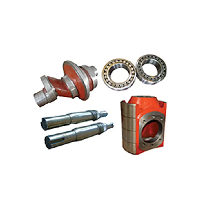
Crosshead: A system which creates linear reciprocating motion derived from the crankshaft’s rotary motion through the connecting rod. The reciprocating motion of the crosshead is applied to the piston via the extension rod.
A crosshead is a mechanism used in large reciprocating engines to eliminate sideways pressure on the piston. The crosshead of mud pump produced by our company is made of high quality wear resistant with special techniques. It features little deformation, higher precision and very little tolerance.
The crosshead is the critical part on the power end of the mud pump. It slides in the upper and lower guide plates, motivating the intermediate draw bar to deliver driving force to the hydraulic end. One of its ends fixes the intermediate draw bar. The cavity connects the small end of the connecting rod through cross head pin.
The material of the crosshead is nodular cast iron with the strength of extension of more than 600MPa, which ensures high intensity and abrasive resistance.
Crosshead has high accuracy and precious dimension and no deformation. Besides F-500 mud pump that is cylindrical structure, upper and lower guide structures are used for other mud pumps, so that the concentricity can be adjusted by adding space under the lower guide. Flange-bolts with pinhole fit are used for connecting crosshead to extension rod.
A: First we discuss order details, production details. Then we issue you an PI for your confirmation. You will be requested to do pr-e paid full payment or deposit before we go into production. After we get the deposit, we start to process the order. We usually need 15-25 days if we don"t have the items in stock. Before production has been finished, we will contact you for shipment details, and the balance payment. After payment has been settled, we start to prepare the shipment for you.

The time depends on the MOQ of the order. The delivery time for parts is generally 1-3 days, and equipment is 7-30 days. In addition, contact us to get the full time of the order.

A wide variety of bomco f1000 mud pump options are available to you, such as 1 year, not available.You can also choose from new, bomco f1000 mud pump,As well as from energy & mining, construction works , and machinery repair shops. and whether bomco f1000 mud pump is 1.5 years, 6 months, or unavailable.

1,.Crosshead is the significant parts of the power end system for drilling mud pump, the pump transmit power to the fluid end system through the cross head assembly.
Xi"an Kingwell Oilfield Machinery Co.,Ltd is a professional supplier for oilfield products according to the API standard. Our products have exported to USA, Canada, Australia, Egypt, India and Uae, etc with high quality and short supply and good service, our products have got good reputation home and abroad .
Equipped with latest machining facilities. Our company could meet long term production target and be governed efficiently by well-qualified and experienced Board of Directors and Engineers.
We have a team of well qualified and experienced field support personnel for Training. According to customer"s requirements, we provide operation training service for our customers who cooperated with us.
We believe in Customer delight, achieved by the supply of Quality Products & Services and Continual Improvement in our Manufacturing Processes for timely delivery at competitive prices. We work in a professional, competitive, and cost-effective manner consistent with the Customer requirement
Any interest of above products or relative parts, PLS feel free contact back, and we will offer a good price and show you our best service upon received from you.

Mud pump is one of the most important equipments in the drilling operation which discharge high viscosity,heavy density and low sand contented fluid to well bottom in order to cool drill bit,flush well ,crush the rock and take out debris.
Mud pump is designed and manufactured in compliance with API Speck 7K"Specification for Drilling Equipment".All wearing parts of fluid end(valve,valve seat,liner and ect) can be interchanged acc to API specification.

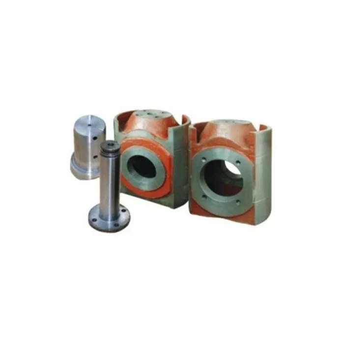
Hydraulic cylinder is forged of alloy steel. Three cylinders of one pump are interchangeable with each other. According to customers’ special requirements, to enhance the anti-corrosion performance, the surface of the hydraulic cylinder is supposed to be processed with chemical plating nickel. Pulsation dampener, shear relief valve and discharge strainer are separately mounted on the outlet.
This system is consisted of spray pump, cooling water tank and spray pipelines with the function of the necessary cooling and splashing to liners and pistons to prolong their lifetime.
The splashing pump is the centrifugal pump which can be driven by the belt mounted on the end of input shaft, or can be individually driven by a motor with water as the cooling and lubrication media.
The combination of forced lubrication and splashing lubrication is used for the power end. For the purpose of forced lubrication, the gear oil pump located at the oil tank feeds compressed oil to crossheads, extension rods and bearings respectively via the lubrication pipe lines. More ever, the operation situation of the gear oil pump can be observed by the manometer embedded in the after body of mud pumps.
This website is using a security service to protect itself from online attacks. The action you just performed triggered the security solution. There are several actions that could trigger this block including submitting a certain word or phrase, a SQL command or malformed data.
2.Any unusual conditions of the cooling system should be avoided. Such as: if spray pump packing leaks; if spray pipe is bent or blocked; if water stream of spray nozzle sprays to 12 o’clock direction of the top of ceramic liner inner surface; if water flow is adequate, etc. If there is any unusual conditions, examination and maintenance should be carried out without delay.
2) Loosen threaded ring by 1-2 threads, use pipe tongs to bite top end of liner and rotate liner (if it’s hard to rotate, please add a torsion bar to the handle of pipe tongs), then fasten threaded ring.
6.Mud should be released out from mud pump when drilling job finished in winter and the temperature is lower than 0 centigrade degrees. And before restart the pump, the ice from liner and piston surface need to be cleaned in case the ice will scratch the liner and piston working surface.
7.Frequently check guide plate, pony rod, piston rod, cross head, piston and clamp, if there is any rusting or deformed,needed to be changed or repaired in time. And please be noted that the piston definitely cannot be eccentric or eccentric wear.
As a reminder: the outer diameter of piston core is 1.8 - 2.2mm smaller than that of the ceramic liner inner diameter. Meanwhile, the piston core end is designed to be in inverted arc angle to reduce the resistance of cooling water.

A mud pump (sometimes referred to as a mud drilling pump or drilling mud pump), is a reciprocating piston/plunger pump designed to circulate drilling fluid under high pressure (up to 7,500 psi or 52,000 kPa) down the drill string and back up the annulus. A mud pump is an important part of the equipment used for oil well drilling.
Mud pumps can be divided into single-acting pump and double-acting pump according to the completion times of the suction and drainage acting in one cycle of the piston"s reciprocating motion.
Mud pumps come in a variety of sizes and configurations but for the typical petroleum drilling rig, the triplex (three piston/plunger) mud pump is used. Duplex mud pumps (two piston/plungers) have generally been replaced by the triplex pump, but are still common in developing countries. Two later developments are the hex pump with six vertical pistons/plungers, and various quintuplexes with five horizontal piston/plungers. The advantages that these new pumps have over convention triplex pumps is a lower mud noise which assists with better measurement while drilling (MWD) and logging while drilling (LWD) decoding.
The fluid end produces the pumping process with valves, pistons, and liners. Because these components are high-wear items, modern pumps are designed to allow quick replacement of these parts.
To reduce severe vibration caused by the pumping process, these pumps incorporate both a suction and discharge pulsation dampener. These are connected to the inlet and outlet of the fluid end.
The power end converts the rotation of the drive shaft to the reciprocating motion of the pistons. In most cases a crosshead crank gear is used for this.
Displacement is calculated as discharged liters per minute. It is related to the drilling hole diameter and the return speed of drilling fluid from the bottom of the hole, i.e. the larger the diameter of drilling hole, the larger the desired displacement. The return speed of drilling fluid should wash away the debris and rock powder cut by the drill from the bottom of the hole in a timely manner, and reliably carry them to the earth"s surface. When drilling geological core, the speed is generally in range of 0.4 to 1.0 m^3/min.
The pressure of the pump depends on the depth of the drilling hole, the resistance of flushing fluid (drilling fluid) through the channel, as well as the nature of the conveying drilling fluid. The deeper the drilling hole and the greater the pipeline resistance, the higher the pressure needed.
With the changes of drilling hole diameter and depth, the displacement of the pump can be adjusted accordingly. In the mud pump mechanism, the gearbox or hydraulic motor is equipped to adjust its speed and displacement. In order to accurately measure the changes in pressure and displacement, a flow meter and pressure gauge are installed in the mud pump.
The construction department should have a special maintenance worker that is responsible for the maintenance and repair of the machine. Mud pumps and other mechanical equipment should be inspected and maintained on a scheduled and timely basis to find and address problems ahead of time, in order to avoid unscheduled shutdown. The worker should attend to the size of the sediment particles; if large particles are found, the mud pump parts should be checked frequently for wear, to see if they need to be repaired or replaced. The wearing parts for mud pumps include pump casing, bearings, impeller, piston, liner, etc. Advanced anti-wear measures should be adopted to increase the service life of the wearing parts, which can reduce the investment cost of the project, and improve production efficiency. At the same time, wearing parts and other mud pump parts should be repaired rather than replaced when possible.

We specialize in complete Bomco restoration of internal wear parts Offering thermal spray coatings and specialty welding processes OD & IS Grinding & Machining To OEM Size.
Periodically we"ll inspect for wear, cracks and damage to critical components such as bearings, bull gear and pinion, conrods and crossheads. We"ll check the condition of your seals and other rubber goods and look for oil contamination. We"ll inspect your frame and ensure your pump is set up as per the manufacturer"s recommended tolerances, providing feedback and detailed reporting.
Bomco parts including the fluid end, power end, stuffing boxes, plungers, seals, bearings, diesel engines, and natural gas engines. We also have blasting and painting facilities as well as a machine shop. We have many years of experience rebuilding mud pumps
Where Bomco overhaul is required we"ll take care of complete disassembly, cleaning and NDT. Repairs will be made to machined components as necessary. Bearings, seals and other components will be replaced in line with our inspections. Motors will be overhauled, lube systems serviced and pulsation dampeners recertified. We"ll also check your fluid ends are in spec and can repair or replace. Your pump is then fully reassembled and commissioned.

This website is using a security service to protect itself from online attacks. The action you just performed triggered the security solution. There are several actions that could trigger this block including submitting a certain word or phrase, a SQL command or malformed data.


 8613371530291