
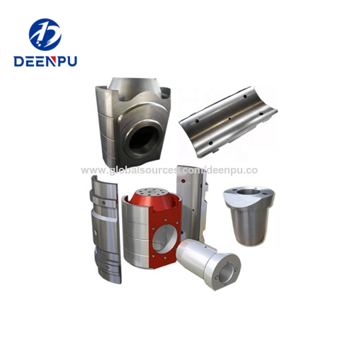
how to install bomco mud pump crosshead in stock

Thanks for using F series mud pumps produced by Baoji Oilfield Machinery Co., Ltd. The outline dimension, frame, and fluid end of F-1300 and 1600 mud pump are the same, only the bearing and gear pair of power end are different. For convenience of customer, this manual introduces these two kinds mud pumps at the same time.
(3.206) Note: 1. Based on 100% volumetric efficiency and 90% mechanical efficiency. Recommended strokes and input power for continuous service. Table 1B Performance data of F-1300/1600 Mud Pump Liner Diameter, in & Rating pressure, MPa(Psi) 6 3/4 6 1/2 6 1/4...
Fig. 2 1.2.1. Ground Installation When ground installation is going on, 8 pieces of 76mm×305mm boards is cushioned in the direction of pump skid, as indicated in Fig.2. The base of boards should be 300mm wider than that of pump skid beam.
Fig. 3 1.2.3. Installations of Driving Device The drive between the mud pumps and prime mover should be adopted V-belts or multi-row chains drive, which is installed with precision to assure longest service life and minimum possibility of unexpected or undesirable shutdowns due to drive failures. When installing the drive sheave or sprocket, make sure all grease or rust preventative is removed clearly from the shaft end and the matched bore.
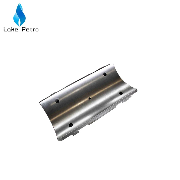
Stationary spray pipes have been used on F-series pumps Ref. Fig 5. It consists of a fixture frame (1), steel pipe (2) and spray nozzle (3), it makes cooling fluid spray to piston and liner. Adjust cooling water supply to the manifold and inspect spray nozzle operation very often to make sure the nozzle is pointed directly at the piston.
Instruction Manual for F1300/1600 Mud Pump 1.6.2. Liners Installs wear-resisting plate seal (1) in counter bore of fluid end (see Fig. 8). Install wear-resisting plate (2) through studs until it seats against fluid end. Mount liner flange (3) over studs with the starting thread at the 5 o’clock position and tighten bolts with 640~690N.m (470~510ft.lbs) torque.
Instruction Manual for F1300/1600 Mud Pump 1.6.6. Valve Cover Install valve cover seal ring (18) into bore, and after grease the valve cover seal area and threads area, tighten the valve covers into place using a sledge hammer and bar. 1.6.7 Discharge Manifold API 5"...
Instruction Manual for F1300/1600 Mud Pump shield ○ 8 is used for lifting dampener assembly. Before assembly thoroughly clean ring groove, gasket ring ○ 1 and groove of mating flange and coat with grease. Lifting the dampener to the corresponding position of mud pump discharge line, screw nut (R4) with 950~1265N.m (700~935ft.lbs) torque.
Instruction Manual for F1300/1600 Mud Pump Fig.15 (1) Filter (2) Oil distributor (3) Oil line (3A) Spray nozzle (4) Main bearing oil line (4A) Oil distributor (5)Pressure gauge (6) Relief valve (7) Oil trough (8) Oil tube (9) Lubrication pump A pressure relief valve (6) is mounted to the oil distributor (2) to prevent excess pressure from damaging oil pump and drive.
Instruction Manual for F1300/1600 Mud Pump Fig.18 (1) Cover (2) Bolt (3) Retainer ring (4) Bolt (5) Bearing retainer ring (7) Retainer ring (8) Bolt (8A) Inner hex bolts (9) Main bearing (10) Right bearing sleeve (11) Left bearing sleeve (12) Outer retainer ring (13) Connecting rod bearing (14) Inner retainer ring (15) Bolt (16) Main bearing retainer (17) Inner race retainer (18) Bolt (19) Crosshead bearing 1) Install gear ring and check run-out.
Instruction Manual for F1300/1600 Mud Pump valve spring, change the damaged one. Check if the locknuts of piston are corrosive or damaged. Change if they are Weekly damaged (normally, change after using three times). Weekly Check the filter screen of lubricating system. Clean it if it is plugged. Weekly Loosen the plug of drain flange, discharge the dirt and water in the oil pool.
Instruction Manual for F1300/1600 Mud Pump become sealed off and the air gets charging piping or change the discharge reduces or no mud into the pump. gasket. discharged. 2. The suction filter screen is 2. Stop the pump and clean the plugged.
Instruction Manual for F1300/1600 Mud Pump F-1300/1600 Spare Parts List F-1300/1600 Tool List F-1300/1600 Mud Pump General Assembly 11 43 54 6 56 17 8 36 B向...
Instruction Manual for F1300/1600 Mud Pump F-1300/1600 Drilling Mud Pump Drawing No. Item Description F-1300 F-1600 Frame assembly AH1301020100 AH1301020100 Crank shaft assembly AH1301020200 AH1601020100 Pinion shaft assembly AH1301020300 AH1601020200 Crosshead assembly AH1301020400 AH1301020400 Fluid end assembly AH1301020500 AH1301020500 Power...
Instruction Manual for F1300/1600 Mud Pump Drawing No. Item Description F-1300 F-1600 Flange T508-1002 T508-1002 KB-75 Dampener AK75350200 AK75350200 JA-3 Shear relieve valve AH0000060200 AH0000060200 Connection tube T510-1002 T510-1002 Cover plate AH1301011800 AH1301011800 Right-angle joint T511-1002 T511-1002 Bolt 1/2-13UNCX1 T500-1001...
Instruction Manual for F1300/1600 Mud Pump Crankshaft Assembly Fluid End 13 14 Drawing No. Item Description F-1300 F-1600 Main bearing AH130101020100 AH130101020100 cover Bearing sleeve, AH1301010202 AH1601020101 right Gasket AH1301010203 AH1301010203 Inner race AH1301010204 AH1301010204 retainer Outer race AH130101020500 AH160101010200...
Instruction Manual for F1300/1600 Mud Pump Drawing No. Item Description F-1300 F-1600 AH130101020100 AH130101020100 Locating ring (I) AH1301020201 AH1601020101 Hollow crankshaft AH1301010203 AH1301010203 Locating ring (II) AH1301010204 AH1301010204 Gear ring AH130101020500 AH160101010200 Piston 1/2-8UN Bolt 1 1/2-8UNx5 AH1301020202 AH1601020102 AH1301020203...
Instruction Manual for F1300/1600 Mud Pump Drawing No. Item Description F-1300 F-1600 AH1301010218 AH1601010108 Gear ring (split one) 420501036160200000 420501036160200000 Bolt 1 1/2-8UN× F-1300/1600 Pinion Shaft Assembly 11 16 Fluid End Drawing No. Item Description F-1300 F-1600 AH1301020301 AH1301020301 Key 2″×2″×11 3/8″ AH1301020302 AH1601020201...
Instruction Manual for F1300/1600 Mud Pump Drawing No. Item Description F-1300 F-1600 T500-1027 T500-1027 Bolt 7/8-9UNCX2 AH1301010311 AH1301010311 seal 9.125"X10.375"X0.625" AH1301010312 AH1301010312 Bearing 4G32844H 420503011221600000 420503011221600000 Spring washer 22 (GB93) 420503011141600000 420503011141600000 Spring washer 14 (GB93) AH1301010313 AH1301010313 Flange T500-2003...
Instruction Manual for F1300/1600 Mud Pump F-1300/1600 Crosshead Assembly 30 20 Link 2426 Item No. Qty. Description Drawing No. Crosshead AH1301020401 Crosshead guide (upper) AH1301010402 Shim set AH100101041700 Shim AH1301010403 Stuffing box AH1301010404 Sealing ring AH1301010405 O-ring φ190×3.55 (GB3452.1) 530301011900035507...
Instruction Manual for F1300/1600 Mud Pump Item No. Qty. Description Drawing No. Double lip seal 5"X6.25"X0.625" AH1301010406 Locking spring AH1301010407 Mud guard plate AH1301010408 Crosshead extension rod AH1301010409 Crosshead pin AH1301020403 O-ring φ125×7 (GB3452.1) 530301011250070007 Bolt 3/4-10UNCX2 1/2 T500-3010 Plate gasket AH1301010411 O-ring φ160×7 (GB3452.1) 530301011600070007...
Instruction Manual for F1300/1600 Mud Pump Item Qty. Description Drawing No. AH130101052300 Shim set AH1001010527 Gasket 39 AH1001010510 Valve rod guide T500-7002 Stud bolt 1 1/2-8UNCX10 1/2 T501-2001 Nut 1 1/2-8UN AH1001010512 Retainer AH0501020509 Bolt 3/8-16UNCX3/4 530301010412035507 O-ring 41.2x3.55 (GB3452.1) T501-303.0 Piston nut 1 1/2-8UN 530301011850070007...
Instruction Manual for F1300/1600 Mud Pump Item Description Drawing No. Key 3/16×3/16×1 T516-2001 Oil pump gear assembly AH080102060100 90° elbow NPT1/4×NPT 3/8 T001-2204 Bolt A12(GB5650) 520902540320120100 Inner hexagon screw 5/16-18UNCX1 T500-3003 Connector A16 (JB/ZQ4410) 520901010350040040 Connector A8 (JB/ZQ4410) 520901010350050050 90° elbow NPT1/4×NPT1/4 T001-2203 Copper tube 051102010080010002...
Instruction Manual for F1300/1600 Mud Pump Item Description Drawing No. Washer A12 (GB5651) 520902551280120100 Bolt 1/4-20UNCX3/4 T500-1007 Oil jet AH1301010601 Copper tube Φ12×610 (GB1527) 051102010012010002 Copper tube Φ8×813 (GB1527) 051102010080010002 Connector A8 (GB5628.1) 520901010050050050 Pipe clamp-double Φ8 AH050102060200 051102010010010002 Copper tube Φ10×1956 (GB1527)...
Instruction Manual for F1300/1600 Mud Pump AH130102080100 Guard AH130102080300 Sheave AH1301010802 Support Assembly AH100102080200 Connector Z1″-G1″ AH1001010804 Connector Z1″ AH1001010805 Connector G1″-M33×2 AH1001010806 Connector ZG2-1/2″ AH1001010807 Connector ZG2 1/2″-Z2 1/2 AH1001010808 Hose Φ22×Φ37 140501010220100000 Hose connector Φ22×Φ37 AH100101080900 Elbow 90° Z1" AH1001010810 Connection plate AH1001020803...
Instruction Manual for F1300/1600 Mud Pump F-1300/1600 Suction Dampener Item No. Description Drawing No. Suction dampener assembly AH0000050100 Bladder AH0000050101 Cover AH0000050102...
Instruction Manual for F1300/1600 Mud Pump F-1300/1600 Discharge Strainer Assembly Item Description Part No. O-ring φ165×7 530301011650070007 Strainer Assembly AH100101190200 Housing AH1001011901 Stud M39×2-M39×3×135 T503-4007 Nut M39×3 T507-2011 Flange 5 1/8×35MPa T508-1002 Gasket ring R44 T508-5002 Discharge cross joint AH100101200300...
KB-75 Pulsation Dampener Item Description Drawing No. General drawing AK75350200 Gasket ring R39 T508-5001 Bottom plug AK75350101 Bladder AK7535010200 Housing assembly AK7535020100 Cover AK75350202 Tee joint NPT 1/4″ T511-2001 Joint NPT 1/4″ AK75350106 Pressure gauge guard assembly AK7535020300 Air discharge valve AK7535010001 Pressure gauge 0-25MPa NPT1/4 380202052250006020...
Instruction Manual for F1300/1600 Mud Pump Gasket T514-1001 Stud bolt 1 1/2X4 3/4 T500-6002 Nut 1 1/2-8UN T501-2001 Stud nut 1 1/4X4 1/4 T500-6003 Nut 1 1/4-8UN T500-2002 Pulsation Dampener Charging Hose Assembly Item Description Drawing No. Pulsation dampener charging AH100102130100 hose assembly Nut G5/8″...
Instruction Manual for F1300/1600 Mud Pump Screw M4×16 420101021104001600 Bolt T500-1016 3/8-16UNCX4 1/4 T501-1005 3/8-16UNC Screw M3×8 420101020703000800...
Instruction Manual for F1300/1600 Mud Pump F-1300/1600 Tool List Item No. Description Drawing No. Attachment tools AH1301021000 Liner lifting tool AH130102100100 Cylinder head rod AH100101210100 Sleeve 2 3/8″ AH1001012108 Sleeve 2″ AH1001012109 Sleeve 3 5/8″ AH1301011602 Sleeve 1 1/2″ AH1301011603...

Crosshead: A system which creates linear reciprocating motion derived from the crankshaft’s rotary motion through the connecting rod. The reciprocating motion of the crosshead is applied to the piston via the extension rod.
A crosshead is a mechanism used in large reciprocating engines to eliminate sideways pressure on the piston. The crosshead of mud pump produced by our company is made of high quality wear resistant with special techniques. It features little deformation, higher precision and very little tolerance.
The crosshead is the critical part on the power end of the mud pump. It slides in the upper and lower guide plates, motivating the intermediate draw bar to deliver driving force to the hydraulic end. One of its ends fixes the intermediate draw bar. The cavity connects the small end of the connecting rod through cross head pin.
The material of the crosshead is nodular cast iron with the strength of extension of more than 600MPa, which ensures high intensity and abrasive resistance.
Crosshead has high accuracy and precious dimension and no deformation. Besides F-500 mud pump that is cylindrical structure, upper and lower guide structures are used for other mud pumps, so that the concentricity can be adjusted by adding space under the lower guide. Flange-bolts with pinhole fit are used for connecting crosshead to extension rod.
A: First we discuss order details, production details. Then we issue you an PI for your confirmation. You will be requested to do pr-e paid full payment or deposit before we go into production. After we get the deposit, we start to process the order. We usually need 15-25 days if we don"t have the items in stock. Before production has been finished, we will contact you for shipment details, and the balance payment. After payment has been settled, we start to prepare the shipment for you.

This website is using a security service to protect itself from online attacks. The action you just performed triggered the security solution. There are several actions that could trigger this block including submitting a certain word or phrase, a SQL command or malformed data.

This website is using a security service to protect itself from online attacks. The action you just performed triggered the security solution. There are several actions that could trigger this block including submitting a certain word or phrase, a SQL command or malformed data.

We specialize in complete Bomco restoration of internal wear parts Offering thermal spray coatings and specialty welding processes OD & IS Grinding & Machining To OEM Size.
Periodically we"ll inspect for wear, cracks and damage to critical components such as bearings, bull gear and pinion, conrods and crossheads. We"ll check the condition of your seals and other rubber goods and look for oil contamination. We"ll inspect your frame and ensure your pump is set up as per the manufacturer"s recommended tolerances, providing feedback and detailed reporting.
Bomco parts including the fluid end, power end, stuffing boxes, plungers, seals, bearings, diesel engines, and natural gas engines. We also have blasting and painting facilities as well as a machine shop. We have many years of experience rebuilding mud pumps
Where Bomco overhaul is required we"ll take care of complete disassembly, cleaning and NDT. Repairs will be made to machined components as necessary. Bearings, seals and other components will be replaced in line with our inspections. Motors will be overhauled, lube systems serviced and pulsation dampeners recertified. We"ll also check your fluid ends are in spec and can repair or replace. Your pump is then fully reassembled and commissioned.

A mud pump (sometimes referred to as a mud drilling pump or drilling mud pump), is a reciprocating piston/plunger pump designed to circulate drilling fluid under high pressure (up to 7,500 psi or 52,000 kPa) down the drill string and back up the annulus. A mud pump is an important part of the equipment used for oil well drilling and manufactured according to API specification 7K.
The advantages of the drilling mud pump include the ability to move high-solids-content fluids laden with abrasives, the ability to pump large particles, ease of operation and maintenance, reliability, and the ability to operate over a wide range of pressures and flow rates by changing the diameter of pump liners and pistons.
The fluid end includes cylinders (module), valve assembly, cylinder liners, piston assembly, suction manifold, discharge manifold, piston rod, pulsation dampener assembly, etc.
As an important equipment for oilfield drilling operation, a drilling mud pump delivers circulating high-pressure drilling fluid or drilling mud to the bottom of the oil well, flushes the bottom of the well, breaks the rock, cools, lubricates and clean the drill bit, and carries the cuttings back to the ground.
The drilling mud is also used to suspend and carry out drill cuttings from the drill bits as it is brought in and out of the hole. This ensures that the drill bit does not clog and overheat, and makes the entire drilling operation smooth and safe.
Rotational power is supplied to the mud pump through an external power source like a diesel engine or electric motor. The power end of the mud pump converts the rotational energy through a crankshaft to a reciprocating motion of pistons.
The pistons move back and forth in mud pump liners, exerting a force on the cylinder chamber. During the retraction of the piston, valves open to allow the fluid to be drawn into the cylinder. Once the piston has fully retracted, it is pushed back into the cylinder.
At this time the intake valves are closed and the exhaust valves open, allowing the piston to force the fluid out of the cylinder under pressure. Once the piston reaches its maximum depth into the cylinder, the exhaust valves close and the process repeats.
For Fluid End: piston rod clamp, piston rod, piston assembly, cylinder cover, liner, liner flange, wear plate, cylinder, valve assembly, valve cover, valve guide, flashboard assy., cylinder cover flange, cylinder head, gaskets, studs, nuts, seal rings, pulsation dampener, bladder, discharge manifold, suction manifold, etc.

Product&Reapir: Crown block(TC225 TC250 TC315 TC450 TC585), Travelling block(YC225 YC250 YC315 YC350 YC450 YC450S YC585), Hook(DG225 DG250 DG315 DG350 DG450 DG585 DG675), Rotary table(ZP175 ZP205 ZP275 ZP375 ZP975AS ZP495), Swivel(SL225 SL250 SL450 SL585), Drawworks(JC20 JC30 JC40 JC50 JC70B JC90DB), Mud pump (F-500 F-800 F-1000 F-1300 F-1600 F-1600HL F-2200 F-2200HL 3NB500C,3NB1000C 3NB1300C 3NB1600 SL3NB-1000 SL3NB-1300A SL3NB-1600A),BOP(FH,FZ,Cameron,Shaffer), Control System for Surface Mounted BOP Stacks(FKQ,FKDQ),Disc brake (PS,PSZ, DBS), Bladder accumulator (NXQ), Drilling rig(ZJ40/2250DZ ZJ50/3150DZ ZJ70/4500DZ ZJ90/6750DZ), Workover rig (XJ40,XJ60, XJ80,XJ100,XJ12,ZJ15,ZJ20,ZJ3,XJ350, XJ450, XJ550,XJ650,XJ750), BPM Top drive((DQ120BSC, DQ90BSD, DQ90BSC, DQ80BSC, DQ70BSD, DQ70BSE, DQ70BSC, DQ50BC, DQ40BC, DQ40BSG, DQ40BCQ, DQ40YR, DQ30Y) Make: Bomco, Lanzhou LS,LSPE, SJ Petro, RG Petro, Sichuan Honghua, CPTDC, Beijing BPM, Shanghai Shenkai, Kingdream, CCDC, SJS Serva, DFXK, LS-NOV, Beijing PSK, Gold basin, Renqiu Boke,Guangdong Dongsu.(Guangshi), XBSY.,Tiehu, Rongsheng (HBRS), TSC. Replacements:Mission magnum/Halco centrifugal pump, Cameron FC gate valve,Cameron R check valve, Demco mud valveE( 3K&5K ), Demco butterfly valve,BJ varco handling tools (SDXL, SDML, SDS,DCS,SSC,SSD,YT, HYC, LYT, MP,MYT, MG, RGG, HGG, MGG, TA, SJ), MI SWACO / Mongoose / Derrick / /Brandt / King cobra shale shaker screen (FLC2000,FLC503,Derrick 626), M/D & OTECO Gauge(Type F,Type D,Model 6,Model 7,Model 8), Twin disc,WPT, Eaton clutch & friction disc, National (10-P-130,12-P-160 ,14-P-220 ,8-P-80 ,9-P-100), Gardner denver (PZ-7,PZ-8,PZ-9,PZ-10,PZ-11), EMSCO FB1600.International Brand: Moog, CCS, ATOS, Rexroth, Eaton, Flowrox, Italvibras, Martin, Norgren, Parker, Siemens, Vickers, 3M.Standard:API Spec 4F, API Spec 6A,API Spec 6D,API Spec 600, API Spec 7K, API Spec 8A, API Spec 8C,API Spec 16A, API Spec 16C, API Spec 16D

1,.Crosshead is the significant parts of the power end system for drilling mud pump, the pump transmit power to the fluid end system through the cross head assembly.
Xi"an Kingwell Oilfield Machinery Co.,Ltd is a professional supplier for oilfield products according to the API standard. Our products have exported to USA, Canada, Australia, Egypt, India and Uae, etc with high quality and short supply and good service, our products have got good reputation home and abroad .
Equipped with latest machining facilities. Our company could meet long term production target and be governed efficiently by well-qualified and experienced Board of Directors and Engineers.
We have a team of well qualified and experienced field support personnel for Training. According to customer"s requirements, we provide operation training service for our customers who cooperated with us.
We believe in Customer delight, achieved by the supply of Quality Products & Services and Continual Improvement in our Manufacturing Processes for timely delivery at competitive prices. We work in a professional, competitive, and cost-effective manner consistent with the Customer requirement
Any interest of above products or relative parts, PLS feel free contact back, and we will offer a good price and show you our best service upon received from you.

A mud pump (sometimes referred to as a mud drilling pump or drilling mud pump), is a reciprocating piston/plunger pump designed to circulate drilling fluid under high pressure (up to 7,500 psi or 52,000 kPa) down the drill string and back up the annulus. A mud pump is an important part of the equipment used for oil well drilling.
Mud pumps can be divided into single-acting pump and double-acting pump according to the completion times of the suction and drainage acting in one cycle of the piston"s reciprocating motion.
Mud pumps come in a variety of sizes and configurations but for the typical petroleum drilling rig, the triplex (three piston/plunger) mud pump is used. Duplex mud pumps (two piston/plungers) have generally been replaced by the triplex pump, but are still common in developing countries. Two later developments are the hex pump with six vertical pistons/plungers, and various quintuplexes with five horizontal piston/plungers. The advantages that these new pumps have over convention triplex pumps is a lower mud noise which assists with better measurement while drilling (MWD) and logging while drilling (LWD) decoding.
The fluid end produces the pumping process with valves, pistons, and liners. Because these components are high-wear items, modern pumps are designed to allow quick replacement of these parts.
To reduce severe vibration caused by the pumping process, these pumps incorporate both a suction and discharge pulsation dampener. These are connected to the inlet and outlet of the fluid end.
The power end converts the rotation of the drive shaft to the reciprocating motion of the pistons. In most cases a crosshead crank gear is used for this.
Displacement is calculated as discharged liters per minute. It is related to the drilling hole diameter and the return speed of drilling fluid from the bottom of the hole, i.e. the larger the diameter of drilling hole, the larger the desired displacement. The return speed of drilling fluid should wash away the debris and rock powder cut by the drill from the bottom of the hole in a timely manner, and reliably carry them to the earth"s surface. When drilling geological core, the speed is generally in range of 0.4 to 1.0 m^3/min.
The pressure of the pump depends on the depth of the drilling hole, the resistance of flushing fluid (drilling fluid) through the channel, as well as the nature of the conveying drilling fluid. The deeper the drilling hole and the greater the pipeline resistance, the higher the pressure needed.
With the changes of drilling hole diameter and depth, the displacement of the pump can be adjusted accordingly. In the mud pump mechanism, the gearbox or hydraulic motor is equipped to adjust its speed and displacement. In order to accurately measure the changes in pressure and displacement, a flow meter and pressure gauge are installed in the mud pump.
The construction department should have a special maintenance worker that is responsible for the maintenance and repair of the machine. Mud pumps and other mechanical equipment should be inspected and maintained on a scheduled and timely basis to find and address problems ahead of time, in order to avoid unscheduled shutdown. The worker should attend to the size of the sediment particles; if large particles are found, the mud pump parts should be checked frequently for wear, to see if they need to be repaired or replaced. The wearing parts for mud pumps include pump casing, bearings, impeller, piston, liner, etc. Advanced anti-wear measures should be adopted to increase the service life of the wearing parts, which can reduce the investment cost of the project, and improve production efficiency. At the same time, wearing parts and other mud pump parts should be repaired rather than replaced when possible.
Mud Pumps - Emsco/Bomco 1600 Mud Pump, Unitized 1600 Mud Pump Powered by Two GE 752 Motors Charging Pump, Liner Flush Pump, Relief Valve, Mud Gauge, Etc. ....Call For Price More Info
CONTENTS1. Overview 2. Technical Specifications 3. Flow Rate vs. Pressure 4. Features of Main Components 5. Assembly and Disassembly of Main Components 6. Assembly, Startup and Running Monitoring of Drilling Pump 7. Maintenance 8. Troubleshooting 9. Notes for Storage 10. Special Lubrication Oil and Grease 11. List of Supplied Special Tools 12. Recommended Order List 13. List of LGF-1000 Drilling Pump Drawings 14. List of Spare Parts
1. OverviewLGF-1000 drilling pump is a kind of horizontal triplex single-acting piston pump, made up of power end and fluid end, designed with advanced structure, small size, reliable operation mechanism, exchangeable components, and easy maintenance. The consumables, bearings, sealing parts and technical parameters of this pump are the same as those of F-1000 pump. The power end includes framework, pinion shaft assembly, crank shaft assembly, crosshead assembly and pony rod, etc. The fluid end includes module, valve assembly, liner, piston assembly, suction manifold, etc. In order to avoid gas lock and reduce the pressure pulsation at the discharge outlet, a suction pulsation dampener and a discharge pulsation dampener are installed respectively at the suction pipe and the pump outlet. And a shear-pin safety valve is installed at the other end of the pump outlet to ensure the pump pressure not to exceed the rated working pressure. Splash lubrication and forced lubrication are combined for the gears, bearings and crosshead at the power end to ensure sufficient lubrication, while the water supplied by spray pump is used to lubricate, clean and cool the liner and piston at the fluid end. A special set of handling (assembly and disassembly) tools are provided for routine maintenance of the drilling pump. When LGF-1000 drilling pump remains in good condition it will be an excellent partner of every drilling worker and bring you great benefits.
2. Technical SpecificationsNo. 1 Description Type Parameters Horizontal, pump 2 3 4 5 6 7 8 9 Rated input power (HP) Rated strokes Stroke length Gear type Gear ratio Suction connection size Discharge connection size Pinion shaft diameter 735KW(1000HP) 140 254 mm (10in.) Herringbone tooth 4.207:1(122:29) 12 flange 5-1/8flange 5000#API and 196.85/7-3/4 336.55/13-1/4 triplex single-acting piston
extension (mm/in.) 10 11 12 Key connection size (mm/in.) Module Dimensions mm in. 13 14 Base width (mm/in.) Pump weight (kg/lb) 50.850.8 / 22 API 6#142.875/5-5/8 426931671818 168124-5/871-1/16 1790/70 1/2 18790/41420
4. Features of Main ComponentsLGF-1000 pump consists of 2 parts, power end and fluid end. The power end is used to provide adequate power to the fluid end, and the fluid end is used to convert the mechanic energy to the internal energy of the fluid to convey drilling mud. The combination connection of framework, base support, cylinder, suction pipe and discharge pipe forms the whole set, characteristic of small in size, high in strength, and compact in structure. Please refer to Fig. 1.
1) Power End The power end includes framework, pinion shaft assembly, crank shaft assembly, and crosshead assembly. a. Framework The framework is the base of the LGF-1000 pump, all pump components are installed on the framework. It is welded in the form with steel plates. And stresses have been treated already, with high rigidity and high strength. All necessary oil pools and oil passages are designed in the framework, used for lubrication and cooling. b. Pinion Shaft Assembly The pinion shaft is made of forged alloy, with herringbone teeth and medium-hard tooth surface. It turns smoothly and has a high efficiency and a long service life. Roller bearings are placed at the journal area without retaining edge at the inner race, so as to facilitate the repair check. Both ends of the shaft extend out, belt wheel or chain wheel can be mounted at either end, with the other end installed with pulley sheave which drives spray pump or charge pump. c. Crank Shaft Assembly The bull gear, connecting rod and bearings can be installed respectively on the crankshaft. The bull gear will engage with the gears on the pinion shaft. A tight fit exists between5
the inside of the bull gear and the crank shaft, with 12 bolts to connect and locknuts to tighten. d. Crosshead Assembly The coaxiality between the crosshead and the guide can be adjusted by inserting spacers at the lower guide. The crosshead and the connecting rod are connected by rabbet locating bolts, to ensure the two aligned axially. The bolts are tightened according to required torque value, and locking wires used. A crosshead pin is used at the middle of the crosshead to connect with the small end of the connecting end. For easy assembly and disassembly, a tapered fit is used between the crosshead and the pin, with a clamp plate pressed tightly the crosshead at the big end, and bolts tightened with the torque required, and locked by wires. 2) Fluid End The fluid end includes 3 exchangeable modules. A set of suction valves and discharge valves are mounted inside each module.
The 3 modules are secured on the framework by bolts. Discharge manifold is installed above the cylinder, with discharge outlets at both sides. And a filter can be installed at one side, while an elbow pipe installed at the other side. Pulsation dampener, safety valve and anti-shock pressure gauge can be installed on the elbow pipe. For the6
structure of the discharge manifold, please refer to Fig. 2. a. Module Straight-way type module is adopted, made of forged steel alloy. The fluid flow rates in all the modules are the same, preventing the valve assembly from the influence of the cross flows discharged out of other modules. The valve sizes conform to the API standards. b. Liner, Piston, and Clamp Bi-metal quality liner is used. The inner is made of wearable forged steel, hardness up to HBC 60-65, and the ID surface has high fineness. The liner is variable in several in ID sizes, and the same as the sizes of the piston matching with the liner. Liners and pistons of different IDs are used for different drilling conditions. The piston is consisted of piston core, rubber cup, clamp plate, and snap spring. The piston and piston rod have a cylindrical surface fit, sealed by seal parts, and lock nuts with lock rings used to press tight, which can not only lock the nut after tightening but also seal there between. The piston rod and the pony rod are connected by clamps, has rabbet locating device at the juncture to ensure the axiality. c. Cylinder lid, cylinder lid plug, and cylinder lid flange The cylinder lid flange connects with the cylinder by studs, with the cylinder lid by saw tooth threads. Press inside the cylinder lid plug, which has a central screw hole used to install pull bar to dismount the cylinder lid plug. d. Valve Assembly The suction valve and the discharge valve are exchangeable. The external conical surface with a 1:6 taper engages with the internal conical surface of the cylinder valve seat. The sizes are as required by API 6. 3). Suction Pulsation Dampener and Discharge Pulsation Dampener a. Suction Pulsation Dampener The suction pulsation dampener is installed at the side of the suction manifold, to dampen the suction pulsation to improve the volumetric efficiency.7
b. Discharge Pulsation Dampener Installed at the discharge elbow pipe, see Fig. 2, consisting of housing, bladder, press board and throat flange. The volume and the pressure load capability meet the drilling pump requirements. Nitrogen or air can be charged inside the air dampener, but not combustible gases like oxygen or hydrogen. The maximum precharge pressure of the pulsation dampener is 4.5 MPa (650psi). The stop valve will be closed after charging, to protect the pressure gauge. c. Shear-pin Safety Valve The shear-pin safety valve is installed at one side of the elbow pipe of the discharge manifold, see Fig. 2, to vent quickly once the pump pressure exceeds the predetermined value, so as to ensure the safety of the equipment. Levels of pressures are marked on the shear plate; the pressure is adjusted by inserting the safety pin in different holes. Take care that only 1 pin can be inserted on the pin plate. And this valve must be installed before the stop valve, to prevent the pump from startup before the stop valve opened. 4). Spray Pump Assembly The assembly includes spray pump, water tank, and spray pipe, used to cool and lubricate the liner and piston during the pump running, increase the working life of liner and piston. The spray pump is a centrifugal pump, driven by the driving shaft through belt wheel (or driven by the motor separately). The water is used as the cooling and lubrication fluid. The spray pipe can be mounted on the clamp which connects the pony rod and the piston rod. It can reciprocate with the piston, or fixed at a proper location, to ensure the cooling & lubrication fluid always flush the interface of the piston and liner. 5). Charging System This charging system can be configured as necessary, including charging pump, support base, butterfly valve and manifold. It is driven by a motor, installed at a8
5. Assembly and Disassembly of Main Components1) Disassembly of Main Components of Fluid End a. Disassembly of Piston Put a round bar into the hole of the cylinder lid, to remove the lid. Then take off the cylinder lid plug, pull out suction valve guide, and remove the clamp connecting the piston rod and the pony rod. And rotate the pump to separate the pony rod and the piston rod. And another bar is forced between the pony rod and the piston rod, and the piston can be pushed out of the liner by turning the pump. The piston then can be taken out of the liner bore of the cylinder. b. Disassembly of Liner and Piston First remove the cylinder lid, lid plug, suction valve, guide and the clamp connecting the piston rod and the pony rod as described above, and then remove the cylinder liner cover plate, and separate the piston rod and pony rod by turning the pump. And then use a copper bar to knock evenly the peripheral edge of the liner to separate the liner from the liner seat, and the liner and piston can be then taken out of the cylinder lid hole at the front of the cylinder. c. Disassembly of Upper Valve Seat Plug a round bar into the valve pot cover hole to remove the valve pot cover, then take out the valve spring and the valve assembly. And then use the hydraulic handling tool provided along to remove the upper valve seat. d. Disassembly of Lower Valve Seat After the upper valve seat removed as above, use the special valve-seat handling tool to take the lower valve seat out of the cylinder lid hole. 2) Assembly of Main Components of Fluid End a. Installation of Module Lift the 3 modules onto the framework, and secure with bolts (not too tight). The modules should keep upright and balanced with each other. Then install the suction9
manifold and discharge manifold. After all adjusted well, use the torque spanner to tighten the connection bolts of the suction pipe, discharge pipe and framework to the module to the required torque value. Note Letai gel shall be applied to the bolts and nuts before tightening. The tightening torques for the bolts are as following.Pump Cylinder Model
b. Installation of Valve, Valve Seat and Valve Pot Cover Assemble the valve body, valve rubber, and valve nut together. Clean the external conical surface of the valve seat, and make sure no nick or burrs. Then put the valve seat inside the conical hole of the valve pot which is also cleaned already (Note: It is prohibited to apply oil on the external conical surface of the valve seat and the internal conical surface of the valve seat bore.). When assembling the valve seat, its preferable to put an old valve body on the seat and use the iron bar to hammer 3 times and later take away the old valve seat to check whether the valve seat is secured or not. If no old valve body available, a copper bar can be used to knock around the upper edge of the valve seat to seek a tight fit with the cylinder. Note the lower valve seat should be installed before the upper valve seat. Then mount the valve assembly onto the valve seat, with the valve spring at the center of the valve body. The suction valve shall be installed after the liner and piston being installed. Grease the seal ring of the valve pot cover, and install it on the cleaned cylinder shoulder. After the valve pot cover, valve stem guide and the baffle are installed, apply lubrication oil on the threads of the valve pot cover and tighten with a round bar. c. Assembly of Piston and Liner
When assembling the piston, pay attention to put in O rings between the piston and the piston rod. Otherwise the drilling mud will damage the piston and piston rod. Then can the piston be mounted and piston nuts tightened. The torque value for 1-1/2-OUN-2B nuts is 1625-2165. The piston can be put inside the liner after the liner be mounted on the pump body, or it can be assembled with the liner outside the pump first, and later installed into the cylinder together. The assembly procedure is in reverse to the disassembly procedure. When assembling the piston into the liner, calcium grease must be precoated on the inner surface of the liner and the external surface of the piston. Then the liner seal rings, liner locating tool can be installed. And then the suction valve body, valve spring, valve guide and clips will be installed. And finally the cylinder plug be installed and cylinder lid tightened, and the clamp connecting the piston rod and the pony rod is installed. 3) Disassembly of Main Components of Power End a. Disassembly of Crankshaft z z Take off the clamp, together with the pony rod and its packing box. Remove the left and right crosshead pins, and then the pin at the center of the crosshead (or remove the press board of the central crosshead pin and then dismount the crosshead and the crank shaft together,). z Take off the left and right main bearing caps and the cap at the back. And take off the cap of the main bearing seat. Then the crankshaft can be lifted up with a crane. And the other parts can be disassembled as required. b. Disassembly of Pinion Shaft z Take off the bearing caps at both ends of the framework, remove the main bearing sleeve bolts at either end of the pinion shaft, and take the pinion shaft and the bearing sleeve at the end without bolts out of the bore. The inner race of the bearing is detachable. z If the pinion shaft to be dismounted without the need to disassemble the crankshaft assembly, first support the 2 ends of the crankshaft, pull out the bearing sleeve, making the pinion gear separate from the bull gear, and then pull11
the pinion gear out of the framework. z If damaged bearings are to be taken out without the need to disassemble the pinion shaft from the framework. The bearing sleeve shall be pulled out, and then the inner race of the bearing is pulled out along the pinion shaft. 4) Assembly of Main Components of Power End a. Assembly of Pinion Shaft Assembly (see Fig. 3)
Pinion and shaft belong to an integral machine component. Therefore assembling may be completed after mounting bearings and spacer rings of oil sealings. Note: z Be sure that the packing ring of pinion bearing sleeve and the packing ring of cap are positioned correctly. z When mounting bearing sleeve and cap, the oil grooves on them must be downward and toward discharge hole. z Tighten the bolts on bearing sleeve with torque 190~255 Nm. Assembly of Crankshaft Assembly(see Fig. 4)Crosshead Bearing Bull gear Pony Rod Eccentric Cam Bearing Main Bearing Main Bearing Cover Bearing Housing
Assembly of bull gear: z Put bull gear on crankshaft flange. Thoroughly clean the match surfaces of the bull gear and the crank-shaft flange. Then secure the bull gear, tightening all bolts with torque 1055 Nm. z Mount outer races and outer retaining rings of the connecting rod bearings on three connecting rods separately. Draw-off tray must be located just under the working connecting rod. Tighten bolts of the bearing retaining ring with torque 60-90 Nm and lock them with wires. z When assembling connecting rods, the middle one must be installed at first, and locating ring be mounted. z When assembling lateral connecting rods, bolts on the inner retaining rings must be tightened with torque 60-90 Nm. z Mount the crankshaft assembly onto the framework. Before lifting the crankshaft, put wooden supporting block on each of the guides (see Fig.5).Connecting Rod Upper Slide
z Lift the crankshaft and put it into the framework, and then connect it with the crosshead already mounted there. The torque value of 6 1" -8UN bolts is 225-240Nm. Note that the oil catchment ditches of the retainer plates of the crosshead should face upward. The retainer plates at 2 sides should be installed at the outside, while the middle one be installed according to the location of the crosshead pin. z There are 2 methods to adjust the clearance of the main bearing. Calculation method:
Measure the outside diameter of the main bearing housing, A; Measure the diameter of the inner bore of the main bearing seat (or read directly from the end face of the bearing seat on the framework ); The actual thickness required of the support block =0.25-[0.10-(A-B)]mm; Tighten the main bearing bolts, 2-1/2-8UN-2A bolts, by a torque of 11923N.m.13
Test and adjustment method: Insert 0.50mm steel spacer at the binding face of the main bearing cover; Put a lead wire at the middle part of the engagement area between the inside bearing cover hole and the bearing. Tighten the main bearing cover bolts with required torque value; Remove the bearing cover, and measure the thickness of the lead wire; The pre-compression of the bearing cover is 0.10mm; The actual thickness required of the spacer =0.50mm (thickness of the adjustment spacer)-the thickness of the compressed lead wire 0.10mm (pre-compression of the bearing).
6. Pump Startup after Installation and Running Monitoring1) Installation a. The mud pump should be installed on a foundation horizontally placed or slightly tilted to the fluid end (at an inclination 3), to ease the flow of the lubrication oil. b. The mud pump should be installed at a level as low as possible, while the mud tank should be placed as high as possible, to improve the suction efficiency of the mud pump. c. The suction end of the pump suction pipe should be 300mm higher than the mud tank bottom, and the ID of the suction pipe must be constant, the suction end of the suction pipe shall not face the inlet of the mud tank. d. Secure all suction and discharge pipelines, to prevent unnecessary stresses and14
minimize vibration. The pipelines are prohibited to hang around the pump without firm support. 1) Pump Startup a. Preparation before startup z Check the bottom of the framework of the power end. Discharge all lubrication oil if any and clean the oil tank. If the oil has been discharged already, check to see if the tank is clean. Then feed lubrication oil to the maximum level. The lubrication oil used is as following. Season Lube Summer Winter
Open the upper peephole cap of the mud pump, feed sufficient lubrication oil into the oil ditches of the pinion bearing and the crosshead, keeping all friction faces of the pump lubricated before startup. z Check the crosshead clearance. The clearance between the upper crosshead surface and the slide shall not be less than 0.5mm (0.02in.). The clearance of the crosshead can be larger. This is because the working properties of the triplex pump. The load of the crosshead is always exerted on the lower slide during forward running of the pump. While during reverse running, the load of the crosshead is exerted on the lower slide. So the clearance of the slides must be controlled between 0.450.55mm (0.01770.0217in.). z Check the cooling lubrication oil in the oil tank of the spraying pump to see if it meets the requirements. z Tighten all bolts. Check the valve pot cover and cylinder lid to see if they are tightened enough. And check the bolts of the connecting clamp of the piston rod15
and the pony rod are tightened or not. Take out the supporting block at the crosshead hole to see any unnecessary objects inside the pump or the framework. z Check all valves on the mud lines to see if they are properly opened or closed as required before the startup. z z Check the charging pressure of the discharge air dampener, if reaching 4.5MPa. Open the suction and discharge valves of the spray pump system and the charging system (if necessary). z Check the discharge safety valves and the pressure gauges to see if they are equipped complete and sensitive. z Fill the suction valve pots with water or mud to vent out all air.
b. Startup z Start at a speed as low as possible, and then speed up gradually, so as to improve volumetric efficiency. z When the charging pump is not used, lower the maximum speed of the pump to a value which can keep the pump work normally. If the pump speed needs to be quickened, the charging pump must be used. z Check the readings on the pressure gauges along the lubrication oil loop. If no readings, repair in time. z z z Check temperatures all around, no local overheating is permitted. Operator and inspector should be contacted before pump startup. The inspector must watch the pressure readings on the gauges when the pump is started. The workers cannot leave the air switches before the mud returns to the surface. z When engaging the clutch, 2-time startup method is adopted, which can give a chance for the pump to move, and also can observe if any obstacles exist during pump startup. If all normal, engage the clutch. c. Monitoring the Pump Running z Check to see any abnormal noise in the clamp connecting the piston rod and the pony rod. Check all screw caps on the cylinder and all valve pot cover to see if they are loose or not. Any anomalies found, find the reasons and solve them in16
time. z Check to see any leakage at high pressure sealing points, any spur leakage at pump valves or cylinder, if any problems found, solve in time. z z z Note variations of pump pressure, solve properly if any anomaly found. Check to see if the water/oil supply to the spray pump normal or not. Check if the temperatures is too high or not at all bearings, crosshead slides and other moving parts. z Check to see if the pressure gauges on the lubrication oil loop of the power end behind the framework work normally or not.
7. Pump MaintenanceProper and timely maintenance of mud pump is necessary to ensure normal work and a long working life of the pump. Attention should be paid to every pump in this respect when it is in operation. 1). Daily Maintenance a. Check the oil level of the power end after the pump shut down. If it is chain driven, the oil level in the chain box should also be checked. b. Check the running condition of the liner and the piston. Its normal if small amounts of mud leaks, the pump can continue working. If the leakage exceeds the limit, the liner and the piston must be changed. c. Check the liner bore of the framework. If there is large mud precipitation, clean it. d. Check if there is sufficient cooling lubrication oil inside the oil tank of the spray pump. If the oil has been contaminated, replace the oil, the same time the oil tank must be cleaned. e. Check the charging pressure of the discharge pulsation dampener to see if it meets the operating requirements. f. Regularly check the reliability of the safety valves. g. Loosen the connecting clamp daily, turn the piston 1/4 round, and then retighten the clamp again. This will make the piston surface worn evenly, so as to elongate the life of the piston and the liner.17
h. Before tightening the cylinder lid and the valve pot cover, apply lubrication grease to the threads. And check every 4 hours to see if they are loose or not. 2) Weekly Maintenance a. Dismount the valve pot cover and the cylinder lid once a week, remove the sludge and clean, and apply supramoly calcium-base compound lubrication grease. Check the inner sleeve of the valve guide sleeve, if it is worn too much (the clearance between the valve guide stem and the guide sleeve exceeds 3mm), replace it. b. Check the condition of the valves and the valve seats. Replace the seriously worn or pierced valve seats, valve rubber elements and valve seats (the valve bodies will be replaced together when the valve seats are replaced.). c. Check the piston-locking nuts. Replace if they are corroded or damaged (Normally, the seal rings inside the nuts will not lock any more if having been tightened 3 times.). d. Drain off the water through the plug at the drainer cap once a week, till oil comes out. 3) Monthly Maintenance a. Check all studs and nuts at the fluid end. Such as nuts on the flange of the cylinder lid, nuts used to connect cylinder and the framework, and the bolts and nuts connecting the suction pipelines and discharge pipelines. They must be retightened with required torques if found loose. b. Check the seal rings inside the packing box of the pony rod. Replace if found worn. However, they must be replaced once every 3 months at least. Please pay attention to the directions of the oil seals when replacing. See Fig. 7.
c. Dismount the filter inside the discharge manifold and clean it. d. Replace the dirty oil in the oil reservoir at the power end and in the oil deposition ditch of the crosshead once every 6 months, and flush the oil ditches. 4). Yearly Maintenance a. Check to see if the crosshead slides got loose or not, if the operation clearance of the crosshead complies with the requirements or not (can be adjusted by adding spacers under the slides). The crosshead can be rotated by 180when disassembling the crankshaft assembly. b. It is recommended to make an overall check of the pump every 2 or 3 years. Check whether or not the main bearings, connecting rod bearings, crosshead pin bearings, and driving shaft bearings are worn or damaged. Replace new ones if it is found unable to be used any more. c. Check the gears. Reassemble both the driving shaft and the driven shaft the other way if it is found seriously worn, use the unworn gear surfaces. 5) Other Maintenance Concerns a. Clean the 25conical surface before mounting the clamp connecting the pony rod and the piston rod. b. The liner seals must be replaced together with the liner. c. Drain all the mud inside the valve pot and the liner after the pump shut down in winters. d. All the check holes or windows of the pump must be covered to prevent dirt or19
8. Troubleshooting1) Fluid End Problems 1. Readings on the pressure gauge drop. The displacement volume reduces or no displacement. Causes 1. Air got inside the pump due to the inefficient sealing at the suction pipe. 2. The suction filter is completely blocked. Solution 1. Tighten the flange bolts of the suction pipe or replace the gaskets. 2. Shut down the pump, and then pull up the suction pipe to clean the filter. 1. Replace the damaged piston: open the valve pot cover to check if it is damaged or stuck. 2. Check to see if the suction pipe and the valve pot cover have a good seal. 1. Tighten the piston nut. 2. Tighten the cylinder lid. 1. Tighten the valve pot cover. 2. Replace the seal rings. 1. Clean the charging joint. 2. Replace the rubber bladder. 3. Repair or replace the needle valve. Disassemble the filter, clean away the impurities and flush clean.
3. Violent knocking sounds 1. The piston nut got loose. heard out of the liner. 2. The cylinder lid got loose. 4. Mud leakage found out 1. The valve pot cover not of the valve pot. tightened enough. 2. The seal rings are damaged. 5. The discharge pulsation 1. The gas charging joint is dampener cannot be plugged. charged with gas or the gas 2. The bladder in the leaks out soon after it is dampener is broken. charged. 3. The needle valve is not well sealed. 6. Too much load on the 1. The discharge filter is diesel engine. plugged. 2) Power End Problems Causes
oil holes. 2. Replace new clean oil. 3. Disassemble the bearings, seek causes and replace if necessary. 1. The crosshead or the guides 1. Adjust the clearance or 2 Knocking sounds are damaged. replace the worn guides. come from the power 2. The crosshead bearings are 2. Replace the crosshead end. worn. bearings. 3. The driving shaft bearings, 3. Replace the bearings. driven shaft bearings or the bearings at the big end of the connecting rod are worn.
9. Notes for Storage1) The mud pump must be sealed up for storage if it will not be used for a long time. 2) Before the storage, the pump must be cleaned thoroughly without any dirty material remaining. Drain, flush and dry up all parts of the fluid end. 3) Drain the machine oil at the bottom of the gear case at the power end, and clean the bottom. 4) Viscous oil shall be applied to the machining surfaces of bearings, crosshead, gears, piston rod, and pony rod. 5) Grease shall be applied to the machining surfaces of all parts of the fluid end. 6) The suction and discharge ends shall be covered with blank plates. 7) The end cap, back cap and peephole cap of the crosshead should be tightly covered.
10. Lubrication Oil and Lubrication Grease for the Pump1) For lubrication of gears, bearings, and crosshead In winter, 22# hyperbola gear oil (code: HL57-22), or N220 moderate-extreme pressure gear oil (S-P type) plus 10% 4# antirust compound. In summer, 28# hyperbola gear oil (code: HL57-28), or N320 moderate-extreme pressure gear oil (S-P type) plus 10% 4# antirust compound. 2) For lubrication and cooling of liner and piston, fresh water is used. 3) Supramoly calcium-base compound grease is used for lubrication of threads. 4). Calcium-base grease is used for piston and liner.21
11. List of Supplied Special ToolsNO. Drawing No. Descriptions Materi al Qty. Unit Total weight weigh t 1.34 1.34 1.5 1.7 2.0 0.38 1.6 2.35 1.5 1.7 2.0 0.38 1.6 2.35 Note
Liner plug puller welded Valve stem guide handling tool Liner retainer puller Hydraulic valve puller Transition taper sleeve Compression sleeve Sleeve 1-1/2 Sleeve 1-5/8 Long 1-5/16 welded
Valve assembly (API 6 6#) Valve rubber (API 6#) 6 3 Liner 6-1/2 Liner 6-1/4 Liner 6 Liner 5-1/2 Liner 5 Piston 6-1/2and rubber Piston 6-1/4and rubber Piston 6and rubber Piston 5-1/2and rubber Piston 5and rubber Piston rod Pony rod Piston nut Liner seals Valve pot cover seals Piston seals Double-lip oil seal 4.55.50.5 Air bladder Shear pin Piston assembly 3 3 3 3 3 3 3 3 3 3 3 6 12 6 6 6 1 12 2
13. List of LGF-1000 Drilling Pump Drawings ProvidedNo. 1 Drawing No. LGF3101-00 Descriptions LGF-1000 pump Copies Page drilling 1 4 Notes Assembly chart23
O seal ring 1753.55 GB/T3452.1-1992 O seal ring 1407 GB/T3452.1-1992 O seal ring 97.53.55 GB/T3452.1-1992 O seal ring 1857 GB/T3452.1-1992 O seal ring 3457 GB/T3452.1-1992 O seal ring 1155.3 GB/T3452.1-1992 O seal ring 1657.0 LGF3101-03.08 Oil seal 8.510.50.625 LGF3101-04.06 Oil seal ring LGF3101-04.18 Double-lip oil seal 4.55.50. 5 LGF3101-05.04 Liner seals LGF3101-05.09 Valve pot cover seals LGF3101-05.17.05 Valve rubber (API 6#) LGF3101-05.19.06.02.00 Piston rubber 6-1/2 LGF3101-05.20 Piston seals LGF3101-05.29.01 Air bladder (suction ) LGF3101-09 Seal gasket (back cover watch hole) LGF3101-22.06 Gasket ring R27 LGF3101-23 Gasket ring R44


 8613371530291