
hydraulic mud pump quotes free sample

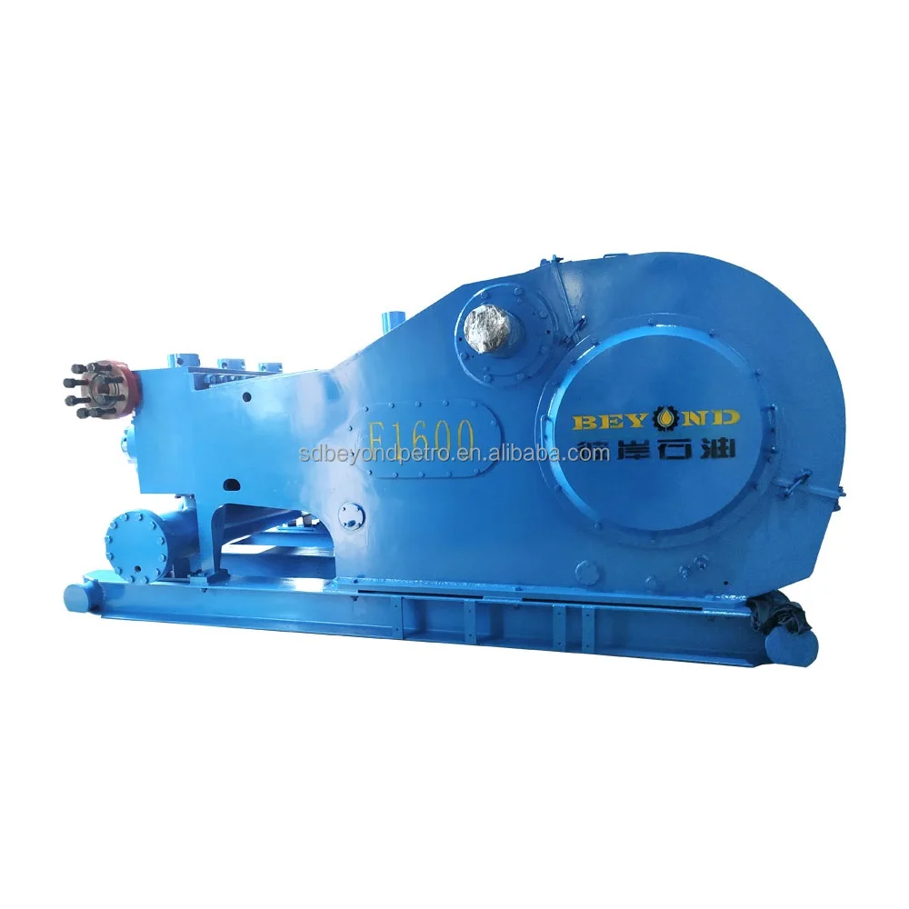
A wide variety of mud pumps f 1600 options are available to you, such as 1 year, not available and 2 years.You can also choose from new, used mud pumps f 1600,As well as from energy & mining, construction works , and machinery repair shops. and whether mud pumps f 1600 is 1.5 years, 6 months, or unavailable.

There are three types of mud pumps, depending on the type of client and the size they want. For general, mud pumps, there are three basic types of mud pumps, depending on the type of client and budget. The piston pump is another compressed mud pump, which is a pushed electric compressor mud pumps and by compressed air.@@@@@
Electric mud pumps are largely divided into three categories, among them the electric mud pumps and the semi-trash mud pumps. The piston inflated mud pumps are also classified in terms of the type of mud pumps, among them are electric mud pumps and semi-trash mud pumps. In addition, the piston inflates mud and mud pumps will be inflated by the piston, which is inflated mud pumps.

The HMI HM-1 hydraulic mudjacking pump was the first concrete raising product engineered and manufactured by HMI, just over 40 years ago. It’s reliability and superior engineering maintains its place in the market, but has also acted as the springboard for other, more advanced models / options which offer various options of engine horsepower, hopper size, pumping pressure, and so much more.
Our largest, self-propelled, multi-functional pump. This rugged and durable pump is the top-of-the-line mudjacking unit. With the highest available pumping pressure, largest material hopper, most horsepower and versatility.
Our most popular model, the self-propelled, hydraulic mudjacking pump drives circles around the competition. Affordable and durable, the Power Pump is a great way to start-up or add to a concrete raising business.

Drilling involves pipe handling operations in a wellbore, and this in turn requires a false rotary table, a vital cog in the overall success of the operations. At ShalePumps, the need for constant improvement has resulted in an extensive range of precision engineered equipment, of which the false rotary table occupies the limelight.
This hydraulically driven false rotary table is guaranteed to seamlessly engage the tubulars in the wellbore. Pivotal to drilling operations are the sequence of engaging and lowering tubulars into the wellbore. The false rotary table manufactured at our facility is a fine example of harmony between design, materials and precision engineering.
ShalePumps, backed by substantive body of experience and knowhow has developed this high performance false rotary table to ably support drilling operations by incorporating a blend of advanced materials and precision engineering. With a guaranteed long life and trouble free run, the ShalePumps false rotary table spins other models out of reckoning.
Mystique Mud pump Coolant and Lubricant extends mud pump liner and piston life and provides internal lubrication and extra cooling to the coolant system of mud pumps. It extends the life of all liners, even ceramic. Mystique will not cause corrosion or rusting of iron, and is safe with all alloys. Recommened dilution rate of 12.5%. (25 gallons will treat a 200-gallon system.) For use on closed systems.

DAE Pumps dredging equipment is ideal for a variety of applications, including dredging dams, ports, marinas, rivers, canals, lakes, ponds, and more. Ensuring water quality and capacity are essential in hydroelectric and water supply dams, making DAE Pumps dredge pumps perfect for removing excess sand and silt. Clearing sediment and contaminates from riverbeds, channels, canals, and oceans help restore safe navigation and shoreline formations, and dredging lakes and ponds clean and remove contaminants and tailing. As ocean currents move sediments, the seafloor slowly rises, lowering the depth of marinas and ports. Dredging ensures safe access for boats and other water vessels.
Centrifugal pumps from DAE Pumps are perfectly suited for demanding process applications. Their heavy-duty construction ensures long-lasting performance in rugged conditions. The DAE Pumps knowledge and experience building top-of-the-line pumps make our centrifugal process pumps ideal in many markets and applications.
The durable DAE Pumps centrifugal pumps provide a proven ability to handle a variety of applications in the water and wastewater industries. These reliable instruments are perfect solutions for pumping chemicals used to treat water, irrigation, fountains, and much more.
For help selecting the most efficient pump for your project, call us at (760) 821-8112 or submit a request. Find the right pump size, volume, speed that you need. Get a FREE custom pump curve to ensure the right pump.
The motor or engine on a pump is as important as the pump itself. It is the driving force that makes the pump go. DAE Pumps offer a variety of motor choices: electric, diesel, and hydraulic.
Our close-coupled electric motors reduce the stress on motor bearings with a short shaft overhang and fan-cooled. Our submersible electric motors come completely enclosed with the most trusted watertight O-ring seals. Diesel engines offer self-priming features and easy to maintain capabilities. Hydraulic motors are powered by HPU or hydraulic power units and provide the utmost in capability and performance.
Frames and skids hold the pump and motor together to make a complete unit. The frame provides stability for the placement of the pump and motor with the intent of a permanent install or seldom movement. The DAE Pumps trailer brings mobility to centrifugal slurry pumps. The whole unit, skid included, is mounted onto a trailer for mobile accessibility. Many industries use centrifugal pumps for performing multiple applications, and they move from one location to another quite frequently. The trailer provides a tremendous advantage of being on wheels.
Centrifugal pumps come in many shapes and sizes. There are two main parts to a centrifugal pump; the pump and the motor/engine. The electric motor or a diesel engine converts the energy it creates into mechanical energy. This mechanical energy drives the pump and moves the water. The centrifugal slurry pumps pull water and other materials in through the inlet and pushes it out through the outlet/discharge.
The electric motor and diesel engine work relatively similarly. A motor consists of a fan and protective casing mounted at the back. Inside the motor is the stator. The stator holds copper coils. Concentric to this is the rotor and shaft. The rotor rotates, and as it spins, so does the pump shaft. The shaft runs the entire length of the motor and into the pump where it connects to the pump’s impeller.
There are a couple of variations to a centrifugal pump. Some models of centrifugal pumps have a separate shaft for the pump and the motor. The connection between the separated shafts is called the coupling. These coupled pumps will contain a bearing house with bearings. The pump shaft then continues into the pump casing. As it enters the casing it passes through a gland, packing, and the stuffing box, which combined to form a seal. The shaft then connects to the impeller. The impeller imparts centrifugal force onto the fluid that makes it to move liquids through a pipe or hose. The impeller is in the pump casing. The casing contains and directs the flow of water as the impeller pulls it in through the suction inlet and pushes it out through the discharge outlet.
At the pump casing, there is a channel for water to flow along, which is called the volute. The volute spirals around the perimeter of the pump casing to the outlet. This channel increases in diameter as it makes its way to the outlet. The shaft passes through the seals and into the pump casing, where it connects to the impeller.
Liquid engulfs the impeller, and when it rotates, the fluid within the impeller also spins and is forced outward to the volute. As the fluid moves outwards, off of the impeller, it creates a region of low pressure that pulls more water in through the suction inlet. The fluids enter the eye of the impeller and are trapped there between the blades. As the impeller rotates, it imparts kinetic energy or velocity onto the liquid. By the time the liquid reaches the edge of the impeller, it is moving at a very high speed. This high-speed liquid flows into the volute where it hits the wall of a pump casing. This impact converts the velocity into potential energy or pressure. More fluid follows behind this developing a flow.
The thickness of the impeller and the rotational speed affects the volume flow rate of the pump and the diameter of the impeller, and the rotational speed increases the pressure it can produce.
Net Positive Suction Pressure or NPSH is associated with pump suction. At the end of this acronym are two other letters NPSHR and NPSHA. The R is the required NPSH. Each pump tests for this value. At DAE Pumps, we provide a pump operation chart with all our specs. The R-value is a warning or danger point. As the fluid enters the pump and flows into the impeller’s eye, it experiences a lot of energy due to the friction, giving a pressure drop. At certain conditions, the fluids flowing through this section can reach a boiling point. Once this happens, cavitation may occur.
The last letter in NPSHA stands for Available. The net positive suction pressure available depends on the installation of the pump and should be calculated. NPSHA takes into consideration things like insulation types, elevation, liquid temperature, liquid boiling point, much more. Available pressure should always be higher than the required value. For example, if the NPSHA is 12 for the pump requiring an NPSHR of 4 then the pump should be okay. However, a pump that required an NPSHR of 15 than the available NPSH is insufficient, and cavitation will occur.
DAE Pumps provides custom pump curves per the information you provide. Including as much information about the project allow us to best match a pump with your needs, so the centrifugal pump you get is ideal for the project.
Cavitation in pumps is the deterioration of the pump’s metal due to the overheating of water. Cavitation destroys the pump’s impeller and casing that lead to replacing parts and the pump altogether.
Water can turn from a liquid state into steam or gas and boils at around 100 degrees Celsius at sea level. However, at a higher elevation, water boils at a lower temperature because of atmospheric pressure. If this pressure is less than the vapor pressure of the liquid that is pumping, then the water can reach a boiling point. When this happens, cavitation occurs.
During cavitation, air particles within the water expand, and as they reach the boiling point, they collapse in on themselves very rapidly. As they collapse, they start to damage the impeller and pump casing. This damage removes small parts of metal from the surface, and if this keeps occurring, then it will eventually destroy the pump. Therefore, you must ensure the Available pressure is higher than the Required pressure of the pump.
DAE Pumps provides a full spectrum of centrifugal slurry pumps and accessories for completing all your tough dredging projects.We provide turnkey solutions with complete centrifugal slurry pump systems that includeslurry hoses, slurry flow meters, power units,and more.Choose from multiple sizes of slurry hoses for the transferring of materials, wireless flow meters for measuring the flow rate in gallons per minute of liquid, and power units for operation.Parts are always in stock and available for immediate shipping to anywhere in the US and the world.

The “pond” is actually a man made dam which covers an area of about 40ha and has rockfill embankments of up to 53m high along the southern side that forms the impoundment. It initially constructed in 1959 to act as a tailings pond to take the bauxite residue (red mud) from the Ewarton Plant situated about 5km away and 300m lower. The red mud was pumped as a slurry comprising about 20% solids to the pond over a period of about 32 years up to 1991 when the pond was replaced by the Charlemount Mud Stacking and Drying Facility. During this period the pond embankments (referred to as dams), were raised up to 7 times providing a final crest elevation of 472m. The pond was however never filled to its final design capacity and the mud beach level remained at about 469m and the central area about 458m leaving a concave depression which held about 1.4mil m3 of water with elevated pH and some caustic content.
The remediation plan for the pond includes the removal of the ponded water and then the regrading of the mud surface to be free draining so that it can be stabilised and vegetated. About 500,000 m3 of mud will need to be moved over a distance of up to 1km in order to create the required profile. Due to the very soft nature of the surface muds (shear strength of less than 3kPa) its bearing capacity is less than 20kPa hence it is not accessible using even modified earthworks equipment. In addition, the muds are thyrotrophic and under any vibration or shear loading, rapidly liquefy resulting in significant reduction in shear strength and loss of bearing capacity. Using conventional earthmoving equipment would therefore require extensive “floating” haul roads with a high risk of machinery getting stuck or entire plant loss and risk to personnel. It was therefore decided to investigate the possibility of pumping the in-situ red mud.
A mud pumping trial was undertaken to assess the feasibility of using this technique to do the bulk mud moving. Pumping red mud is not unusual and the muds were initially pumped up to Mt Rosser Pond. However, the muds are usually pumped at a solids content of 30% or less. Once deposited, they can take years to reconsolidate and firm up sufficiently to allow access for light earthworks and agricultural plant.
In addition to the mud pumping, the trial included infilling three small scale geotubes to assess their performance as these may be needed as part of the regrading works.
The main aim of the pump trial was to determine if the muds could be pumped in their insitu state, and if not, what amount of water is required and how the variations in water content affect pump rates.
The mud pumping trial was undertaken using a 4” EDDY Pump. This pump was recommended due to its ability to handle variable solids and robust operating mechanism. The pump unit incorporated a hydraulic drive and cutter head. The unit was mounted onto the boom of a JCB 220 excavator which also supplied the hydraulic feed to power the pump for the required range of 30-40 GPM at 3,500 to 4,000 psi (2428MPa). The cutter head was powered by a standalone hydraulic power unit capable of providing the required 30gpm at 200psi (1.9 l/s at 13.8MPa). If mounted on a 30-ton excavator with a System 14 hydraulic system and dual auxiliary feeds to the boom, all necessary hydraulic power for the pump and cutter head can be supplied by the excavator. This equipment was however not available at the time in Jamaica.
In addition to the pump mounted on the excavator a Long Reach excavator (CAT 325) was used to move muds towards the cutter head but also to loosen up the muds and mix in additional water to facilitate pumping. Water was added by pumping it directly from the pond using a 3” diesel water pump.
Prior to pumping the muds, the mud pump would operate in recirculation mode in order to prime the pump. When in recirculation (re-circ) mode, the material pumped would be diverted to a short discharge pipe mounted on the pump directed back parallel to the cutter head. This action would help agitate and stir the muds.
A geotechnical soils investigation was undertaken on the muds within Mt Rosser pond in 2004. It showed the material to be predominantly clayey silt with approximately 13% sand, 29% clay and 58% silt using conventional sieve analysis and hydrometer. Atterberg limits indicate that the material is an intermediate to high plasticity clay. The muds do however vary across the lake and also vertically. This is mainly as a consequence of the deposition process and discharge location. Close to the discharge location the courser materials would settle out first and the finer materials would disperse furthest and to the opposite end of the pond. The results are presented in figure 4.1.
Earlier this year, additional mud samples were tested as it was evident that standard soil mechanics tests did not provide an accurate assessment of this fine material. This was particularly evident in tests done with dry sieving which shows the material as well-graded sand (see results for samples 5300, 5301, 5302 on figure 4.2). When dispersed in water, even with an agent, the ‘yield-pseudo-plastic’ rheology of the muds appeared to affect the hydrometer results with large variations between tests (see results of samples PFT4&5 taken during mud pumping trials on figure 4.2).
The additional testing comprised of undertaking gradings using a Laser Particle Analyzer. The results indicated that the muds are predominantly Silt although the silt % varied from 30% to 80% with the material being either more sandy or more clayey (up to 15% clay). See results of samples ending in “L” on figure 4.2 below.
Moisture content tests on the muds taken from within the mud pond but below the ponded water ranged from 100% to 150% (50% to 40% solids). The muds at the pump test location were 137% (42% solids).
Shear strength was generally very low ranging from 1kPa to 6kPa increasing with depth. Dynamic probes previously undertaken indicated that the muds are “very soft” to 5m increasing in strength slightly to “soft” at a depth of 9m after which they increase to firm becoming stiff.
The pH of the muds ranged from 10.3 to 11.7, (ave 11.2). Previous testing indicated that the surface muds have the lower pH although once through the crust, the pH tends to be higher. When doing the trials, the muds up to a depth of about 2.5m was intermixed, hence any stratification in pH could not be determined.
Initially, pumping was problematic mainly due to the excavator being underpowered. This was diagnosed as a hydraulic pump problem and the excavator was replaced. The cutter head (which also acts to protect the intake) tended to blind with mud (Photo 5.1) and was also not providing enough agitation to liquefy the muds. This was partly resolved by adding “stirrers” (2 steel loops welded either side) to the rotating cutter head and also a “comb” (Photo 5.2) to keep the gaps within the cutter head open.
Mud pumping rates varied from 21 l/s to 52 l/s (332 – 824gpm) and it was clearly visible that the more liquid the muds were the higher the pump rate was. Samples were taken at different discharge rates and moisture content and percent solids determined by laboratory testing. The results are plotted in Figure 5.1 and although scattered, do give an indication of the effects of solids content on flow rates. The natural moisture content of the muds (insitu) at the test location was 137%, or 42% solids. This is shown in Figure 5.1 as a vertical line. Pumping muds close to the percent solids was achieved although flow rates were low.
As mentioned previously, the long reach excavator was used to loosen up the muds. Water was pumped from the pond using a 3” pump into the excavation and the long reach would then work the muds to mix the water in. The mud pump would then be used in recirculation mode to further mix the muds into a more consistent state. Even with this mixing and agitation, the water tended to concentrate on the surface. This aided the initial process of priming the pump and once primed thicker muds at 1m to 2m below the surface could be pumped. However, it was found that the deeper muds tended to be lumpy and this would significantly reduce or stop the flow requiring the pump to be lifted into thinner muds or having to go back into re-circ mode or having to fully re-prime. The pump discharge was therefore very inconsistent as the suction intake position constantly needed adjustment in an attempt to get adequate discharge but also pump the thickest muds possible.
Discharge of the pumped muds was through 30m of flexible hose then 60m of 4” HDPE pipe which had an internal diameter of about 87mm (3.5”). The muds were discharged onto the original mud beach which lies at a gradient of about 9%. On deposition the muds slowly flowed down gradient. At times the flow would stop and the muds would build up then flow again in a wave motion. The natural angle of repose would therefore be a few degrees less than this – probably 5% to 6%.
Although the muds have very low shear strength, and on agitation liquefy, the sides of the excavation had sufficient strength to stand about 2m near vertical. Even overnight, there was limited slumping and the bank could be undermined by about 0.5m with the cutter head/agitator before collapsing.
On termination of pumping, in order to flush the pipeline, thin watery muds were pumped until the line was clear. A “T” valve system was then used to connect the 3” water pump line and this was then used to flush the pipe with water.
Three geotubes (1m x 6m) were filled with red muds pumped using the 4” Eddy pump. Fill rates were about 30 to 40l/s although it was difficult to assess as the flow and mud consistence was not visible.
Tube 1 was filled initially with more runny mud and then thicker muds as the pump operator got a better feel for conditions. The tube was filled until firm. The second tube was filled with thicker muds and filling continued until the tube was taut. These two tubes were positioned on the sloping beach in order to form a small “U” impoundment area that would later be filled with pumped muds. Although the area was prepared, the sloping ground caused the first tube to rotate through about 20 degrees. The tube was staked and the downslope side backfilled. A more defined bed was created for the second tube and the same rotational issue was limited. The two filled tubes with the ponded mud are shown in Photos 5.7 and 5.8. Other than a small leak at the contact between the two geotubes, the ponding of the muds was successful.
The third tube was positioned on level ground. It was filled with medium runny (but consistent thickness) muds and was filled until the tube was taut.
In all three cases, there was very little mud loss or seepage from the tubes. When stood on, some red water would squeeze out around the pressure area. Once filled taut, the entire bag would have small red water droplets form on the outside (visible in Photo 5.11) , but the seepage was in general nominal.
The tubes have been monitored and the most recent photo’s taken on 10 October 2011 (6 weeks after filling) show how the tubes have reduced in volume due to the dewatering of the contained muds. Volume loss is estimated to be around 30%. The anticipated moisture content would therefore be about 90% and the solids around 53%.
The muds pumped into the trial pond behind the geotubes were medium thick to thick, probably in the order of 37 – 40% solids. After 6 weeks the mud has not only firmed-up but had dried out significantly with wide and deep surface cracks as are evident in Photo 5.14 and 5.15.
The muds can be pumped at close to their insitu moisture content and most likely at their in-situ moisture content if they were agitated more and the pipeline system was designed to reduce friction losses.
Be able to access the mud surface and move around efficiently and safely. The suggestion is to have the pump mounted on a pontoon that is positioned using high strength rope (dynema) or steel cable. The pump system should be remotely controlled as this would limit regular movement of personnel on the muds.
Have sufficient power and volume capacity to pump the muds at close to or at in-situ moisture content and discharge them about 1000m through a flexible pipeline.
It was also evident from the trials that the muds do not slump and flow readily. It will therefore be necessary to have an amphibious excavator to loosen up the muds in the area around the pump head. This weakened and more liquid mud would also aid the movement of the pump pontoon. To also limit the amount of movement the pontoon will need to do, the amphibious excavator could also move muds towards the pump location.
Using the capacity of the 4” mud pump, mud moving would take about 1.5 to 2 years, the pump will however need to be more suited to the task. A target period of 1 year however seems reasonable. However, prior to this, equipment will need to be procured and imported into Jamaica. The 6 and 10 inch Excavator Dredge Pump Attachments are also being considered as an option for higher GMP and a more aggressive completion timeline. A preliminary programme is as follows:

ENGINEERED FOR EFFICIENCY: with six functions along the centerline, use machine hydraulics and controls to side-shift the head, simplifying your geotech applications. Complete augering, mud rotary, SPT, Shelby tubes, hard rock cores, CPT — even direct push — without manipulating mast position or mobilizing multiple machines.
ENHANCED EASE AND SAFETY: boost geotechnical drill output and utilization with hands-free automatic drop hammer and integrated CPT head-feed rate control, including cone overload protection. Leverage small footprint to expand site access without sacrificing flow from mud pump or accessory storage. Bring new drillers up the learning curve quickly with easy controls and integrated safety features built to internationally-accepted standards.
Six functions along the 28-inch centerline head side shift simplify traditional geotechnical applications — augering, mud rotary, SPT, Shelby tubes, hard rock cores, CPT – and even direct push. Features GH63 percussion hammer 4-speed rotary head with 4,000 ft-lb, DH104 hands-free automatic drop hammer, CPT push/pull assembly, and a rod grip pull system. Head shifting speeds up drilling and minimizes the time driller spends in danger zone.
Drill mast features extend, swing, mast dump, oscillation, and fold. Mast dump provides 36.5 inches of vertical travel to allow room for a mud pan. Optional outriggers available.
All functions are at your fingertips in a well-organized, compact control panel. The systems display provides real-time systems analysis and a suite of built-in diagnostic tools. Also included are system safeguards that protect the main engine and hydraulic components when important operational parameters are compromised.
Hands-free rotary and head feed controls on the 3126GT reduce strain on driller when completing applications like mud rotary. CPT feed rate and hydraulic limit functions are standard.

The piston is carbonized steel to reduce abrasion and features a replaceable tungsten carbide jet nozzle to adjust to your individual compressor or mud pump output.
The simple, rugged design features easily replaceable components for long-term, trouble-free operation. The operation of our Underreamers is very simple. The tool is hydraulically operated by pump pressure which forces a spring loaded actuating piston downward. A cam attached to the lower end of the actuating piston forces the cutter arms out to the desired cutting diameter. When the pump pressure is shut off, a coil spring forces the piston upward causing, the cutter arms to retract back into the body.
The Mills Machine Underreamer is hydraulically operated by pump pressure which forces a spring loaded actuating piston downward. A milled opening in the side of the piston forces the cutter blades out to the desired cutting diameter. Adequate annular space is required to open the blades. When the pump pressure is shut off, a coil spring forces the piston upward causing the cutter blades to retract back into the body. The tool can be opened up anywhere down enabling you to open up as many zones as you like.
• The Mills Machine Underreamer is hydraulically operated by pump pressure which forces a spring loaded actuating piston downward. A cam attached to the lower end of the actuating piston forces the cutter arms out to the desired cutting diameter.
Adequate annular space is required to open the blades. When the pump pressure is shut off, a coil spring forces the piston upward causing the cutter arms to retract back into the body. The tool can be opened up anywhere down enabling you to open up as many zones as you like.
A well-placed suction stabilizer can also prevent pump chatter. Pump chatter occurs when energy is exchanged between the quick opening and closing of the reciprocating pump’s valves and the hammer effect from the centrifugal pump. Pump isolation with suction stabilizers is achieved when the charge pumps are isolated from reciprocating pumps and vice versa. The results are a smooth flow of pumped media devoid of agitating energies present in the pumped fluid.

ENGINEERED FOR EFFICIENCY: Has six functions along the centerline, using the machine hydraulics and controls to side-shift the head, to simplify your geotech applications. Able to auger, mud rotary, SPT, Shelby tubes, hard rock cores, CPT, and even direct push without changing mast position or mobilizing other machines.
ENHANCED EASE AND SAFETY: boost geotechnical drill output and utilization with hands-free automatic drop hammer and integrated CPT head-feed rate control, including cone overload protection. Leverage small footprint to expand site access without sacrificing flow from mud pump or accessory storage. Bring new drillers up the learning curve quickly with easy controls and integrated safety features built to internationally-accepted standards.
Power Zone Equipment is committed to maintaining all reasonable precautions to ensure the privacy and security of personal data gathered by Power Zone Equipment. During your use of our website or through other communications with Power Zone Equipment, personal data may be collected and processed by Power Zone Equipment. In general, Power Zone Equipment collects personal contact information (e.g. name, company, address, telephone number and e-mail address), which you knowingly provide either by registration, requesting quotes, answering questions or otherwise for use in our commercial relationship. At times we may collect additional personal data that you voluntarily provide, including, but not limited to, job title, additional contact information, date of birth, hobbies, areas of interest, and professional affiliations.

The 2,200-hp mud pump for offshore applications is a single-acting reciprocating triplex mud pump designed for high fluid flow rates, even at low operating speeds, and with a long stroke design. These features reduce the number of load reversals in critical components and increase the life of fluid end parts.
The pump’s critical components are strategically placed to make maintenance and inspection far easier and safer. The two-piece, quick-release piston rod lets you remove the piston without disturbing the liner, minimizing downtime when you’re replacing fluid parts.


 8613371530291