
mud pump assembled piston free sample
A wide variety of mud pump rubber piston assembly options are available to you, such as 1 year, not available.You can also choose from new, mud pump rubber piston assembly,As well as from energy & mining, construction works , and machinery repair shops. and whether mud pump rubber piston assembly is 1.5 years, 6 months, or unavailable.

The 2,200-hp mud pump for offshore applications is a single-acting reciprocating triplex mud pump designed for high fluid flow rates, even at low operating speeds, and with a long stroke design. These features reduce the number of load reversals in critical components and increase the life of fluid end parts.
The pump’s critical components are strategically placed to make maintenance and inspection far easier and safer. The two-piece, quick-release piston rod lets you remove the piston without disturbing the liner, minimizing downtime when you’re replacing fluid parts.

For drilling companies with the need to pump slurries with bentonite, concrete, and other thick mud, Elepump triplex, high pressure piston mud pumps are the ideal choice for long life and minimal maintenance.
Featuring superior construction and high quality materials, Elepump mud pumps are built to last. They require minimal maintenance, so your costs stay low so and your drilling operations stay profitable.
The KT-45 mud pump is the most compact of the whole range of Elepump pressure pumps. This small capacity pump is still mighty enough to pack a big punch, with enough flow for drilling up to HQ sizes. It is very light and very maneuverable, making it a great choice for geotechnical drilling, fly jobs or heliportable jobs. Elepump mud pumps can be configured for diesel, gas, electric and air power.
The KF-50M is the pump to choose if you want a pump you can count on to keep pumping without missing a beat. This powerful pump is a standard size and can handle all slurries including bentonite, concrete and more. With its stainless steel ball and seat style valves, it is the ideal choice for pumping grit, cement, chunks of rock and other hard material, without the worry of damage to fragile parts. Elepump mud pumps can be configured for diesel, gas, electric and air power.
TECHNICAL FIELD OF THE INVENTION The present invention relates generally to piston seals for mud pumps and more particularly to a replaceable piston seal. Still more particularly, the present invention relates to a durable polymeric piston seal constructed with very small tolerances so as to provide a precise interference fit with the corresponding liner.
Slush or mud pumps are commonly used for pumping drilling mud in connection with oil well drilling operations. Because of the need to pump the drilling mud through several thousand feet of drill pipe, such pumps typically operate at high pressures. Moreover, it is necessary for the mud to emerge from the drill bit downhole at a relatively high velocity in order to provide lubrication and cooling to the bit and to provide a vehicle for the removal of drill cuttings from the earth formation being drilled. Lastly, the pressure generated by the mud pump contributes to the total downhole pressure, which is used to prevent well blowouts.
The pistons and cylinders used for such mud pumps are susceptible to a high degree of wear during use because the drilling mud is relatively dense and has a high proportion of suspended abrasive solids. As the pump cylinder becomes worn, the small annular space between the piston and the cylinder wall increases substantially and sometimes irregularly. For these reasons, the seal design for such pumps is critical.
The high pressure abrasive environment in which the pumps must operate is especially deleterious to the seals since considerable friction forces are generated, and since the hydraulic pressures encountered during operation force the seal into the annular space between the cylinder wall and the piston. In some instances, the frictional forces may even detach the seal from the piston. In these instances, the edges of the seal can become damaged very quickly by the cutting or tearing action that occurs as a result of piston movement. Another problem with conventional mud pump seals is that they do not adequately "wipe" the
Attempts have been made to retain the seal in the piston so as to resist this frictional force. One conventional solution to this problem has been use of a metallic seal retainer which is disposed over the seal body and retained in place by snap rings. One disadvantage of this solution, however, is that the additional seal retaining element and its snap rings render the overall piston construction more expensive. A further disadvantage is that the seal is made somewhat less flexible and resilient than it would otherwise be, thus decreasing its ability to wipe the cylinder wall effectively. Another conventional solution to the sealing problem comprises including a seal retaining ring or reinforcement in the seal itself. In this case, the retaining ring or reinforcement is molded into the seal material. As with the external retaining ring, this solution decreases the flexibility of the seal and increases its cost of manufacture.
It is common to incorporate the foregoing seals into piston heads wherein the seal is permanently affixed to the piston head. This is disadvantageous because the seal tends to wear much faster than the piston head, resulting in waste and unnecessary expense when the whole piston head has to be replaced because of wear to the seal member. It is therefore desirable to provide a piston seal that is removable from the piston head and thus can be replaced without requiring replacement of the whole piston head. The nature of the mud pump operating environment makes it difficult to effectively address these issues. It is, therefore, desired to develop a new and improved replaceable seal for a reciprocating mud pump piston that overcomes the foregoing difficulties while providing better wear properties and more advantageous overall results.
BRIEF SUMMARY OF THE INVENTION The present invention comprises a new and improved replaceable seal for a reciprocating mud pump piston. The present seal does not require any external seal retaining means and is free from any incorporated seal retainer or reinforcement. The present seal is manufactured to precise specifications that minimize play between the seal, piston head and cylinder and also compensate for the slight deformation of the seal member that occurs when the seal member is demolded and cured.
Figure 3 is a cross sectional view of the sealing member of Figure 2 mounted on a piston head in a cylinder. DETAILED DESCRIPTION OF THE PREFERRED EMBODIMENTS
Referring initially to Figure 1, a typical prior-art mud pump piston assembly comprises a piston head 10 and a sealing device or seal 15 therefor slidably received in a piston cylinder 12. Piston head 10 comprises a generally cylindrical body having a flange 11 extending therefrom. Piston head 10 is typically made of steel, such as AISI 4140. Seal 15 is friction fit on piston head 10 and abuts flange 11. Seal 15 comprises an elastomeric sealing section 14 and a heel section 13. These sections are either integrally formed or bonded together. Heel section 13 is typically made from a stack of several layers of rubber- impregnated fabric, which give it a higher modulus of elasticity than the elastomeric sealing section 14. In prior art mud pumps, the heel section 13, which is stiffer than the elastomeric sealing section, resists extrusion into the gap between the cylinder and piston flange to some extent. However, heel section 13 is still forced into the gap under the influence of the hydrostatic pressure in locations where wear occurs. Reference numeral 18 designates a portion of heel section 14 that has been extruded into the gap 20 between the flange 11 and the cylinder 12. Both elastomeric sealing section 14 and heel section 13 make intimate contact with the cylinder 12. Seal 15 is held in place by a retaining ring 16 and a snap ring 17, which hold seal 15 in place and permit replacement thereof. Easy replacement of seals is a desirable feature for a mud pump, since seals typically wear out long before the other mud pump components and must be replaced in order to continue pumping operations. The direction of travel of piston 10 is shown by arrow 19. The direction of the hydrostatic pressure force exerted by the working fluid of the pump is shown by arrows 21. This force axially compresses elastomeric sealing section 14 and heel section 13 and radially expands these sections against the cylinder wall.
Referring now to Figure 3, the seal 22 of Figure 2 is shown mounted on a piston head in a cylinder. It can be seen that sealing lip 24 is compressed radially and conforms to the inside of 12. In addition, in order to enable seal 22 to be used without a reinforced heel section, piston head 10 is manufactured to extremely tight tolerances. In particular, it has been discovered that the life of seal 22 can be greatly prolonged by ensuring that play between flange 11 and cylinder 12 is minimized at the outset. Thus, the average width of the annular gap 25 between flange 11 and cylinder 12 is much smaller than in previously known devices. In this regard, it is preferred that the difference between the outside diameter of flange 11 as manufactured and the inside diameter of cylinder 12 as manufactured be less than 0.010 inches, and more preferably less than 0.008 inches. By way of example, flange 11 of a 6 inch piston is preferably about 0.002 to 0.010 inch smaller than the associated bore.
As can be seen in the Figures, the sealing lip 24 of seal 22 is preferably somewhat larger than the nominal inside diameter of the cylinder 12. Again by way of example, for a piston having a nominal diameter of six inches, sealing lip 24 preferably has a diameter of about 6.25 inches. Thus, in one preferred embodiment, diameters are as follows: for metal flange 11, df = 5.990; for cylinder 12, inside diameter idi = 6.000; for seal lip 23, ds = 6.250; and for heel 24, dh = 5.990.
Although the invention is described with particular reference to a pump piston used with slush or mud pumps, it will be recognized that certain features thereof may be used or adopted to use in other types of reciprocating pumps. Likewise it will be understood that various modification can be made to the present seal without departing from the scope of the invention. For example, the relative dimensions of various parts, the materials from which the seal is made, and other parameters can be varied, so long as the seal retains the advantages discussed herein.

Cavitation is an undesirable condition that reduces pump efficiency and leads to excessive wear and damage to pump components. Factors that can contribute to cavitation, such as fluid velocity and pressure, can sometimes be attributed to an inadequate mud system design and/or the diminishing performance of the mud pump’s feed system.
When a mud pump has entered full cavitation, rig crews and field service technicians will see the equipment shaking and hear the pump “knocking,” which typically sounds like marbles and stones being thrown around inside the equipment. However, the process of cavitation starts long before audible signs reveal themselves – hence the name “the silent killer.”
Mild cavitation begins to occur when the mud pump is starved for fluid. While the pump itself may not be making noise, damage is still being done to the internal components of the fluid end. In the early stages, cavitation can damage a pump’s module, piston and valve assembly.
The imperceptible but intense shock waves generated by cavitation travel directly from the fluid end to the pump’s power end, causing premature vibrational damage to the crosshead slides. The vibrations are then passed onto the shaft, bull gear and into the main bearings.
If not corrected, the vibrations caused by cavitation will work their way directly to critical power end components, which will result in the premature failure of the mud pump. A busted mud pump means expensive downtime and repair costs.
To stop cavitation before it starts, install and tune high-speed pressure sensors on the mud suction line set to sound an alarm if the pressure falls below 30 psi.
Although the pump may not be knocking loudly when cavitation first presents, regular inspections by a properly trained field technician may be able to detect moderate vibrations and slight knocking sounds.
Gardner Denver offers Pump University, a mobile classroom that travels to facilities and/or drilling rigs and trains rig crews on best practices for pumping equipment maintenance.
Severe cavitation will drastically decrease module life and will eventually lead to catastrophic pump failure. Along with downtime and repair costs, the failure of the drilling pump can also cause damage to the suction and discharge piping.
When a mud pump has entered full cavitation, rig crews and field service technicians will see the equipment shaking and hear the pump ‘knocking’… However, the process of cavitation starts long before audible signs reveal themselves – hence the name ‘the silent killer.’In 2017, a leading North American drilling contractor was encountering chronic mud system issues on multiple rigs. The contractor engaged in more than 25 premature module washes in one year and suffered a major power-end failure.
Gardner Denver’s engineering team spent time on the contractor’s rigs, observing the pumps during operation and surveying the mud system’s design and configuration.
The engineering team discovered that the suction systems were undersized, feed lines were too small and there was no dampening on the suction side of the pump.
Following the implementation of these recommendations, the contractor saw significant performance improvements from the drilling pumps. Consumables life was extended significantly, and module washes were reduced by nearly 85%.
Although pump age does not affect its susceptibility to cavitation, the age of the rig can. An older rig’s mud systems may not be equipped for the way pumps are run today – at maximum horsepower.
As usual, winter — or the slow season — is the time most drillers take the time to maintain their equipment in order to get ready for the peak season. One of the main parts that usually needs attention is the mud pump. Sometimes, it is just a set of swabs to bring it up to snuff, but often, tearing it down and inspecting the parts may reveal that other things need attention. For instance, liners. I can usually run three sets of swabs before it is time to change the liner. New liners and swabs last a good long time. The second set of swabs lasts less, and by the time you put in your third set of swabs, it’s time to order new liners. Probably rods too. It’s not always necessary to change pistons when you change swabs. Sometimes just the rubber needs to be changed, saving money. How do you tell? There is a small groove around the outside of the piston. As it wears, the groove will disappear and it’s time for a new piston.
The wear groove on a piston can be a good indicator of the general health of your pump. If the wear is pretty even all around, chances are the pump is in pretty good shape. But if you see wear on one side only, that is a clue to dig deeper. Uneven wear is a sign that the rods are not stroking at the exact angle that they were designed to, which is parallel to the liner. So, it’s time to look at the gear end. Or as some folks call it, “the expensive end.”
The wear groove on a piston can be a good indicator of the general health of your pump. If the wear is pretty even all around, chances are the pump is in pretty good shape. But if you see wear on one side only, that is a clue to dig deeper.
After you get the cover off the gear end, the first thing to look at will be the oil. It needs to be fairly clean, with no drill mud in it. Also look for metal. Some brass is to be expected, but if you put a magnet in the oil and come back later and it has more than a little metal on it, it gets more serious. The brass in the big end of the connecting rod is a wearable part. It is made to be replaced at intervals — usually years. The most common source of metal is from the bull and pinion gears. They transmit the power to the mud. If you look at the pinion gear closely, you will find that it wears faster than the bull gear. This is for two reasons. First, it is at the top of the pump and may not receive adequate lubrication. The second reason is wear. All the teeth on both the bull and pinion gears receive the same amount of wear, but the bull gear has many more teeth to spread the wear. That is why, with a well maintained pump, the bull gear will outlast the pinion gear three, four or even five times. Pinion gears aren’t too expensive and are fairly easy to change.
This process is fairly straightforward machine work, but over the years, I have discovered a trick that will bring a rebuild up to “better than new.” When you tear a pump down, did you ever notice that there is about 1-inch of liner on each end that has no wear? This is because the swab never gets to it. If it has wear closer to one end than the other, your rods are out of adjustment. The trick is to offset grind the journals. I usually offset mine about ¼-inch. This gives me a ½-inch increase in the stroke without weakening the gear end. This turns a 5x6 pump into a 5½x6 pump. More fluid equals better holes. I adjust the rods to the right length to keep from running out the end of the liner, and enjoy the benefits.
Other than age, the problem I have seen with journal wear is improper lubrication. Smaller pumps rely on splash lubrication. This means that as the crank strokes, the rods pick up oil and it lubricates the crank journals. If your gear end is full of drill mud due to bad packing, it’s going to eat your pump. If the oil is clean, but still shows crank wear, you need to look at the oil you are using.
Oil that is too thick will not be very well picked up and won’t find its way into the oil holes in the brass to lubricate the journals. I’ve seen drillers that, when their pump starts knocking, they switch to a heavier weight oil. This actually makes the problem worse. In my experience, factory specified gear end oil is designed for warmer climates. As you move north, it needs to be lighter to do its job. Several drillers I know in the Northern Tier and Canada run 30 weight in their pumps. In Georgia, I run 40W90. Seems to work well.

An axial piston pump is a positive displacement pump that has a number of pistons in a circular array within a hydraulic motor or an automotive air conditioning compressor.
An axial piston pump has a number of pistons (usually an odd number) arranged in a circular array within a housing which is commonly referred to as a cylinder block, barrel. This cylinder block is driven to rotate about its axis of symmetry by an integral shaft that is, more or less, aligned with the pumping pistons (usually parallel but not necessarily).
Mating surfaces. One end of the cylinder block is convex and wears against a mating surface on a stationary valve plate. The inlet and outlet fluid of the pump pass through different parts of the sliding interface between the cylinder block and valve plate. The valve plate has two semi-circular ports that allow inlet of the operating fluid and exhaust of the outlet fluid respectively.
Protruding pistons. The pumping pistons protrude from the opposite end of the cylinder block. There are numerous configurations used for the exposed ends of the pistons but in all cases they bear against a cam. In variable displacement units, the cam is movable and commonly referred to as a yoke or hanger. For conceptual purposes, the cam can be represented by a plane, the orientation of which, in combination with shaft rotation, provides the cam action that leads to piston reciprocation and thus pumping. The angle between a vector normal to the cam plane and the cylinder block axis of rotation, called the cam angle, is one variable that determines the displacement of the pump or the amount of fluid pumped per shaft revolution. Variable displacement units have the ability to vary the cam angle during operation whereas fixed displacement units do not.
Reciprocating pistons. As the cylinder block rotates, the exposed ends of the pistons are constrained to follow the surface of the cam plane. Since the cam plane is at an angle to the axis of rotation, the pistons must reciprocate axially as they precess about the cylinder block axis. The axial motion of the pistons is sinusoidal. During the rising portion of the piston"s reciprocation cycle, the piston moves toward the valve plate. Also, during this time, the fluid trapped between the buried end of the piston and the valve plate is vented to the pump"s discharge port through one of the valve plate"s semi-circular ports - the discharge port. As the piston moves toward the valve plate, fluid is pushed or displaced through the discharge port of the valve plate.
Effect of precession. When the piston is at the top of the reciprocation cycle (commonly referred to as top-dead-center or just TDC), the connection between the trapped fluid chamber and the pump"s discharge port is closed. Shortly thereafter, that same chamber becomes open to the pump"s inlet port. As the piston continues to precess about the cylinder block axis, it moves away from the valve plate thereby increasing the volume of the trapped chamber. As this occurs, fluid enters the chamber from the pump"s inlet to fill the void. This process continues until the piston reaches the bottom of the reciprocation cylinder - commonly referred to as bottom-dead-center or BDC. At BDC, the connection between the pumping chamber and inlet port is closed. Shortly thereafter, the chamber becomes open to the discharge port again and the pumping cycle starts over.
Variable displacement. In a variable displacement pump, if the vector normal to the cam plane (swash plate) is set parallel to the axis of rotation, there is no movement of the pistons in their cylinders. Thus there is no output. Movement of the swash plate controls pump output from zero to maximum. There are two kinds of variable-displacement axial piston pumps:
direct displacement control pump, a kind of axial piston pump with a direct displacement control. A direct displacement control uses a mechanical lever attached to the swashplate of the axial piston pump. Higher system pressures require more force to move that lever, making direct displacement control only suitable for light or medium duty pumps. Heavy duty pumps require servo control.linkages and springs and in some cases magnets rather than a shaft to a motor located outside of the pump (thereby reducing the number of moving parts), keeping parts protected and lubricated and reducing the resistance against the flow of liquid.
Pressure. In a typical pressure-compensated pump, the swash plate angle is adjusted through the action of a valve which uses pressure feedback so that the instantaneous pump output flow is exactly enough to maintain a designated pressure. If the load flow increases, pressure will momentarily decrease but the pressure-compensation valve will sense the decrease and then increase the swash plate angle to increase pump output flow so that the desired pressure is restored. In reality most systems use pressure as a control for this type of pump. The operating pressure reaches, say, 200 bar (20 MPa or 2900 psi) and the swash plate is driven towards zero angle (piston stroke nearly zero) and with the inherent leaks in the system allows the pump to stabilise at the delivery volume that maintains the set pressure. As demand increases the swash plate is moved to a greater angle, piston stroke increases and the volume of fluid increases; if the demand slackens the pressure will rise, and the pumped volume diminishes as the pressure rises. At maximum system pressure the output is once again almost zero. If the fluid demand increases beyond the capacity of the pump to deliver, the system pressure will drop to near zero. The swash plate angle will remain at the maximum allowed, and the pistons will operate at full stroke. This continues until system flow-demand eases and the pump"s capacity is greater than demand. As the pressure rises the swash-plate angle modulates to try to not exceed the maximum pressure while meeting the flow demand.
Designers have a number of problems to overcome in designing axial piston pumps. One is managing to be able to manufacture a pump with the fine tolerances necessary for efficient operation. The mating faces between the rotary piston-cylinder assembly and the stationary pump body have to be almost a perfect seal while the rotary part turns at perhaps 3000 rpm. The pistons are usually less than half an inch (13 mm) in diameter with similar stroke lengths. Keeping the wall to piston seal tight means that very small clearances are involved and that materials have to be closely matched for similar coefficient of expansion.
The pistons have to be drawn outwards in their cylinder by some means. On small pumps this can be done by means of a spring inside the cylinder that forces the piston up the cylinder. Inlet fluid pressure can also be arranged so that the fluid pushes the pistons up the cylinder. Often a vane pump is located on the same drive shaft to provide this pressure and it also allows the pump assembly to draw fluid against some suction head from the reservoir, which is not an attribute of the unaided axial piston pump.
Another method of drawing pistons up the cylinder is to attach the cylinder heads to the surface of the swash plate. In that way the piston stroke is totally mechanical. However, the designer"s problem of lubricating the swash plate face (a sliding contact) is made even more difficult.
Internal lubrication of the pump is achieved by use of the operating fluid—normally called operating temperature, limited by the fluid, of about 120 °C (250 °F) so that using that fluid as a lubricant brings its own problems. In this type of pump the leakage from the face between the cylinder housing and the body block is used to cool and lubricate the exterior of the rotating parts. The leakage is then carried off to the reservoir or to the inlet side of the pump again. Hydraulic fluid that has been used is always cooled and passed through micrometre-sized filters before recirculating through the pump.
Despite the problems indicated above this type of pump can contain most of the necessary circuit controls integrally (the swash-plate angle control) to regulate flow and pressure, be very reliable and allow the rest of the hydraulic system to be very simple and inexpensive.
Axial piston pumps are used to power the hydraulic systems of jet aircraft, being gear-driven off of the turbine engine"s main shaft, The system used on the F-14 used a 9-piston pump that produced a standard system operating pressure of 3000 psi and a maximum flow of 84 gallons per minute.
Automotive air conditioning compressors for cabin cooling are nowadays mostly based around the axial piston pump design (others are based on the scroll compressor or rotary vane pump ones instead) in order to contain their weight and space requirement in the vehicle"s engine bay and reduce vibrations. They"re available in fixed displacement and dynamically adjusted variable displacement variants, and, depending upon the compressor"s design, the actual rotating swashplate either directly drives a set of pistons mated to its edges through a set of hemispherical metal shoes, or a nutating plate on which a set of pistons are mounted by means of rods.
Axial reciprocating motors are also used to power many machines. They operate on the same principle as described above, except that the circulating fluid is provided under considerable pressure and the piston housing is made to rotate and provide shaft power to another machine. A common use of an axial reciprocating motor is to power small earthmoving plant such as skid loader machines. Another use is to drive the screws of torpedoes.
AN OPERATIONAL SAFETY RELIEF VALVE MUST BE INSTALLED IN THE DISCHARGE LINE BETWEEN PUMP AND ANY OTHER PIPE FITTINGS. THIS RELIEF VALVE MUST BE SET AT THE RECOMMENDED RELIEF PRESSURE DESIGNATED ON THE PUMP APPLICATION TAG. CATASTROPHIC DESTRUCTION OF PUMP, PIPING, OR PERSONAL INJURY MAY RESULT IF DISCHARGE LINES ARE CLOSED WHEN THE PUMP IS STARTED, OR AFTER THE PUMP IS RUNNING.
Gears, connecting rod bearings and crossheads in all geared piston type pumps are lubricated by splash from lubricant in the crankcase. Crankshaft bearings and pinion shaft bearings in series 1800, 1500, 1600, 1700, 1900, and 2600 pumps are also lubricated from this same oil in the crankcase by splash. Shaft bearings in Series 1550-C, 1654-C, 2000 and 2200 pumps and in pumps with Serial Number 24523 and below are sealed off from the crankcase lubricant by oil seals and run in a separate bath of oil retained in the respective bearing housing.
WARNING -The crankcase is drained after testing pump at the factory. Remove crankcase cover or crosshead guide hand hole cover and fill with sufficient lubricant before starting the pump for the first time.
Quantity and type of lubricant required to fill crankcase to proper level is shown below. For chain and sprocket driven pumps use an SAE 30 high grade mineral oil in Crankcase.
For herringbone gear driven pumps operating in average climates, use SAE 90EP, AGMA 5EP, or AGMA 6EP gear lubricants. Be sure, however, to use an EP lubricant that will not have a corrosive action on Bronze and that it contains rust, oxidation and foam inhibitors. multi-purpose multi-viscosity gear lubricants are UNSATISFACTORY for use in GASO pumps.
For worm driven pumps, use an SAE 140 EP Gear Lubricant. Running temperature of crankcase oil should not exceed 180 degrees Fahrenheit. If higher temperatures occur and mechanical fits are found to be correct the use of a separate oil cooler is recommended. In addition, SAE EP 140 Gear Lubricant should be placed in separate bath bearings on pump where they are standard.
LUBRICATION OF SHAFT BEARINGS IN SERIES 1550-C, 16540C, 2000 and 2200 - (AND FOR PUMPS #24523 AND BELOW) These pumps are equipped with inner oil seals on pinion shaft and crankshaft, so they run in a separate bath of SAE EP 90 Gear Lubricant or SAE 50 high grade motor oil or mineral oil. The correct amount of oil is put into the bearing housings when pump is shipped from factory, but a check should be made to see that none has leaked out or been removed. Proper oil level is even with pipe plug in lower part of bearing housing flange or cover plate.
Pumps with herringbone gears #24523 and up do not have inner oil seals installed for the pinion and crankshaft bearings as standard equipment however, you pump may have these seals installed as special equipment. if your pump has inner oil seals installed, the amount of oil required for the crankcase is as follows:
To check for wear, place a wrench on the top connecting rod bolt and shake the rod parallel to the crankshaft. (The pressure must be relieved from the liquid end of the pump so that the pump"s mechanism is free to move.) If the rod bearing moves without resistance, the bearing may be too loose and need adjusting. If the bearing does need adjusting, remove shims until you cannot shake the rod, then add .005"" shims one at a time until there is a little side movement. Be sure to torque rod bolt nuts to proper value for each adjustment. (NOTE: If you are making this adjustment after having had the crossheads out, be sure that the oil holes in the rod are pointing up. The ""up"" side is indicated by matching numbers stamped on the cap and rod at the split between them. These numbers should be the same on each rod and should be on the top side of the crankshaft.) Turn the shaft by hand and if there is any hard drag or tight spots in the bearing, add another .005"" shim. After this bearing is properly adjusted, loosen bolts a few turns and repeat the above operation on the other bearings. After all bearings have been adjusted, torque all connecting rod bolt nuts back to proper amount. Again turn the pump by hand to check for excessive drag and tight spots. If none, the pump should then be ready for operation.
If the pump cannot be rotated by hand due to the drive being enclosed, the bearings may be completely adjusted by shaking the bearing on the shaft as stated above. Care must be taken not to over-tighten the bearings since they cannot be checked by rotating the pump by hand. When bearings are adjusted by this method, they must be watched carefully for overheating when the pump is put into operation.
Alternatively, plastic gauge strips, found in most parts stores may be used to adjust these bearings. It is usually better to have a bearing a little too loose than too tight. A slightly loose bearing will cause very little trouble because of the slow operating speeds of the pump, but a tight bearing will overheat and the babbitt may melt or pull. with experience, an operator can tell by feel when the bearings are properly adjusted. Normal precautions must be taken to insure cleanliness of parts upon their assembly. All wrenches used in adjusting these bearings are standard wrenches.
Bearings in the crosshead end are bronze bushings. To replace these bushings, remove connecting rod and crosshead assembly from pump. Press out the crosshead pin, and then remove and replace bushing. After the new bushing has been pressed into the connecting rod, it should be reamed for a loose fit on the crosshead pin as follows: .002"" for pumps Series 1500, 1800, and 1700, .0025"" for pumps Series 1600, and .004"" for pumps Series 2600.
Crankcase bearings for Series 1800, 1500, 1600, and 1700 pumps should have an end play in the crankshaft of: .001"" to .003"" for 1800 pumps .002"" to .004"" for 1500 pumps & 1600 pumps .003"" to .005"" for 1700 pumps
This end play is measured when pump is cold to allow for expansion due to heat under operating conditions. Bearings may be adjusted from one side only. To adjust bearings for end play, disconnect connecting rods, remove several shims (more than necessary) from under the bearing housing, tighten up on crankshaft bearing housings until bearings bind slightly when shaft is rotated by hand. Then measure the shim gap with a feeler gauge and add its equivalent plus from .001"" to .003"" of shim (for normal clearance) and tighten up on crankshaft bearing housing cap screws.
Crankshaft bearings for series 2600 Pumps have a .012"" to .013"" pre-load. To get this pre-load, try different thicknesses of shims until a slight drag is felt while rolling the shaft and then remove .012"" to .013"" of shims. When necessary to install new bearing cones on crankshaft, heat them in oil at 280 degrees Fahrenheit for easy installation. Be sure they are firmly against the shoulder on the crankshaft.
Please note: Improper application of heat to these bearings during their installation in GASO pumps will automatically revoke the warranty on the bearings. It is suggested that the procedures outlines above be closely followed when changing bearings. PINION SHAFT BEARINGS - The pinion shaft bearings are self-contained ball or roller bearings and have no adjustment for wear. Their load ratings are far above the load applied and will therefore have very little wear if properly lubricated.
Although pumps may run backwards without adversely affecting operation, always run them faster than 75 strokes per minute or install inner oil seals for pinion shaft and crankshaft bearings.
In worm-driven pumps, the main or ring gear, is of special nickel alloy bronze with internal flange for bolting to center disc of crankshaft. The driving worm and shaft is one piece, of chrome nickel steel, hardened and ground. This worm and shaft is removable through the end of worm case toward the liquid end of pump but it will first be necessary to remove the flexible coupling, stuffing box, and thrust bearing jam nut from other end of shaft. The thrust bearings will slide off when shaft is withdrawn.
Series 1550-C and 1654-C pumps use quadruple row internal sprockets with specially made heavy duty quadruple row chain. The driving pinion shaft and sprocket is one piece with Nitride Hardened sprocket teeth.
The piston rod stuffing boxes in power end of pump are packed at the factory. The purpose of this packing is to wipe the piston rod clean and thus prevent contamination of lubricant in the crankcase and also to prevent loss of oil from the crankcase. Adjust this packing by evenly tightening the packing gland cap screws until leakage is minimized.
Over a period of time, beginning may, 1978, all liquid end bodies for Duplex Piston Pumps were gradually redesigned to accept an O-ring mounted in a bevel at the opening of the valve covers, cylinder heads and stuffing boxes. This re-design allowed the flange of the valve cover, cylinder head, or stuffing box to fit metal-to-metal with the liquid body. Prior to this re-design most of these liquid ends were counter-bored to accept a flat gasket which caused a gap between the flanges of the valve covers, cylinder head, or stuffing boxes and the liquid end. BEFORE YOU REPAIR YOUR PUMP, MAKE A VISUAL CHECK TO SEE WHAT TYPE OF VALVE COVER, CYLINDER HEAD, AND STUFFING BOXES ARE ON THE PUMP.
The list of serial numbers below will serve as a general guide to the first pumps fitted with o-rings, but does not guarantee that your pump has them. You must check your pump before ordering parts for it. The first number is the pump serial number, the second number is the liquid end serial number:
Liquid end stuffing boxes on a new pump must be packaged by the user before the pump is put into service. The necessary packing will be found in small sacks packed in a box with other pump accessories. Standard packing consists of lip type packing rings. These function best when not squeezed up too tight. Special packing sometimes furnished consists of square graphited duck and rubber packing rings. These require more pressure to seal off fluid satisfactorily, but care should be exercised to avoid over-tightening. Good practice is to let packing leak slightly.
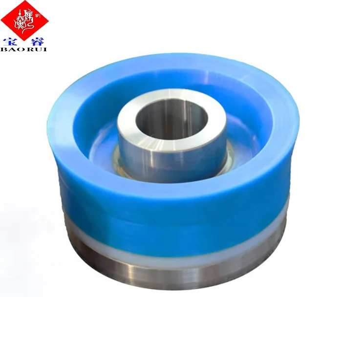
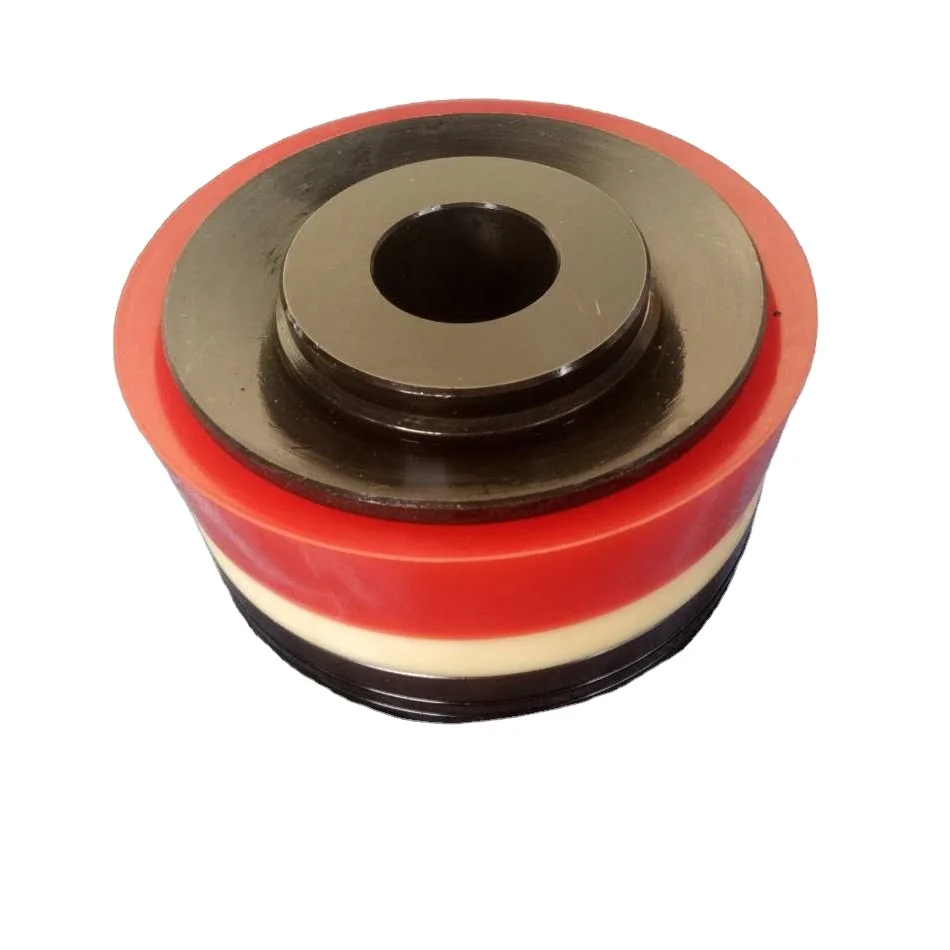
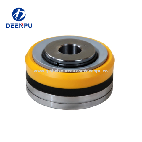
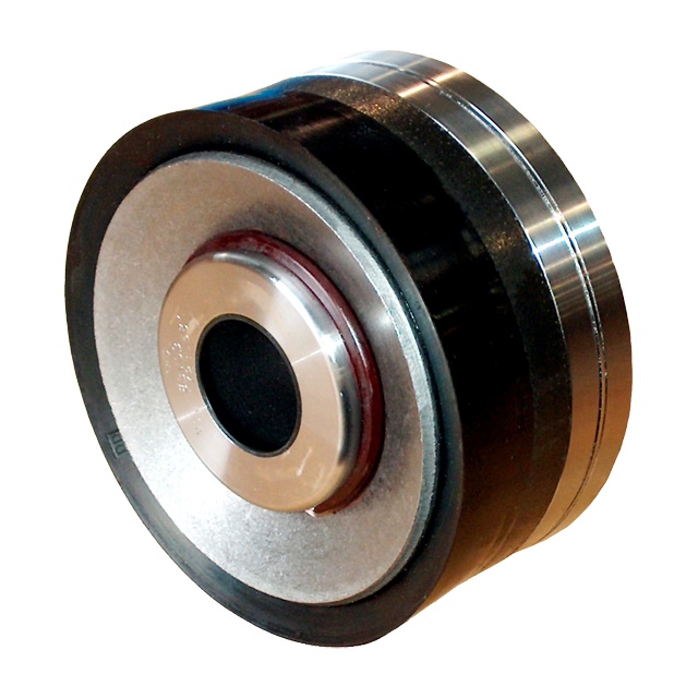
Standard pistons for crude oil service consist of cast iron or steel bodies with special patented cast iron porous chrome faced piston rings. Cast iron or steel piston bodies with nylon glass filled piston rings are furnished pumping crude oil products. Cup type pistons are furnished for pumping saltwater and rubber inserted pistons are used for slush and cementing service.
To replace pistons, remove crosshead jam nuts and power end and liquid end stuffing box glands and packing. Remove cylinder heads and pull rod, piston and liner through front of liquid end. Install new pistons, rings or cups is required. Insert pistons on to rod and into liners, oriented with front of piston toward flange end of liner. Install new liner gasket, and slip liner, piston and rod assembly into pump. Be sure to slip packing glands over rod before pushing rod thru power end stuffing box. Run crosshead jam nut onto rod as far as possible, positioned so flat face of nut will bear upon face of crosshead. Run rod into crosshead until jam nut touches crosshead, then tighten jam nut against crosshead. Be sure all mating surfaces are dry and clean before tightening nuts against pistons or crossheads. Note: torque all nuts holding pistons to rod to 7.200 in.-lbs.
Holding liner in place, roll pump one complete revolution to verify that piston is centered in the liner (end of cast iron piston may stroke out of liner), and adjust as necessary by repositioning the crosshead jam nut on the rod. Once centered, install the packing, glands, and cylinder heads. (See instructions for tightening liner set screws below.) Slush type pistons generally require more frequent attention than other types of pistons.
standard liners for crude oil service are cast iron. Liners for saltwater service are corrosion resistant material. Hardened steel liners are recommended for slush pump service. Always use new gaskets when changing liners.
There are four Liner Set Screws with jam nuts in each cylinder head. These are to hold the liner against the liner gasket. When installing cylinder head, back the liner set screws out a little and then tighten all nuts on cylinder head studs first. Be sure to work around the cylinder head from nut to nut until all are tightened evenly. Then tighten set screws against the liner, torque to 2880 in.-lbs. with the exception of Fig. 1849 pumps which are torqued to 2400 in.-lbs. again working evenly. Lastly, tighten the jam nuts on these set screws. Be sure that packing or lead gasket is in the cupped space on underside of jam nut.
Standard equipment for crude oil service consists of hardened and ground steel wing guided valves and seats. Bronze wing guided valves and seats are usually furnished for fresh or saltwater service. Tops of valve stems are slotted so that valve can be rotated in the pump to regrind valve and seat faces with grinding compound. When worn too badly, they can be removed and faced off in a lathe.
Slush pump valves require frequent replacement of rubber inserts due to the very abrasive material being pumped. Valves and seats should be inspected before starting and when finishing any drilling job. When replacing valve seats, clean valve seat and mating taper in liquid end with a cleaner that does not leave an oil film or residue. Wipe with a clean, dry rag.
Note: If the pump is EVER overloaded (loaded above maximum recommended published pressures) or if a stud EVER fails for any reason whatsoever, REPLACE ALL STUDS IN THE LIQUID BODY BEFORE USING THE PUMP AGAIN.
Pumps are equipped with O-Ring gaskets for valve covers, cylinder heads, and stuffing boxes, and with flat fiber gaskets for suction and discharge flanges. Separate lantern rings and ""tattle-tale"" packing is furnished as gaskets for liners in recently manufactured slush fitted pumps, while pumps fitted for other applications are equipped with spacers and flat fiber liner gaskets. Always be sure that all gasket surfaces are smooth and dry and free of any particles which would scratch or otherwise interfere with efficient operation of the gasket.
Piston displacement and recommended working pressure for continuous duty and with various size liners are shown in the current GASO catalog. When pumping relatively incompressible liquids, volumetric efficiency of pump when valves and liners and pistons are in good shape should be from 95% to 96%. If actual output of pump does not equal 95% of displacement figures shown at the respective speeds, cause o£ trouble may be foreign matter lodged under valve, bad valve facing, worn liners, worn piston rings, or blown liner gasket. Too small a suction line may also be cause of shortage. SUCTION LINES -- (REFER TO DIAGRAM)
Flush suction lines thoroughly before starting pump. Always provide ample capacity suction lines to the pump. This is the first requisite when installing a GASO pump. The pump cannot function properly if an inadequate quantity of fluid is furnished it. For suction lines leading directly to the pump, select a size line so that the velocity of the fluid will not exceed 12 feet per second, or one that is two sizes larger than the pump suction connection, whichever gives the slower line velocity. The last to to 15 feet of this line is preferably flexible hose and should always be connected to the pump inlet with an eccentric reducer (with straight portion on top). Always size ""headers"" feeding more than one pump so that the maximum velocity in the header with all pumps running will not exceed 1 foot per second.
NEVER USE PLUG-TYPE VALVES IN A SUCTION LINE. USE FULL OPENING VALVES. Keep the number of turns to a minimum. When turns are required, use long radius ells. In pumping gasoline or light volatile liquids such as butane and propane, design your system so that the positive suction head at the pump is at least 35 pounds per square inch (psi) above the vapor pressure of the fluid. When pumping water or average crude oils, 10 to 15 psi gauge pressure at the pump will usually be sufficient if pump speed does not exceed 54 RPM. If pump is running at higher speeds, provide for a minimum additional pressure of 15 psi at the pump inlet. Always connect to two sides of pumps with multiple suction inlets. This will help insure proper filling of the pump. If unable to connect to two sides, use a properly sized suction stabilizer, mounted and charged according to instructions with stabilizer.


 8613371530291