
mud pump assembled piston quotation

A wide variety of mud pump rubber piston assembly options are available to you, such as 1 year, not available.You can also choose from new, mud pump rubber piston assembly,As well as from energy & mining, construction works , and machinery repair shops. and whether mud pump rubber piston assembly is 1.5 years, 6 months, or unavailable.

Customers said they wanted long-lasting, easy-to-use pistons, and we delivered. Made from domestically sourced steel, GD Energy Products’ pistons feature proprietary bonded inserts and innovative geometry to deliver significantly longer life. This field proven design meets API Standards, and comes with our “Ready Inventory” promise that we’ll have it in stock, when you need it.
Our pistons, along with our new valves and seats, are designed for use in GD Energy Products PZ, F-Series, Bomco, HHA, Emsco and National 12P lines of triplex drilling pumps. Let GD Energy Products be your one-stop shop for your whole fleet of pumps.

Mud Pump Pistons are made of high hardness alloy steel, and they are wear-resistant, anti-corrosive and anti-distortion after heat treatment. The seal of the piston can be made of polyurethane, polyether material and it can be also made of thiakol rubber.
The RRP PINNACLE ASSEMBLED PISTON also known as Replaceable Rubber Piston or Supreme Piston is designed for use in the most demanding applications. The replaceable seal element is manufactured from a specially formulated elastomeric compound designed to be resistant to most chemical fluid found in the drilling industry today. These pistons can also be used in conditions where elevated temperatures can be problematic to other types of pistons in the market. The fabric anti-extrusion device on the piston is constructed from proprietary materials utilizing well researched process to reduce the extrusion of the rubber even at the pump’s maximum pressure rating.
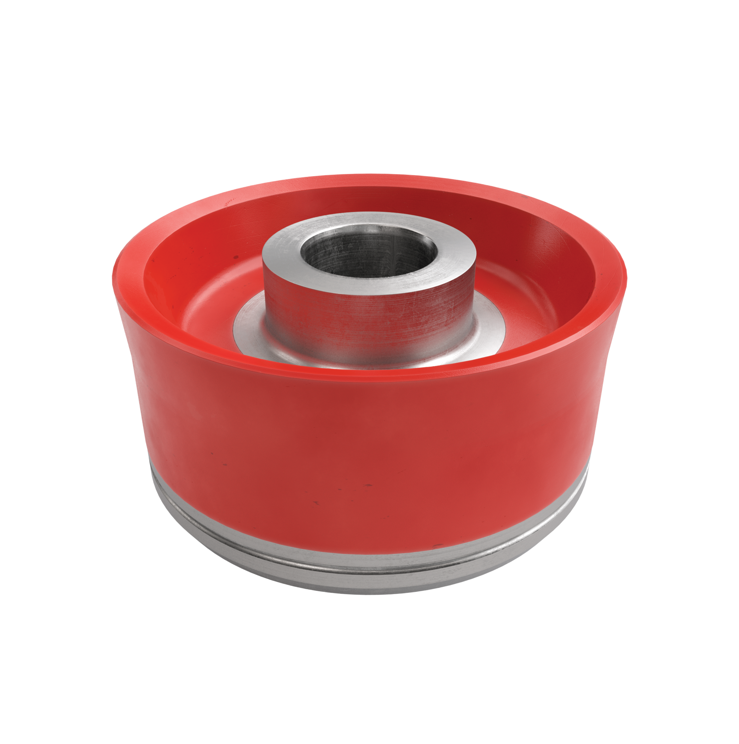
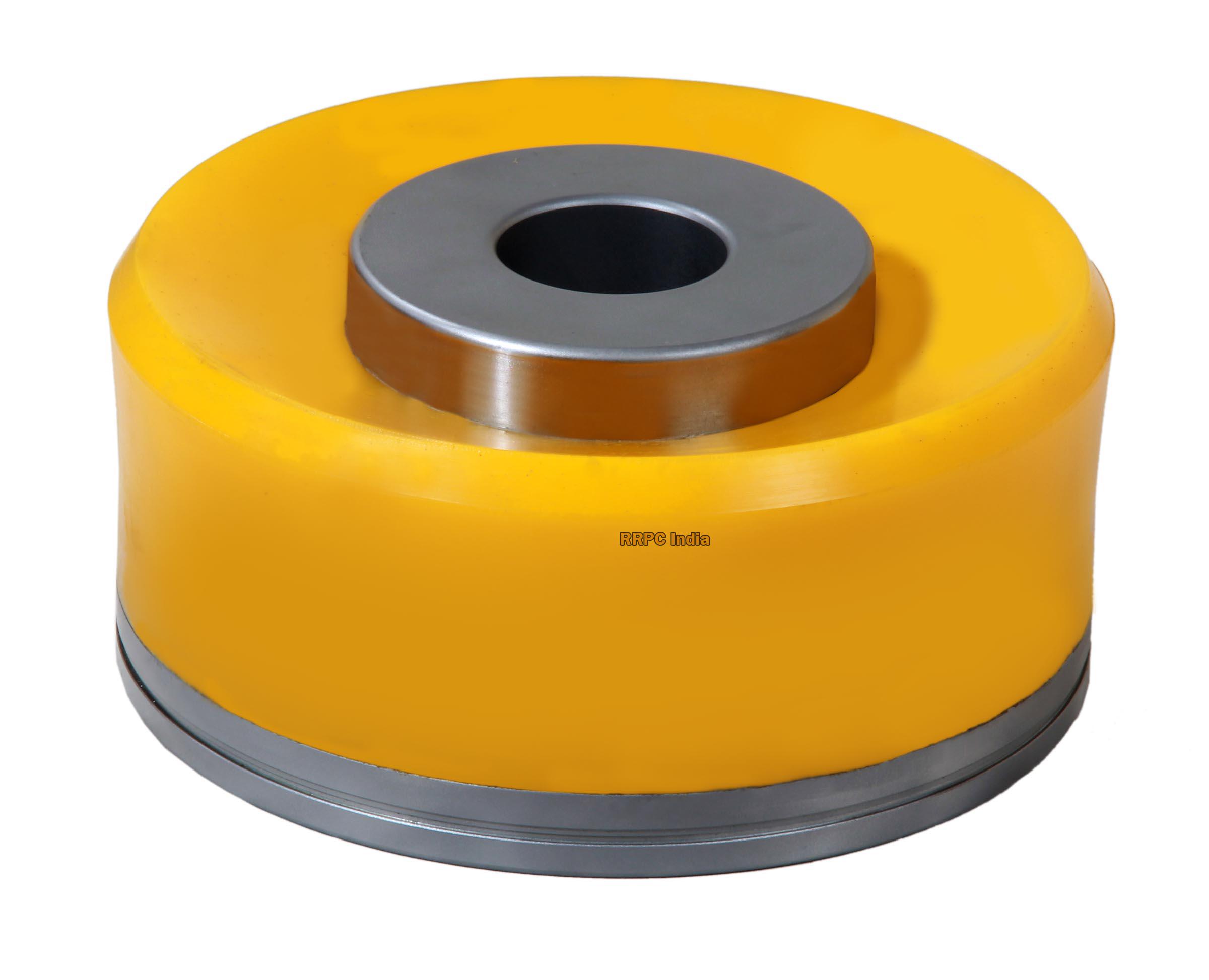
The piston reciprocates on the cylinder liner of the mud pump to provide discharge pressure for the mud pump. Piston Hub, the material used is ASTM5140 or ASTM4140, the premium forged steel. The piston has single action, double action, single action vulcanization, and double action vulcanization piston
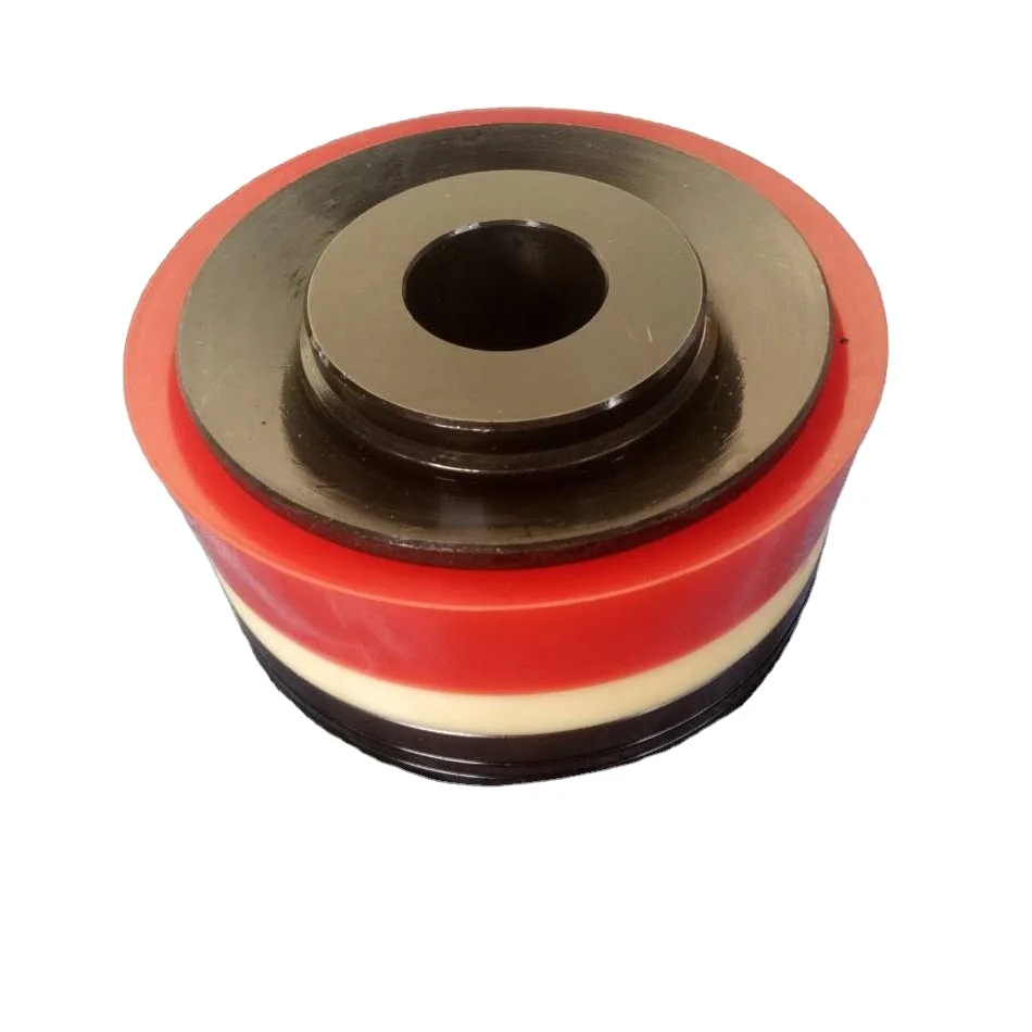
Assembled and integrated, The assembled piston includes Piston Hubs, piston rubber, Piston Plate, and Snap Ring. Piston rubber materials include polyurethane, nitrile rubber, and HNBR.

Whether onshore or offshore, well drilling sites rely on a multitude of systems to successfully perform the drilling operation. The mud pump is a key component tasked with circulating drilling fluid under high pressure downhole. The mud pump can be divided into two key sections: the power end or crosshead and the fluid end. Proper alignment of the pump’s crosshead to the fluid end liner is necessary to maximizing piston and liner life. Misalignment contributes to
accelerated wear on both the piston and the liner, and replacing these components requires downtime of the pump. Traditional methods of inspecting alignment range from using uncalibrated wooden rods, Faro Arms and micrometers to check the vertical and horizontal alignment of the piston rod OD to the piston liner ID. These are time consuming and cumbersome techniques that are ultimately not well suited to troubleshoot and solve alignment issues.
A “Mud Pump Laser Alignment Kit” enables you to measure where the piston will run through the liner at various positions along the pump’s stroke. It will also project a laser centerline from the fluid end back towards the rear power end of the pump that can be used to determine how much shimming is required to correct any alignment issues. The kit can include either a 2-Axis receiver or a 4-Axis which accepts the laser beam and documents where it falls on the active surface of the receiver. The 4-Axis receiver can decrease alignment time by as much as 50% as it will measure angularity as well as X and Y while the 2-Axis does not and will need multiple measurement locations to get the same information. In addition, the alignment system is a non-intrusive service requiring the removal of only the piston rod which allows for much quicker service and less down time on the pump. As the mud pumps in question are located globally both on and offshore, having a small, portable system is another great advantage. Our recommendation would be Pinpoint laser System’s “Mud Pump Alignment Kit”. They are being used by many of the leading repair service companies and have been their main alignment tool for over 15 years. Manufacturers are also utilizing these for new pump set-up.

Providing you the best range of Rod And Clamps, Valves And Seats, Piston Assembly, Liners and Rubberized Spares Parts with effective & timely delivery.
EMCON” screens are designed to maximize solids removal capabilities while significantly reducing costs associated with drilling fluid and disposal. The use of EMCON screens lowers the percentage of drilled solids in the mud system. Less dilution is required, decreasing total drilling fluid requirements and disposal costs. Cleaner drilling fluid will decrease down hole problems which can adversely affect drilling time. All the benefits of clean drilling fluid lead to one end result.
EMCON” Piston Rubber Assemblies are available as a kit comprising Piston Rubber, End Plate & Snap Ring for field replacement.We manufacture replacement screen for following - Derrick, Kemtron, Brandt, MI-Swaco etc
EMCON” offers very high quality and precision machined sleeved bi-metallic liners finished to relevant API dimensions. They are available for various pumps, manufactured by Oil Well, National, Gardner Denver, Omega, Ellis Williums, Bournedrill and others. They are available in different sizes ranging from 5" to 7.1/2" diameter. Accurate mirror finish at inside diameter of the liner ensures very high lives for the Pistons.

The piston is one of the parts that most easily become worn out and experience failure in mud pumps for well drilling. By imitating the body surface morphology of the dung beetle, this paper proposed a new type (BW-160) of mud pump piston that had a dimpled shape in the regular layout on the piston leather cup surface and carried out a performance test on the self-built test rig. Firstly, the influence of different dimple diameters on the service life of the piston was analyzed. Secondly, the analysis of the influence of the dimple central included angle on the service life of the piston under the same dimple area density was obtained. Thirdly, the wear of the new type of piston under the same wear time was analyzed. The experimental results indicated that the service life of the piston with dimples on the surface was longer than that of L-Standard pistons, and the maximum increase in the value of service life was 92.06%. Finally, the Workbench module of the software ANSYS was used to discuss the wear-resisting mechanism of the new type of piston.
The mud pump is the “heart” of the drilling system [1]. It has been found that about 80% of mud pump failures are caused by piston wear. Wear is the primary cause of mud pump piston failure, and improving the wear-resisting performance of the piston-cylinder friction pair has become the key factor to improve the service life of piston.
Most of the researchers mainly improve the service life of piston through structural design, shape selection, and material usage [1, 2]. However, the structure of mud pump piston has been essentially fixed. The service life of piston is improved by increasing piston parts and changing the structures of the pistons. However, the methods have many disadvantages, for example, complicating the entire structure, making piston installation and change difficult, increasing production and processing costs, and so on. All piston leather cup lips use rubber materials, and the material of the root part of the piston leather cup is nylon or fabric; many factors restrict piston service life by changing piston materials [3]. Improving the component wear resistance through surface texturing has been extensively applied in engineering. Under multiple lubricating conditions, Etsion has studied the wear performance of the laser surface texturing of end face seal and reciprocating automotive components [4–6]. Ren et al. have researched the surface functional structure from the biomimetic perspective for many years and pointed out that a nonsmooth surface structure could improve the wear resistance property of a friction pair [7, 8]. Our group has investigated the service life and wear resistance of the striped mud pump piston, and the optimal structure parameters of the bionic strip piston have improved piston service life by 81.5% [9]. Wu et al. have exploited an internal combustion engine piston skirt with a dimpled surface, and the bionic piston has showed a 90% decrease in the average wear mass loss in contrast with the standard piston [10]. Gao et al. have developed bionic drills using bionic nonsmooth theory. Compared with the ordinary drills, the bionic drills have showed a 44% increase in drilling rate and a 74% improvement in service life [11]. The present researches indicate that microstructures, like superficial dimples and stripes, contribute to constituting dynamic pressure to improve the surface load-carrying capacity and the wear resistance of the friction pair [12–21].
In nature, insects have developed the excellent wear-resistant property in the span of billions of years. For instance, the partial body surface of the dung beetle shows an irregularly dimpled textured surface with the excellent wear-resistant property that is conducive to its living environment [7, 8, 22]. The dung beetle, which is constantly active in the soil, shows a body surface dimple structure that offers superior drag reduction. These dimples effectively reduce the contact area between the body surface and the soil. Moreover, the friction force is reduced. Therefore, the dung beetle with the nonsmooth structure provides the inspiration to design the bionic mud pump piston. This paper proposed a new type of piston with dimpled morphology on its surface and conducted a comparative and experimental study of different surface dimpled shapes, thus opening up a new potential to improve the service life of the mud pump piston.
A closed-loop circulatory system was used in the test rig, which was built according to the national standard with specific test requirements. The test rig consisted of triplex single-acting mud pump, mud tank, in-and-out pipeline, reducer valve, flow meter, pressure gauge, and its principle, as shown in Figure 1. Both the pressure and working stroke of the BW-160 mud pump are smaller than those of the large-scale mud pump, but their operating principles, structures, and working processes are identical. Therefore, the test selected a relatively small BW-160 triplex single-acting mud pump piston as a research object, and the test results and conclusion were applicable to large-scale mud pump pistons. The cylinder diameter, working stroke, reciprocating motion velocity of piston, maximum flow quantity, and working pressure of the BW-160 triplex single-acting mud pump were 70 mm, 70 mm, 130 times/min, 160 L/min, and 0.8–1.2 MPa, respectively.
The mud pump used in the test consisted of water, bentonite (meeting the API standard), and quartz sand with a diameter of 0.3–0.5 mm according to actual working conditions. The specific gravity of the prepared mud was 1.306, and its sediment concentration was 2.13%. Whether mud leakage existed at the venthole in the tail of the cylinder liner of the mud pump was taken as the standard of piston failure. Observation was made every other half an hour during the test process. It was judged that the piston in the cylinder failed when mud leaked continuously; its service life was recorded, and then it was replaced with the new test piston and cylinder liner. The BW-160 mud pump is a triplex single-acting mud pump. The wear test of three pistons could be simultaneously conducted.
The mud pump piston used in the test consisted of a steel core, leather cup, pressing plate, and clamp spring. The leather cup consisted of the lip part of polyurethane rubber and the root part of nylon; the outer diameter on the front end of the piston was 73 mm, and the outer diameter of the piston tail was 70 mm, as shown in Figure 2. We proceeded in two parts during the design of the dimpled layout pattern because the piston leather cup consisted of two parts whose materials were different. The dimples at the lip part of the leather cup adopted an isosceles triangle layout pattern, and the dimples at the root part were arranged at the central part of its axial length, as shown in Figure 3(a). Dimple diameter (D, D′), distance (L), depth (h), and central included angle (α) are shown in Figure 3. The dimples on the piston surface were processed by the CNC machining center. Since then, the residual debris inside the dimples was cleaned.
Schematic of dimpled piston: (a) dimpled layout of piston, (b) dimpled array form diagram, (c) cross section view of the piston leather cup, and (d) original picture of dimpled piston.
The test program was divided into three contrast groups. The dimple depth in the test was 2.5 mm. Table 1 shows the comparison between the service life of dimpled piston with different diameters L-D1, L-D2, and L-D3 and that of the L-Standard piston. In Table 1, a comparison between the L-D4 piston with dimples at the leather cup root and the L-D2 piston is shown to study the influence of dimples at the leather cup root on the piston service life. Table 2 gives the influence of the dimple central included angle on piston service life when the dimple area density was the same by taking the L-D2 area density as a criterion. Table 3 displays a comparison of the wear patterns of pistons with different dimple diameters and L-Standard pistons under the same wear time. This object of the group test is to analyze the dimple wear pattern at the leather cup root under the existence of dimples at the roots of all leather cups.
Table 1 shows that average service lives of L-Standard, L-D1, L-D2, and L-D3 were 54.67 h, 57.17 h, 76.83 h, and 87.83 h, respectively. Therefore, the mud pump pistons with dimples provide longer service life than the L-Standard piston. As the dimple diameter increases, the piston service life was improved, and the largest percentage increase of the service life was 60.65%. The service life of the L-D4 piston was about 81.17 h, which increased by 7.94% compared with that of the L-D2 piston, indicating that the piston with dimples at the leather cup root could improve piston service life.
Figure 4 illustrates the surface wear patterns of pistons with different dimple diameters in the service life test. Figures 4(a) and 4(a′) show wear patterns on the surface of the L-Standard piston. This figure shows that intensive scratches existed in parallel arrangement on the piston leather cup surface, enabling high-pressure mud to move along the scratches from one end of the piston to the other easily, which accelerated the abrasive wear failure with the abrasive particles of the piston. Figures 4(b), 4(b′), 4(c), 4(c′), 4(d), and 4(d′) show the wear patterns of the leather cup surfaces of L-D1, L-D2, and L-D3 pistons, respectively. Figures 4(b), 4(b′), 4(c), 4(c′), 4(d), and 4(d′) show that the scratches on the leather cup surface became shallower and sparser and the surface wear patterns improved more obviously as the dimple diameter increased. If the piston leather cup surface strength was not affected to an extent as the dimple diameter increased, the reduced wear zone near the dimple would become greater and greater, indicating that the existence of dimples changed the lubricating status of the leather cup surface, their influence on nearby dimpled parts was more obvious, and they played active roles in improving the service life of the piston.
Surface wear patterns of pistons with different dimple diameters in the service life test: (a) L-Standard piston, (b) L-D1 piston, (c) L-D2 piston, and (d) L-D3 piston. (a′, b′, c′, d′) are partial enlarged pictures of (a, b, c, d).
Figure 5 displays the wear patterns of the leather cup root parts of the L-D4 and L-D2 test pistons. The wear patterns of the nylon root parts of the L-D4 pistons are fewer than those of the L-D2 pistons, as shown in Figure 5. When the leather cup squeezed out high-pressure mud as driven by the piston steel core, it experienced radial squeezing while experiencing axial wear. Therefore, the area with the most serious wear was the piston leather cup root part, and the friction force at the leather cup root was much greater than that at the other areas. The rapid wear at the root decreased the piston load-carrying capacity and then affected the service life of piston. The dimples at the piston leather cup root could reduce the wear of the piston leather cup root and improve the service life of piston.
Wear patterns of the piston leather cup root with and without dimples: (a) comparison chart of root wear of the L-D4 and L-D2 pistons, (b) partial enlarged diagram of root wear of the L-D4 piston, and (c) partial enlarged diagram of root wear of the L-D2 piston.
Table 2 indicates that the average service life of the L-S1 piston was 105.00 h, which is about twice that of the L-S2 piston (59.50 h) and was obviously improved in comparison with that of the L-D2 piston (76.83 h), indicating that, under the same dimple area density, the smaller the dimple central included angle was, that is, the closer the circumferential arrangement of dimples was, the longer the service life of the piston would be, and the increase of the maximum value of service life was 92.06%.
Figure 6 shows the surface wear patterns of the L-S1 and L-S2 test pistons. In Figures 6(a) and 6(a′), the scratches on the piston leather cup surface became sparse and shallow in the dimpled area. Figures 6(b) and 6(b′) show that the wear was slight in the area close to the dimples. The farther the scratches were from the dimpled area, the denser and deeper the scratches would be. The L-S1 piston had a small dimple central included angle, which was arranged more closely on the piston surface. The lubricating effects of oil storage in each row of dimples were overlaid very well, which was equivalent to amplifying the effect of each row of dimples in Figure 6(b), making the wear on the whole piston leather cup surface slight, preventing the entry of high-pressure mud into the frictional interface, and lengthening the service life of piston.
Wear patterns of pistons with different dimple central included angles under the same area density: (a) L-S1 piston and (b) L-S2 piston. (a′, b′) were partial enlarged pictures of (a, b).
Before all pistons have not failure, T1, T2, T3, and L-Standard experienced equal-time wear. This test set the wear time at 30 h. The piston leather cup mass was W0 before the test. After the test, the mass of the piston leather cup was W1. During the test, the wear loss of the piston leather cup was W = W0 − W1. The wear mass percentage of the test piston leather cup was calculated as φ = W/W0. The test results are shown in Table 3.
Table 3 shows that the average wear mass percentages of the L-Standard, T1, T2, and T3 pistons were 6.98%, 6.59%, 4.22%, and 3.83%, respectively. The wear mass percentages of the dimpled pistons were basically lower than those of the L-Standard piston and decreased as the dimple diameter increased. Figure 7 shows the wear patterns of the piston leather cup. The wear rules displayed in Figure 7 were similar to those displayed in Figure 4. The only difference was that the wear in Figure 7 was slighter than that in Figure 4. Based on the wear under the same time, the existence of dimples reduced the piston wear.
During the operation of the mud pump piston, the outside surface of the piston leather cup comes in contact with the inner wall of the cylinder liner and simultaneously moves to push the mud. The lip part of the piston leather cup mainly participated in the piston wear and exerted a sealing effect, while the piston root part mainly exerted centralizing and transitional effects. In the mud discharge stroke, the lip part of the piston experienced a “centripetal effect,” and a gap was generated between the lip part and the cylinder liner. The greater the contact pressure between the lip part and cylinder liner of the piston was, the smaller the gap was, and the entry of high-pressure mud into the contact surface between the piston and cylinder liner was more difficult. The piston root easily experienced squeezing under high pressure, and the smaller the equivalent stress caused by the piston root was, the more difficult the squeezing to occur. Hence, the contact pressure at the lip part of the piston and the equivalent stress at the root were analyzed, and they would provide a theoretical basis for the piston wear-resisting mechanism. The ANSYS Workbench module was used to perform a comparative analysis between the contact pressure at the lip part and the equivalent stress at the root of the three kinds of pistons (i.e., L-Standard piston, L-S1 piston, and L-D1 piston). The service life of the L-S1 piston exhibited the best improvement effect, whereas that of the L-D1 piston demonstrated the worst improvement effect. The piston adopted a 1 mm hexahedral grid, and the grid nodes and elements are as shown in Table 4.
We could obtain the contact pressure nephograms of the three pistons by analyzing the contact pressure of the lip parts of the L-Standard piston and two dimpled pistons, as shown in Figure 8.
The contact pressure nephograms of the three pistons indicate that the dimpled structure on the piston surface changed the distribution state of contact pressure. Three nodes were selected at the same position of each piston to obtain the contact pressure values. The node positions are shown in Figure 8(c), and the average pressure value of three nodes was the pressure value at the lip part of this piston. The contact pressure value of the L-Standard piston was 0.6027 MPa and that of the L-D1 and L-S1 pistons was 0.6840 MPa and 1.0994 MPa, respectively. Compared with the L-Standard piston, the contact pressure at the lip part of the L-S1 piston increased, the gap between the piston and cylinder liner became small, which could effectively prevent abrasive particles from participating in the wear and resulting in piston failure, and there was greater improvement in the service life of piston. The contact pressure of the L-D1 piston did not increase too much, and the degree of improvement of the piston service life was not obvious.
An equivalent stress analysis of the root parts of the L-Standard piston and two dimpled pistons was conducted to obtain the equivalent stress nephograms of the three pistons, as shown in Figure 9.
The equivalent stress nephograms of the three pistons show that the root of the L-Standard piston bore great stress and was easily squeezed, which accelerated piston wear and reduced piston service life. The dimpled structure could reduce the equivalent stress at the piston root and lengthen piston service life. Three nodes were selected in the same root positions of the three pistons. Their positions are as shown in Figure 9(c). The average value of the equivalent stresses of the three nodes was the equivalent stress value at the root of this piston. The equivalent stress value of the L-Standard piston was 0.1093 MPa, that of the L-D1 piston was 0.1066 MPa, and that of the L-S1 piston was 0.0922 MPa. The dimpled structure of the L-S1 piston could reduce the equivalent stress at the root and reduce the occurrence of root squeezing wear. The equivalent stress value of L-D1 did not decrease too much, and the degree of improvement of the piston service life was not obvious.
The lubricating oil on the mud pump piston surface could reduce the wear of piston and cylinder liner and improve the service life of pistons with the reciprocating movement. The lubricating oil would eventually run off and lose lubricating effect, which would result in piston wear. The finite element fluid dynamics software CFX was used to establish the fluid domain model of the dimpled and L-Standard pistons and analyze the lubricating state on the piston surface. The piston surface streamlines are shown in Figure 10. This figure shows that the lubricating fluid did not experience truncation or backflow phenomenon when passing the surface of the L-Standard piston. When the lubricating fluid flowed through the surface of the dimpled piston, it presented a noncontinuous process. Its flow velocity at the dimpled structure slowed down obviously because it was blocked by the dimpled structure.
Figure 11 shows the piston cross section streamline. This figure shows that the existence of dimples changed the distribution status of the lubricating flow fields on the contact surface between the piston and cylinder liner. The lubricating oil entered the dimpled structure in a large quantity, and the flow velocity slowed down. The dimpled structure on the piston surface enlarged the storage space of the lubricating oil and made it difficult for the lubricating oil inside the dimpled structure to be taken away by the cylinder liner to improve the lubricating conditions of the friction pair interface, reduce the frictional resistance between the piston and cylinder liner, reduce wear, and improve the piston service life.
When the piston moved in the cylinder liner, a small quantity of solid particles in mud entered gap of piston and cylinder liner and participated in abrasion. The dimpled structure on the piston surface could store some abrasive particles (as shown in Figure 6(a′)) during the piston wear process to prevent these particles from scratching the piston and cylinder liner and generating gullies, thus avoiding secondary damage to the piston and cylinder liner and improving the piston service life.
This paper presented a dimpled-shape mud pump piston; that is, the piston leather cup surface had a dimpled array morphology in regular arrangement. The experimental results can provide the basic data for design engineering of the mud pump piston with a long service life. The comparative analyses of service life and wear patterns for dimpled mud pump pistons and L-Standard pistons were conducted. The main results and conclusions were summarized as follows:(1)The service life of the mud pump piston with dimpled morphology on the surface improved in comparison with that of the L-Standard piston, and the service life increase percentages were from 4.57% to 92.06%.(2)The piston service life would increase with the dimple diameter under the same dimpled arrangement pattern, and the maximum increase in the value of service life was 60.65%.(3)The service life of the piston with dimples increased by 7.94% in comparison with that with none.(4)Under the same dimpled arrangement patterns and area densities, the tighter and closer the dimples were arranged on the piston surface, the longer the service life of piston was, and the maximum increase in the value of service life was 92.06%.(5)Under the same wear time, the wear of the dimpled piston slightly decreased in comparison with that of the L-Standard piston, and the minimum value of wear mass percentage was 3.83%.(6)The dimpled shape could not only change the stress state of the piston structure, improve piston wear resistance, and reduce root squeezing, but also increase oil storage space, improve lubricating conditions, and enable the accommodation of some abrasive particles. Furthermore, the dimpled shape was the key factor for the service life improvement of the mud pump piston.

Hole Products offers a complete line of American Manufacturing and FMC Technologies® "Bean" piston pumps and interchangeable pump parts for use in a variety of mud pumping and drilling applications. All piston pumps are designed for continuous duty industrial applications and are capable of handling even the most abrasive drilling fluids. Piston pumps feature simple designs that incorporate less wearable parts and provide for ease of service. Piston pumps are available in duplex, triplex, and quadruplex configurations with a wide range of capacities and pressures. Pumps can incorporate ductile iron, aluminum bronze, and other materials as required. Please contact your Hole Products representative for specific pump performance details and ordering assistance.
F04B15/02—Pumps adapted to handle specific fluids, e.g. by selection of specific materials for pumps or pump parts the fluids being viscous or non-homogeneous
A quintuplex mud pump has a crankshaft supported in the pump by external main bearings. The crankshaft has five eccentric sheaves, two internal main bearing sheaves, and two bull gears. Each of the main bearing sheaves supports the crankshaft by a main bearing. One main bearing sheave is disposed between second and third eccentric sheaves, while the other main bearing sheave is disposed between third and fourth eccentric sheaves. One bull gear is disposed between the first and second eccentric sheaves, while the second bull gear is disposed between fourth and fifth eccentric sheaves. A pinion shaft has pinion gears interfacing with the crankshaft"s bull gears. Connecting rods on the eccentric sheaves use roller bearings and transfer rotational movement of the crankshaft to pistons of the pump"s fluid assembly.
Triplex mud pumps pump drilling mud during well operations. An example of a typical triplex mud pump 10 shown in FIG. 1A has a power assembly 12, a crosshead assembly 14, and a fluid assembly 16. Electric motors (not shown) connect to a pinion shaft 30 that drives the power assembly 12. The crosshead assembly 14 converts the rotational movement of the power assembly 12 into reciprocating movement to actuate internal pistons or plungers of the fluid assembly 16. Being triplex, the pump"s fluid assembly 16 has three internal pistons to pump the mud.
As shown in FIG. 1B, the pump"s power assembly 14 has a crankshaft 20 supported at its ends by double roller bearings 22. Positioned along its intermediate extent, the crankshaft 20 has three eccentric sheaves 24-1 . . . 24-3, and three connecting rods 40 mount onto these sheaves 24 with cylindrical roller bearings 26. These connecting rods 40 connect by extension rods (not shown) and the crosshead assembly (14) to the pistons of the pump"s fluid assembly 16.
In addition to the sheaves, the crankshaft 20 also has a bull gear 28 positioned between the second and third sheaves 24-2 and 24-3. The bull gear 28 interfaces with the pinion shaft (30) and drives the crankshaft 20"s rotation. As shown particularly in FIG. 1C, the pinion shaft 30 also mounts in the power assembly 14 with roller bearings 32 supporting its ends. When electric motors couple to the pinion shaft"s ends 34 and rotate the pinion shaft 30, a pinion gear 38 interfacing with the crankshaft"s bull gear 28 drives the crankshaft (20), thereby operating the pistons of the pump"s fluid assembly 16.
When used to pump mud, the triplex mud pump 10 produces flow that varies by approximately 23%. For example, the pump 10 produces a maximum flow level of about 106% during certain crankshaft angles and produces a minimum flow level of 83% during other crankshaft angles, resulting in a total flow variation of 23% as the pump"s pistons are moved in differing exhaust strokes during the crankshaft"s rotation. Because the total flow varies, the pump 10 tends to produce undesirable pressure changes or “noise” in the pumped mud. In turn, this noise interferes with downhole telemetry and other techniques used during measurement-while-drilling (MWD) and logging-while-drilling (LWD) operations.
In contrast to mud pumps, well-service pumps (WSP) are also used during well operations. A well service pump is used to pump fluid at higher pressures than those used to pump mud. Therefore, the well service pumps are typically used to pump high pressure fluid into a well during frac operations or the like. An example of a well-service pump 50 is shown in FIG. 2. Here, the well service pump 50 is a quintuplex well service pump, although triplex well service pumps are also used. The pump 50 has a power assembly 52, a crosshead assembly 54, and a fluid assembly 56. A gear reducer 53 on one side of the pump 50 connects a drive (not shown) to the power assembly 52 to drive the pump 50.
As shown in FIG. 3, the pump"s power assembly 52 has a crankshaft 60 with five crankpins 62 and an internal main bearing sheave 64. The crankpins 62 are offset from the crankshaft 60"s axis of rotation and convert the rotation of the crankshaft 60 in to a reciprocating motion for operating pistons (not shown) in the pump"s fluid assembly 56. Double roller bearings 66 support the crankshaft 60 at both ends of the power assembly 52, and an internal double roller bearing 68 supports the crankshaft 60 at its main bearing sheave 64. One end 61 of the crankshaft 60 extends outside the power assembly 52 for coupling to the gear reducer (53; FIG. 2) and other drive components.
As shown in FIG. 4A, connecting rods 70 connect from the crankpins 62 to pistons or plungers 80 via the crosshead assembly 54. FIG. 4B shows a typical connection of a connecting rod 70 to a crankpin 62 in the well service pump 50. As shown, a bearing cap 74 fits on one side of the crankpin 62 and couples to the profiled end of the connecting rod 70. To reduce friction, the connection uses a sleeve bearing 76 between the rod 70, bearing cap 74, and crankpin 62. From the crankpin 62, the connecting rod 70 connects to a crosshead 55 using a wrist pin 72 as shown in FIG. 4A. The wrist pin 72 allows the connecting rod 70 to pivot with respect to the crosshead 55, which in turn is connected to the plunger 80.
In use, an electric motor or an internal combustion engine (such as a diesel engine) drives the pump 50 by the gear reducer 53. As the crankshaft 60 turns, the crankpins 62 reciprocate the connecting rods 70. Moved by the rods 70, the crossheads 55 reciprocate inside fixed cylinders. In turn, the plunger 80 coupled to the crosshead 55 also reciprocates between suction and power strokes in the fluid assembly 56. Withdrawal of a plunger 80 during a suction stroke pulls fluid into the assembly 56 through the input valve 82 connected to an inlet hose or pipe (not shown). Subsequently pushed during the power stroke, the plunger 80 then forces the fluid under pressure out through the output valve 84 connected to an outlet hose or pipe (not shown).
In contrast to using a crankshaft for a quintuplex well-service pump that has crankpins 62 as discussed above, another type of quintuplex well-service pump uses eccentric sheaves on a direct drive crankshaft. FIG. 4C is an isolated view of such a crankshaft 90 having eccentric sheaves 92-1 . . . 92-5 for use in a quintuplex well-service pump. External main bearings (not shown) support the crankshaft 90 at its ends 96 in the well-service pumps housing (not shown). To drive the crankshaft 90, one end 91 extends beyond the pumps housing for coupling to drive components, such as a gear box. The crankshaft 90 has five eccentric sheaves 92-1 . . . 92-5 for coupling to connecting rods (not shown) with roller bearings. The crankshaft 90 also has two internal main bearing sheaves 94-1, 94-2 for internal main bearings used to support the crankshaft 90 in the pump"s housing.
In the past, quintuplex well-service pumps used for pumping frac fluid or the like have been substituted for mud pumps during drilling operations to pump mud. Unfortunately, the well-service pump has a shorter service life compared to the conventional triplex mud pumps, making use of the well-service pump as a mud pump less desirable in most situations. In addition, a quintuplex well-service pump produces a great deal of white noise that interferes with MWD and LWD operations, further making the pump"s use to pump mud less desirable in most situations. Furthermore, the well-service pump is configured for direct drive by a motor and gear box directly coupling on one end of the crankshaft. This direct coupling limits what drives can be used with the pump. Moreover, the direct drive to the crankshaft can produce various issues with noise, balance, wear, and other associated problems that make use of the well-service pump to pump mud less desirable.
One might expect to provide a quintuplex mud pump by extending the conventional arrangement of a triplex mud pump (e.g., as shown in FIG. 1B) to include components for two additional pistons or plungers. However, the actual design for a quintuplex mud pump is not as easy as extending the conventional arrangement, especially in light of the requirements for a mud pump"s operation such as service life, noise levels, crankshaft deflection, balance, and other considerations. As a result, acceptable implementation of a quintuplex mud pump has not been achieved in the art during the long history of mud pump design.
What is needed is an efficient mud pump that has a long service life and that produces low levels of white noise during operation so as not to interfere with MWD and LWD operations while pumping mud in a well.
A quintuplex mud pump is a continuous duty, reciprocating plunger/piston pump. The mud pump has a crankshaft supported in the pump by external main bearings and uses internal gearing and a pinion shaft to drive the crankshaft. Five eccentric sheaves and two internal main bearing sheaves are provided on the crankshaft. Each of the main bearing sheaves supports the intermediate extent of crankshaft using bearings. One main bearing sheave is disposed between the second and third eccentric sheaves, while the other main bearing sheave is disposed between the third and fourth eccentric sheaves.
One or more bull gears are also provided on the crankshaft, and the pump"s pinion shaft has one or more pinion gears that interface with the one or more bull gears. If one bull gear is used, the interface between the bull and pinion gears can use herringbone or double helical gearing of opposite hand to avoid axial thrust. If two bull gears are used, the interface between the bull and pinion gears can use helical gearing with each having opposite hand to avoid axial thrust. For example, one of two bull gears can be disposed between the first and second eccentric sheaves, while the second bull gear can be disposed between fourth and fifth eccentric sheaves. These bull gears can have opposite hand. The pump"s internal gearing allows the pump to be driven conventionally and packaged in any standard mud pump packaging arrangement. Electric motors (for example, twin motors made by GE) may be used to drive the pump, although the pump"s rated input horsepower may be a factor used to determine the type of motor.
Connecting rods connect to the eccentric sheaves and use roller bearings. During rotation of the crankshaft, these connecting rods transfer the crankshaft"s rotational movement to reciprocating motion of the pistons or plungers in the pump"s fluid assembly. As such, the quintuplex mud pump uses all roller bearings to support its crankshaft and to transfer crankshaft motion to the connecting rods. In this way, the quintuplex mud pump can reduce the white noise typically produced by conventional triplex mud pumps and well service pumps that can interfere with MWD and LWD operations.
Turning to the drawings, a quintuplex mud pump 100 shown in FIGS. 5 and 6A-6B has a power assembly 110, a crosshead assembly 150, and a fluid assembly 170. Twin drives (e.g., electric motors, etc.) couple to ends of the power assembly"s pinion shaft 130 to drive the pump"s power assembly 110. As shown in FIGS. 6A-6B, internal gearing within the power assembly 110 converts the rotation of the pinion shaft 130 to rotation of a crankshaft 120. The gearing uses pinion gears 138 on the pinion shaft 130 that couple to bull gears 128 on the crankshaft 120 and transfer rotation of the pinion shaft 130 to the crankshaft 120.
For support, the crankshaft 120 has external main bearings 122 supporting its ends and two internal main bearings 127 supporting its intermediate extent in the assembly 110. As best shown in FIG. 6A, rotation of the crankshaft 120 reciprocates five independent connecting rods 140. Each of the connecting rods 140 couples to a crosshead 160 of the crosshead assembly 150. In turn, each of the crossheads 160 converts the connecting rod 40"s movement into a reciprocating movement of an intermediate pony rod 166. As it reciprocates, the pony rod 166 drives a coupled piston or plunger (not shown) in the fluid assembly 170 that pumps mud from an intake manifold 192 to an output manifold 198. Being quintuplex, the mud pump 100 has five such pistons movable in the fluid assembly 170 for pumping the mud.
Shown in isolated detail in FIG. 7, the crankshaft 120 has five eccentric sheaves 124-1 through 124-5 disposed thereon. Each of these sheaves can mechanically assemble onto the main vertical extent of the crankshaft 120 as opposed to being welded thereon. During rotation of the crankshaft 120, the eccentric sheaves actuate in a firing order of 124-1, 3, 5, 2 and 4 to operate the fluid assembly"s pistons (not shown). This order allows the crankshaft 120 to be assembled by permitting the various sheaves to be mounted thereon. Preferably, each of the eccentric sheaves 124-1 . . . 124-5 is equidistantly spaced on the crankshaft 120 for balance.
The cross-section in FIG. 10A shows a crosshead 160 for the quintuplex mud pump. The end of the connecting rod 140 couples by a wrist pin 142 and bearing 144 to a crosshead body 162 that is movable in a crosshead guide 164. A pony rod 166 coupled to the crosshead body 162 extends through a stuffing box gasket 168 on a diaphragm plate 169. An end of this pony rod 166 in turn couples to additional components of the fluid assembly (170) as discussed below.
The cross-section in FIG. 10B shows portion of the fluid assembly 170 for the quintuplex mud pump. An intermediate rod 172 has a clamp 174 that couples to the pony rod (166; FIG. 10A) from the crosshead assembly 160 of FIG. 10A. The opposite end of the rod 172 couples by another clamp to a piston rod 180 having a piston head 182 on its end. Although a piston arrangement is shown, the fluid assembly 170 can use a plunger or any other equivalent arrangement so that the terms piston and plunger can be used interchangeably herein. Moved by the pony rod (166), the piston head 182 moves in a liner 184 communicating with a fluid passage 190. As the piston 182 moves, it pulls mud from a suction manifold 192 through a suction valve 194 into the passage 190 and pushes the mud in the passage 190 to a discharge manifold 198 through a discharge valve 196.
As noted previously, a triplex mud pump produces a total flow variation of about 23%. Because the present mud pump 100 is quintuplex, the pump 100 offers a lower variation in total flow, making the pump 100 better suited for pumping mud and producing less noise that can interfere with MWD and LWD operations. In particular, the quintuplex mud pump 100 can produce a total flow variation as low as about 7%. For example, the quintuplex mud pump 100 can produce a maximum flow level of about 102% during certain crankshaft angles and can produce a minimum flow level of 95% during other crankshaft angles as the pump"s five pistons move in their differing strokes during the crankshaft"s rotation. Being smoother and closer to ideal, the lower total flow variation of 7% produces less pressure changes or “noise” in the pumped mud that can interfere with MWD and LWD operations.
Although a quintuplex mud pump is described above, it will be appreciated that the teachings of the present disclosure can be applied to multiplex mud pumps having at least more than three eccentric sheaves, connecting rods, and fluid assembly pistons. Preferably, the arrangement involves an odd number of these components so such mud pumps may be septuplex, nonuplex, etc. For example, a septuplex mud pump according to the present disclosure may have seven eccentric sheaves, connecting rods, and fluid assembly pistons with at least two bull gears and at least two bearing sheaves on the crankshaft. The bull gears can be arranged between first and second eccentric sheaves and sixth and seventh eccentric sheaves on the crankshaft. The internal main bearings supporting the crankshaft can be positioned between third and fourth eccentric sheaves and the fourth and fifth eccentric sheaves on the crankshaft.
a crankshaft rotatably supported in the pump by a plurality of main bearings, the crankshaft having five eccentric sheaves and a first bull gear disposed thereon, the main bearings including a first internal main bearing sheave disposed between the second and third eccentric sheaves and including a second internal main bearing sheave disposed between the third and fourth eccentric sheaves;
a pinion shaft for driving the crankshaft, the pinion shaft rotatably supported in the pump and having a first pinion gear interfacing with the first bull gear on the crankshaft; and
6. A pump of claim 1, wherein the crankshaft comprises a second bull gear disposed thereon, and wherein the pinion shaft comprises a second pinion gear disposed thereon and interfacing with the second bull gear.
7. A pump of claim 6, wherein the first bull gear is disposed between the first and second eccentric sheaves, and wherein the second bull gear is disposed between the fourth and fifth eccentric sheaves.
8. A pump of claim 6, wherein the five eccentric sheaves, the first and second internal main bearing sheaves, and the first and second bull gears are equidistantly spaced from one another on the crankshaft.
9. A pump of claim 6, wherein the first and second pinion gears comprise helical gearing of opposite hand, and wherein the first and second bull gears comprise helical gearing of opposite hand complementary to the pinion gears.
a crankshaft rotatably supported in the pump by two external main bearings and two internal main bearings, the crankshaft having five eccentric sheaves, two internal main bearing sheaves for the internal main bearings, and at least one bull gear disposed thereon;
13. A pump of claim 11, wherein a first of the main bearing sheaves is disposed between the second and third eccentric sheaves, and wherein a second of the main bearing sheaves is disposed between the third and fourth eccentric sheaves.
16. A pump of claim 11, wherein the at least one bull gear comprises first and second bull gears disposed on the crankshaft, and wherein the at least one pinion gear comprises first and second pinion gears disposed on the crankshaft.
17. A pump of claim 16, wherein the first bull gear is disposed between the first and second eccentric sheaves, and wherein the second bull gear is disposed between the fourth and fifth eccentric sheaves.
18. A pump of claim 16, wherein the five eccentric sheaves, the two internal main bearing sheaves, and the first and second bull gears are equidistantly spaced from one another on the crankshaft.
19. A pump of claim 16, wherein the first and second pinion gears comprise helical gearing of opposite hand, and wherein the first and second bull gears comprise helical gearing of opposite hand complementary to the pinion gears.
a crankshaft rotatably supported in the pump by a plurality of main bearings, the crankshaft having five eccentric sheaves and first and second bull gears disposed thereon, the first bull gear disposed between the first and second eccentric sheaves, the second bull gear disposed between the fourth and fifth eccentric sheaves;
a pinion shaft for driving the crankshaft, the pinion shaft rotatably supported in the pump, the pinion shaft having a first pinion gear interfacing with the first bull gear on the crankshaft and having a second pinion gear interfacing with the second bull gear on the crankshaft; and
26. A pump of claim 21, wherein the main bearings include first and second internal main gearing sheaves disposed on the crankshaft, and wherein the five eccentric sheaves, the two internal main bearing sheaves, and the first and second bull gears are equidistantly spaced from one another on the crankshaft.
27. A pump of claim 21, wherein the first and second pinion gears comprise helical gearing of opposite hand, and wherein the first and second bull gears comprise helical gearing of opposite hand complementary to the pinion gears.
a crankshaft rotatably supported in the pump by a plurality of main bearings, the crankshaft having five eccentric sheaves and first and second bull gears disposed thereon, the main bearings including two internal main bearing sheaves disposed on the crankshaft, wherein the five eccentric sheaves, the two internal main bearing sheaves, and the first and second bull gears are equidistantly spaced from one another on the crankshaft;
a pinion shaft for driving the crankshaft, the pinion shaft rotatably supported in the pump, the pinion shaft having a first pinion gear interfacing with the first bull gear on the crankshaft and having a second pinion gear interfacing with the second bull gear on the crankshaft; and
34. A pump of claim 29, wherein the first and second pinion gears comprise helical gearing of opposite hand, and wherein the first and second bull gears comprise helical gearing of opposite hand complementary to the pinion gears.
"Triplex Mud Pump Parts and Accessories;" Product Information Brochure; copyright 2007 Sunnda LLC; downloaded from http://www.triplexmudpump.com/triplex-mud-pump-parts.php on Sep. 5, 2008.
"Triplex Mud Pumps Triplex Mud Pump Parts for Sale;" copyright 2007 Sunnda LLC; Product Information Brochure located at http://www.triplexmudpump.com/.
"Triplex Mud Pumps Triplex Mud Pump Parts;" copyright 2007 Sunnda LLC; downloaded from http://www.triplexmudpump.com/F-series-triplex-mud-pumps-power-end.php on Sep. 5, 2008.
China Petrochemical International Co., Ltd.; "Quintuplex Mud Pump;" Product Information Brochure downloaded from http://www.intl.sinopec.com.cn/emExp/upstream/Quituplex-Mud-Pump.htm downloaded on Oct. 2, 2008.
FMC Technologies; "Fluid Control: Well Service Pump;" Product Information Brochure; downloaded from http://www.fmctechnologies.com/-FluidControl-old/WellServicePump.aspx on Sep. 5, 2008.
National Oilwell; "Triplex Mud Pumps;" Product Information Brochure; downloaded from http://nql.com/Archives/2000%20Composite%20Catalog/pg-32.html downloaded on Sep. 5, 2008.


 8613371530291