
mud pump dampener function in stock
This equipment plays an important role as an accessory to Yamada air-operated double diaphragm pumps. The pulsation dampener serves to reduce pulsation produced in operation and to assure stable discharge flow and pressure.
When pulsations occur with pump operation, it will result in the pressure in Chamber Bbeing greater than that in Chamber A. The diaphragm will act as an air cushion and automatically adjust to this pressure change and absorb the pulsations.
This operation will shift the center rod position upwards and allow more air in Chamber Athrough the air inlet, returning the diaphragm to a neutral position. If liquid pressure decreases, air pressure in Chamber Acauses the diaphragm to move downward, shifting shaft location and changing valve position, releasing excess air pressure in Chamber Awhich returns diaphragm to a neutral position. This action causes a reduction in surges and pulsation caused by a air operated double diaphragm pumps

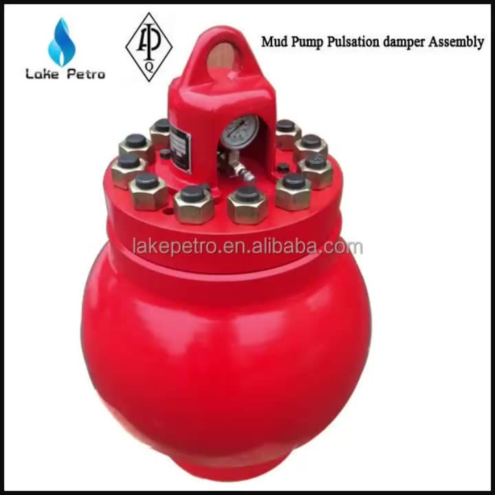
Mud Pump Pulsation Dampener is usually installed on the discharge line to reduce the fluctuation of pressure and displacement of the drilling mud pump.
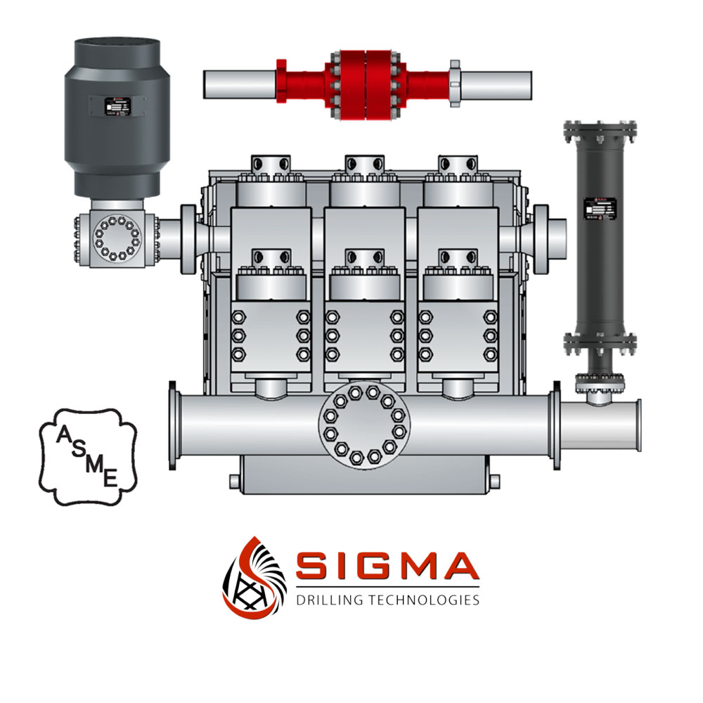
Mud Pump Pulsation Dampener is a pneumatic device built into the outflow line of each UUD pump to dampen the pressure fluctuations resulting from the action of the pump. Although presented as a surge tank, this device is really a device that can be tuned to greatly diminish the output pulsations transmitted downstream from the mud pump. Unfortunately, the effectiveness of the pulsation dampener is a function of both output pump pressure and frequency of the pump pulsations.

All pulsation dampeners utilize one of two methods for mitigating energy produced by reciprocating pumps; compression or exchange. The traditional gas-charged dampeners use a compressible gas cushion, either by a gas over liquid or gas-filled diaphragms, bladders, or cartridge. As the reciprocating pump produces pressure spikes, the gas compresses, thus absorbing the pressure difference and smoothing the pumped media flow. For maintenance free pulsation dampeners, rely on energy exchange. There is a common misconception regarding maintenance free pulsation control devices that the pumped media is compressible enough to absorb the reciprocating pumps’ pressure spikes. This is not true. However, the maintenance free pulsation dampeners work by utilizing the kinetic energy exchange. This kinetic energy exchange can only happen if the pulsation dampener’s volume is large enough to dissipate enough energy to reduce the adverse effects caused by the reciprocating pump. This is why maintenance free pulsation devices require massive volumes to be effective. Sigma Drilling Technologies has developed a pulsation dampening system that utilizes both methods for reducing the harmful effects of positive displacement pumps, both compression and exchange.

This multistage system utilizes several of Sigma’s advanced products that are proven to maximize efficiencies and upgrade operations of any reciprocating pumping system by themselves.
By protectively coating both inside and outside the system’s Charge Free Stabilizer™ and the Charge Free Dampener™, the system is entirely corrosion-resistant. The Charge Free Dampening System™ is easily the most protected pulsation equipment available.
The Charge Free Dampening System™ is categorically the most sophisticated pulsation control available for your rigs’ pumping operations. With the introduction of the CFD System, Sigma Drilling Technologies proves to be the authority on state-of-the-art advancements in pulsation control technologies.
For more information about pulsation dampeners, we sat down with Brandon Dalrymple and Nathan Ackeret fromBlacoh Fluid Control(manufacturer of pulsation dampeners, surge suppressors, and inlet stabilizers), and asked them to answer a few of our customers’ most common questions about pulsation dampeners.
Pulsation dampeners absorb the energy from the pulse wave created by a positive displacement pump, much like a shock absorber on a vehicle. Absorbing those pulse waves protects pipe welds and supports, and system components from damage due to pressure or excess movement.
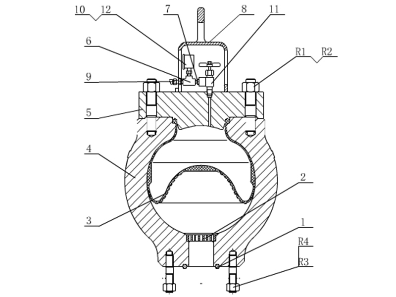
A pulsation dampener creates an area of low pressure in the system with enough volume to absorb the pulsation. The pulsation dampener has a membrane with a "cushion" of compressible gas/air behind it that flexes to absorb the pulse, allowing a laminar flow downstream of the dampener.
Pulsation dampeners are commonly used wherever a positive displacement pump discharges flow in an unsteady manner, and where the pulse is not desired for the piping system. Air operated double diaphragm, metering and hose/peristaltic pumps typically benefit from a pulsation dampener.
The type of pulsation dampener used is typically defined by where they are placed in the system, and what they need to do. For example, "pulsation dampeners" are on the downstream side of the pump, "inlet stabilizers" are on the inlet side of the pump, and an accumulator or "surge suppressor" is used next to a valve or other device that restricts the flow in a system.
This video shows where you would place an inlet stabilizer, and how it is used to reduce the pulsation with an air operated diaphragm pump in suction lift conditions.

Positive displacement pumps effectively pump fluid at a constant average flow rate. However, because the individual pumping elements of these pumps discharge discrete quantities of fluid, the instantaneous flow rate varies in a cyclic fashion.
Pulsations are observed in the system as pressure spikes. In the positive displacement pump family, single-shoe peristaltic pumps generally create the largest pulse, followed by two-shoe peristaltic pumps. Triplex and quintuplex pumps have smooth output curves because of piston overlap. Gear pumps can have extremely small pulses, but pulsations still exist. This pulsating flow can cause operational problems and shorten equipment’s service life.
To alleviate the problem, pulsation dampeners can be added to the pumping system to absorb pressure spikes and smooth fluid flow. Figure 1 shows the undampened pressure spikes from a triplex pump in green. The dampened pressure curve from the same pump with the same system settings are indicated in blue. Six pulses per revolution occur instead of the expected three. This is a result of piston overlap.
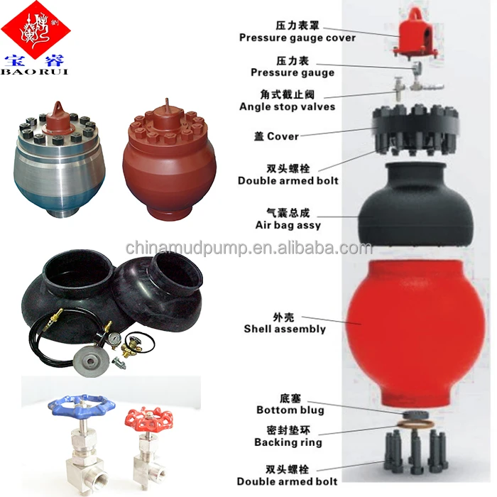
The most common type of pulsation dampener is a hydro-pneumatic pressure vessel containing compressed air or nitrogen and a bladder—or bellows—that separate the process fluid from the gas charge. To maximize the dampening effect, pulsation dampeners should be installed as close as possible to the pump discharge with a gas charge that is slightly below the normal system pressure. More important, pulsation dampeners must be properly sized for the system.
A dampener that is undersized cannot adequately compensate for pressure and flow fluctuations. An oversized dampener will act as an accumulator, storing too much fluid. This will cause slow stabilization and a delayed response to system changes. The first step in sizing a dampener is to quantitatively define the acceptable performance.
Sizing pulsation dampeners is straightforward. However, calculating the system pressure fluctuations is more complex. Fluid discharge rates from pumps are difficult to mathematically model. For example, in Figure 1, the spikes are not even. Theoretically, they should be equal. Mathematical models must be physically tested to verify their accuracy.
Pumps with multiple heads and higher pulse frequencies can make the calculations more difficult. The distance from one output port to the next is generally not constant. This creates a shift in the piston overlap with intermittent larger and smaller pulses. Calculating the magnitude or frequency of noise pulses that can develop or resonate in a system is difficult.
Piping arrangement—such as bends, reducers and valves—combined with the opening and closing of pump discharge check valves can create noise in the fluid called pressure pulses. Because many variables must be considered, each pump type should be tested with and without a dampener. The pressure curve data can be recorded and used to find the pump’s formula constant. This constant can be used in future calculations. As long as other pump models are similar to the test unit, accurately predicting the magnitude of line pressure variation with a given size dampener is possible.
The pressure in a piping system will rise sharply when a volume of fluid is added to the line. It accelerates the mass of the fluid in the piping system. This is acceleration head, and it needs to be minimized with a dampener. The effect and its impact must be considered on both the inlets and outlets of positive displacement pumps. On the inlet side, cavitation and partial filling of pump cavities can damage pump components and make the pump much louder than normal.
System noise must be considered when taking measurements because it can give higher-than-expected results. Noise in the pumping liquid can generally be ignored, but in some situations, system noise needs to be controlled. Noise can cause pressure relief valves to leak, damage sensitive components and create occupational safety hazards. Dampeners typically reduce noise, and some are specifically designed for this purpose.
Several different styles of dampeners are available, and each has advantages and disadvantages. This article focuses on reducing the pressure pulses caused by pulsing flow. The principles and the method for calculating the appropriate size dampener for this application are the same for most dampeners.
A dampener absorbs a fluid pulse and then allows the fluid to flow back into the system between pulses. Most dampeners use a gas charge that is set slightly below the normal system pressure and is compressed by the pulse of fluid. The gas then expands when fluid is released.
In actual practice, either formula would probably work if the pressure fluctuations are small relative to the system pressure. The pump constant that is developed would cover the inaccuracies in the formula as long as the pressure variations are similar. In this article, the isentropic formula is used.
To determine the pump constant, the volume from a single pulse of the pump must first be determined. Then an initial estimate of dampener size is made, and the corresponding value of dampener volume is applied. The amount of gas in the dampener will be less than the total dampener volume, which needs to be factored into the calculation. A typical range of 80 to 90 percent of the dampener volume should be gas if the dampener is properly charged. These give an initial gas volume:
The constant reduces the pulse volume to account for flow leaving the dampener while the pulse is entering. It also accounts for piston overlap, which changes the effective size of the pulse. Adding the factor to the isentropic formula and solving for the pump factor gives us the following equation:
For example, the pressure curve from an undampened, two-shoe, 2.5-inch peristaltic hose pump shows a sharp increase in flow, followed by a “no-flow” or negative flow zone. In this instance, the line has a ball valve that is creating the flow restriction for back pressure. The blue line shows the undampened pressure spikes (see Figure 2). The red line shows the pressure changes of the same pump with the same back pressure valve setting but now using a dampener. This sample dampener has an actual gas volume of 415 cubic inches, and the dampener is 90-percent gas filled. The base pressure is 14.15 psig, and the pulse is 76.9 cubic inches. If the pressure fluctuation is calculated using the isentropic pressure formula, the result is:
It is important to remember to add 14.7 psi to convert from gauge to absolute pressure, then subtract 14.7 psi again to get the final result in gauge pressure. This pump setup was tested, and the actual pressure variation was determined to be 7.38 psi. Therefore, the result is:
If the example above is used and it is decided that a pressure fluctuation of 15 psi would be acceptable, the formula with the previously calculated pump factor can be used to determine what size of dampener is needed.
Table 1 lists some approximate pump constant factors that can be used when sizing dampeners for different pump types. These factors are approximate, and the results may vary significantly with the many variables involved.
A triplex plunger pump doses methanol, which is metered on the discharge side. Without a dampener to control pulsations and smooth out the flow, the installed flow meters were giving inaccurate readings.
When using a triplex pump, all three chambers of the pump must stay full of fluid with no voids. Any voids or pockets can cause seal leakage, pump vibration and excess pump noise.
The solution was to install a pulsation dampener at the pump discharge to smooth the flow and remove pressure pulsations. This allowed the dosing to be more accurate. An inlet stabilizer (suction dampener) was also installed on the inlet side of the pump to act as an accumulator to keep the pump chambers filled. The inlet stabilizer also removed pulsations created by the pump on its inlet stroke. Both devices were sized based on the pump type, flow rate and operating pressure.
During the filling of a drum with a flexible hose, an automatic valve would close and cause a water hammer effect. All the pipes leading into the system would shake until they broke loose from their supports. The solution was to install a pulsation dampener at the beginning of the flexible hose connection.
The pulsation dampener was sized based on the flow parameters and installed at the beginning of the flexible hose. When the automatic valve closed, the hose and pulsation dampener effectively absorbed a portion of the water hammer, eliminating pipe shake and improving operational safety.
The sizing of a pulsation dampener is critical to achieving the desired result. Finding and using the correct constant pump factor in dampener sizing is a key part of the solution. As long as the pulsation dampener is properly sized, positioned and charged, it will effectively dampen pulsations to protect equipment and keep the pressure pulses within design parameters.
This equipment plays an important role as an accessory to Yamada air-operated double diaphragm pumps. The pulsation dampener serves to reduce pulsation produced in operation and to assure stable discharge flow and pressure.
When pulsations occur with pump operation, it will result in the pressure in Chamber Bbeing greater than that in Chamber A. The diaphragm will act as an air cushion and automatically adjust to this pressure change and absorb the pulsations.
This operation will shift the center rod position upwards and allow more air in Chamber Athrough the air inlet, returning the diaphragm to a neutral position. If liquid pressure decreases, air pressure in Chamber Acauses the diaphragm to move downward, shifting shaft location and changing valve position, releasing excess air pressure in Chamber Awhich returns diaphragm to a neutral position. This action causes a reduction in surges and pulsation caused by a air operated double diaphragm pumps
Positive displacement pumps effectively pump fluid at a constant average flow rate. However, because the individual pumping elements of these pumps discharge discrete quantities of fluid, the instantaneous flow rate varies in a cyclic fashion.
Pulsations are observed in the system as pressure spikes. In the positive displacement pump family, single-shoe peristaltic pumps generally create the largest pulse, followed by two-shoe peristaltic pumps. Triplex and quintuplex pumps have smooth output curves because of piston overlap. Gear pumps can have extremely small pulses, but pulsations still exist. This pulsating flow can cause operational problems and shorten equipment’s service life.
To alleviate the problem, pulsation dampeners can be added to the pumping system to absorb pressure spikes and smooth fluid flow. Figure 1 shows the undampened pressure spikes from a triplex pump in green. The dampened pressure curve from the same pump with the same system settings are indicated in blue. Six pulses per revolution occur instead of the expected three. This is a result of piston overlap.
The most common type of pulsation dampener is a hydro-pneumatic pressure vessel containing compressed air or nitrogen and a bladder—or bellows—that separate the process fluid from the gas charge. To maximize the dampening effect, pulsation dampeners should be installed as close as possible to the pump discharge with a gas charge that is slightly below the normal system pressure. More important, pulsation dampeners must be properly sized for the system.
A dampener that is undersized cannot adequately compensate for pressure and flow fluctuations. An oversized dampener will act as an accumulator, storing too much fluid. This will cause slow stabilization and a delayed response to system changes. The first step in sizing a dampener is to quantitatively define the acceptable performance.
Sizing pulsation dampeners is straightforward. However, calculating the system pressure fluctuations is more complex. Fluid discharge rates from pumps are difficult to mathematically model. For example, in Figure 1, the spikes are not even. Theoretically, they should be equal. Mathematical models must be physically tested to verify their accuracy.
Pumps with multiple heads and higher pulse frequencies can make the calculations more difficult. The distance from one output port to the next is generally not constant. This creates a shift in the piston overlap with intermittent larger and smaller pulses. Calculating the magnitude or frequency of noise pulses that can develop or resonate in a system is difficult.
Piping arrangement—such as bends, reducers and valves—combined with the opening and closing of pump discharge check valves can create noise in the fluid called pressure pulses. Because many variables must be considered, each pump type should be tested with and without a dampener. The pressure curve data can be recorded and used to find the pump’s formula constant. This constant can be used in future calculations. As long as other pump models are similar to the test unit, accurately predicting the magnitude of line pressure variation with a given size dampener is possible.
The pressure in a piping system will rise sharply when a volume of fluid is added to the line. It accelerates the mass of the fluid in the piping system. This is acceleration head, and it needs to be minimized with a dampener. The effect and its impact must be considered on both the inlets and outlets of positive displacement pumps. On the inlet side, cavitation and partial filling of pump cavities can damage pump components and make the pump much louder than normal.
System noise must be considered when taking measurements because it can give higher-than-expected results. Noise in the pumping liquid can generally be ignored, but in some situations, system noise needs to be controlled. Noise can cause pressure relief valves to leak, damage sensitive components and create occupational safety hazards. Dampeners typically reduce noise, and some are specifically designed for this purpose.
Several different styles of dampeners are available, and each has advantages and disadvantages. This article focuses on reducing the pressure pulses caused by pulsing flow. The principles and the method for calculating the appropriate size dampener for this application are the same for most dampeners.
A dampener absorbs a fluid pulse and then allows the fluid to flow back into the system between pulses. Most dampeners use a gas charge that is set slightly below the normal system pressure and is compressed by the pulse of fluid. The gas then expands when fluid is released.
In actual practice, either formula would probably work if the pressure fluctuations are small relative to the system pressure. The pump constant that is developed would cover the inaccuracies in the formula as long as the pressure variations are similar. In this article, the isentropic formula is used.
To determine the pump constant, the volume from a single pulse of the pump must first be determined. Then an initial estimate of dampener size is made, and the corresponding value of dampener volume is applied. The amount of gas in the dampener will be less than the total dampener volume, which needs to be factored into the calculation. A typical range of 80 to 90 percent of the dampener volume should be gas if the dampener is properly charged. These give an initial gas volume:
The constant reduces the pulse volume to account for flow leaving the dampener while the pulse is entering. It also accounts for piston overlap, which changes the effective size of the pulse. Adding the factor to the isentropic formula and solving for the pump factor gives us the following equation:
For example, the pressure curve from an undampened, two-shoe, 2.5-inch peristaltic hose pump shows a sharp increase in flow, followed by a “no-flow” or negative flow zone. In this instance, the line has a ball valve that is creating the flow restriction for back pressure. The blue line shows the undampened pressure spikes (see Figure 2). The red line shows the pressure changes of the same pump with the same back pressure valve setting but now using a dampener. This sample dampener has an actual gas volume of 415 cubic inches, and the dampener is 90-percent gas filled. The base pressure is 14.15 psig, and the pulse is 76.9 cubic inches. If the pressure fluctuation is calculated using the isentropic pressure formula, the result is:
It is important to remember to add 14.7 psi to convert from gauge to absolute pressure, then subtract 14.7 psi again to get the final result in gauge pressure. This pump setup was tested, and the actual pressure variation was determined to be 7.38 psi. Therefore, the result is:
If the example above is used and it is decided that a pressure fluctuation of 15 psi would be acceptable, the formula with the previously calculated pump factor can be used to determine what size of dampener is needed.
Table 1 lists some approximate pump constant factors that can be used when sizing dampeners for different pump types. These factors are approximate, and the results may vary significantly with the many variables involved.
A triplex plunger pump doses methanol, which is metered on the discharge side. Without a dampener to control pulsations and smooth out the flow, the installed flow meters were giving inaccurate readings.
When using a triplex pump, all three chambers of the pump must stay full of fluid with no voids. Any voids or pockets can cause seal leakage, pump vibration and excess pump noise.
The solution was to install a pulsation dampener at the pump discharge to smooth the flow and remove pressure pulsations. This allowed the dosing to be more accurate. An inlet stabilizer (suction dampener) was also installed on the inlet side of the pump to act as an accumulator to keep the pump chambers filled. The inlet stabilizer also removed pulsations created by the pump on its inlet stroke. Both devices were sized based on the pump type, flow rate and operating pressure.
During the filling of a drum with a flexible hose, an automatic valve would close and cause a water hammer effect. All the pipes leading into the system would shake until they broke loose from their supports. The solution was to install a pulsation dampener at the beginning of the flexible hose connection.
The pulsation dampener was sized based on the flow parameters and installed at the beginning of the flexible hose. When the automatic valve closed, the hose and pulsation dampener effectively absorbed a portion of the water hammer, eliminating pipe shake and improving operational safety.
The sizing of a pulsation dampener is critical to achieving the desired result. Finding and using the correct constant pump factor in dampener sizing is a key part of the solution. As long as the pulsation dampener is properly sized, positioned and charged, it will effectively dampen pulsations to protect equipment and keep the pressure pulses within design parameters.
A discharge dampener is designed and installed in the pipe to help absorb this pressure spike. The dampener consists of a vessel filled with gas or compressible material. When there are sudden changes in flow, the compressible material is able to compress and expand, similar to jumping onto your bed. The video below demonstrates the effects with and without a dampener.
By installing a pulsation dampener, the intensity of these spikes are reduced to controlled levels.A dampener should be sized and installed in all piping that may experience a harmful level of pressure spikes.
Pulsation dampeners can be purchased in a variety of shapes, sizes, and designs. It is important to size a pulsation dampener for a specific application. Incorrect sizing or incompatible materials may cause a danger to equipment, systems, and personnel.
Membrane Pulsation Dampener: A membrane-type dampener provides a solid separation between the pumping fluid and the compressible gas. The membrane resides within the dampener and allows for the pressure to be transferred to the gas, without any mixing of the gas into the fluid.
Bladder Pulsation Dampener: A bladder type dampener fully encloses the compressible gas within a bladder. This setup ensures there is no leakage of the gas into the pumping fluid. The pressure pulsations are transferred to the gas as the bladder expands and contracts.
Bellows Pulsation Dampener: A bellows-type dampener works the same way as a bladder type dampener. However, by using a bellows-type design, it can be made with other types of materials such as PTFE or Stainless Steel. This type of dampening system is used when pumping corrosive materials that may deteriorate more common materials.
Pressure Vessel Style: A pressure vessel dampener, sometimes referred to as a “zero maintenance” style dampener does not use any moving parts. They are only effective at very high pressures. Fluids, including water, do have some degree of compressibility. Pressure Vessel Style dampeners allow for the pressure of the fluid to be dissipated within the vessel by the small amount of compressibility within the pumping fluid. In very high-pressure applications, a pressure vessel style dampener may be the only type of dampener available. It is important to note that this style of dampener does not operate as effectively as other types of dampeners.
Flexible piping: Although it is not recommended, flexible piping or hose can act as a pulsation dampener in emergency situations. As the fluid flow changes, the flexible piping is able to “move” and allow a dampening effect on the fluid. Flexible piping still requires proper sizing to reduce pressure spikes. Improper usage may result in damage to equipment and endangerment of equipment operators.
Equipment that rapidly changes flow rates is recommended to have a pulsation dampener. Plunger pumps, for example, have a highly variable flow rate. The average flow rate of a plunger pump can be accurately predicted. However, each rotation of the crankshaft produces several changes in flow velocities.
When a plunger pump is running slowly, these pressure spikes can be ignored. In most cases, they will not produce enough of a spike to create damage. When the pump is running at full speed, this full cycle is taking place many times per second. The pressure spikes caused by these sudden changes will likely need a pulsation dampener.
The image above shows the visible pulsations created by a reciprocating quintuplex pump. Using flexible hoses on the inlet and outlet, the pressure fluctuations through the hose can easily be seen. Since steel piping is more rigid, it may be more difficult to visually see pressure vibrations before damage to piping and the surrounding systems takes place. It is important to correctly determine if a dampener is needed and to correctly install the required size before operating the pump system.
It is important to note that pressure pulsations are not a function of pressure. The operational pressures of a system have very little effect on the resulting pressure pulsations. Both suction and discharge sides of a reciprocating pump are susceptible to pulsations and resulting damage. Both the suction and discharge dampeners operate independently of each other. Proper sizing and installation of both suction and discharge dampeners are required for proper protection of pumping equipment and systems.


 8613371530291