
mud pump design calculation in stock

Rig pump output, normally in volume per stroke, of mud pumps on the rig is one of important figures that we really need to know because we will use pump out put figures to calculate many parameters such as bottom up strokes, wash out depth, tracking drilling fluid, etc. In this post, you will learn how to calculate pump out put for triplex pump and duplex pump in bothOilfield and Metric Unit.

The purpose of this article is to present some guidelines and simplified techniques to size pumps and piping typically used in mud systems. If unusual circumstances exist such as unusually long or complicated pipe runs or if very heavy or viscous drilling muds are used, a qualified engineer should analyze the system in detail and calculate an exact solution.
To write about pumps, one must use words that are known and well understood. For example, the label on the lefthand side of any centrifugal pump curve is Total Head Feet. What does this mean?
Total Head remains constant for a particular pump operated at a constant speed regardless of the fluid being pumped. However, a pump’s pressure will increase as the fluid density (mud weight) increases according to the following relationship:
Note that the pump pressure almost doubled. It follows that the required pump horsepower has increased by the same percentage. If the pump required 50 HP for water service, it will require the following horsepower for 16 lb/gal mud:
To summarize, a pump’s Total Head remains constant for any fluid pumped, only the pump pressure and pump horsepower will change. Therefore, a pump motor must be sized according to the heaviest weight mud to be pumped.
In our example problem, the required desilter pressure head is 75 ft. for any mud weight. However, the pressure would be 30.3 PSIG for water or 43.6 PSIG for 12 lb mud or 58.1 PSIG for 16 lb mud. A good rule of thumb is that the required pressure (PSIG) equals 4 times the mud weight (12 LB/GAL x 4 = 48 PSIG).
Determine the required pressure head and flow rate. If the pump is to supply a device such as a mud mixing hopper or a desilter, consult the manufacturer’s information or sales representative to determine the optimum flow rate and pressure head required at the device. (On devices like desilters the pressure head losses downstream of the device are considered negligible and are usually disregarded.)
Select the basic pump to pump the desired flow rate. Its best to refer to a manufacturer’s pump curve for your particular pump. (See example – Figure 3).
The pump’s impeller may be machined to a smaller diameter to reduce its pressure for a given application. Refer to the manufacturer’s pump curves or manufacturer’s representative to determine the proper impeller diameter. Excessive pressure and flow should be avoided for the following reasons:
The pump must produce more than 75 FT-HD at the pump if 75 FT-HD is to be available at the desilter inlet and the pump’s capacity must be at least 800 GPM. Therefore, we should consider using one of the following pumps from the above list: 4″ x 5″ Pump 1750 RPM – 1000 GPM at 160 FT-HD; or 5″ x 6″ Pump 1750 RPM – 1200 GPM at 160 FT-HD.
The pump suction and discharge piping is generally the same diameter as the pump flange diameters. The resulting fluid velocities will then be within the recommended ranges of 4 to 10 FT/SEC for suction lines and 4 to 12 FT/
SEC for discharge lines. Circumstances may dictate that other pipe diameters be used, but remember to try to stay within the above velocity guidelines. Smaller pump discharge piping will create larger pressure drops in the piping
and the pump may not be able to pump the required amount of fluid. (For example, don’t use a 4″ discharge pipe on a 6″ x 8″ pump and expect the pump’s full fluid flow.)
6″ pipe may be used for the suction pipe since it is relatively short and straight and the pump suction is always flooded. 6″ pipe is fully acceptable for the discharge pipe and is a good choice since the desired header is probably 6″ pipe.
8″ pipe may be used for the suction pipe (V = 5.13 FT/SEC) since V is still greater than 4 FT/SEC. 8″ pipe would be preferred if the suction is long or the suction pit fluid level is low with respect to the pump.

For contour impeller applications, values must be significantly faster (i.e., smaller numbers) to achieve the same results, but because of the impeller design, air entrainment is less probable. In symmetrical compartments, the fluid has a nearly equal distance to travel from the center of the impeller shaft or from the impeller blade tip before it contacts the vessel wall. Agitators should be placed where the shaft is centered in the tank or compartment.
For round tanks with dish or cone bottoms, calculations for working fluid volume are based on straight wall height (i.e., this height is measured from the tank top to where the tank joins the cone or dish at the bottom). This leaves adequate free space above the maximum fluid operating level. In all cases, if H<5 feet (1.5 m), a radial flow impeller should be specified.

When choosing a size and type of mud pump for your drilling project, there are several factors to consider. These would include not only cost and size of pump that best fits your drilling rig, but also the diameter, depth and hole conditions you are drilling through. I know that this sounds like a lot to consider, but if you are set up the right way before the job starts, you will thank me later.
Recommended practice is to maintain a minimum of 100 to 150 feet per minute of uphole velocity for drill cuttings. Larger diameter wells for irrigation, agriculture or municipalities may violate this rule, because it may not be economically feasible to pump this much mud for the job. Uphole velocity is determined by the flow rate of the mud system, diameter of the borehole and the diameter of the drill pipe. There are many tools, including handbooks, rule of thumb, slide rule calculators and now apps on your handheld device, to calculate velocity. It is always good to remember the time it takes to get the cuttings off the bottom of the well. If you are drilling at 200 feet, then a 100-foot-per-minute velocity means that it would take two minutes to get the cuttings out of the hole. This is always a good reminder of what you are drilling through and how long ago it was that you drilled it. Ground conditions and rock formations are ever changing as you go deeper. Wouldn’t it be nice if they all remained the same?
Centrifugal-style mud pumps are very popular in our industry due to their size and weight, as well as flow rate capacity for an affordable price. There are many models and brands out there, and most of them are very good value. How does a centrifugal mud pump work? The rotation of the impeller accelerates the fluid into the volute or diffuser chamber. The added energy from the acceleration increases the velocity and pressure of the fluid. These pumps are known to be very inefficient. This means that it takes more energy to increase the flow and pressure of the fluid when compared to a piston-style pump. However, you have a significant advantage in flow rates from a centrifugal pump versus a piston pump. If you are drilling deeper wells with heavier cuttings, you will be forced at some point to use a piston-style mud pump. They have much higher efficiencies in transferring the input energy into flow and pressure, therefore resulting in much higher pressure capabilities.
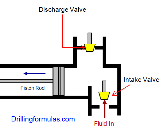
Piston-style mud pumps utilize a piston or plunger that travels back and forth in a chamber known as a cylinder. These pumps are also called “positive displacement” pumps because they literally push the fluid forward. This fluid builds up pressure and forces a spring-loaded valve to open and allow the fluid to escape into the discharge piping of the pump and then down the borehole. Since the expansion process is much smaller (almost insignificant) compared to a centrifugal pump, there is much lower energy loss. Plunger-style pumps can develop upwards of 15,000 psi for well treatments and hydraulic fracturing. Centrifugal pumps, in comparison, usually operate below 300 psi. If you are comparing most drilling pumps, centrifugal pumps operate from 60 to 125 psi and piston pumps operate around 150 to 300 psi. There are many exceptions and special applications for drilling, but these numbers should cover 80 percent of all equipment operating out there.
The restriction of putting a piston-style mud pump onto drilling rigs has always been the physical size and weight to provide adequate flow and pressure to your drilling fluid. Because of this, the industry needed a new solution to this age-old issue.
As the senior design engineer for Ingersoll-Rand’s Deephole Drilling Business Unit, I had the distinct pleasure of working with him and incorporating his Centerline Mud Pump into our drilling rig platforms.
In the late ’90s — and perhaps even earlier — Ingersoll-Rand had tried several times to develop a hydraulic-driven mud pump that would last an acceptable life- and duty-cycle for a well drilling contractor. With all of our resources and design wisdom, we were unable to solve this problem. Not only did Miller provide a solution, thus saving the size and weight of a typical gear-driven mud pump, he also provided a new offering — a mono-cylinder mud pump. This double-acting piston pump provided as much mud flow and pressure as a standard 5 X 6 duplex pump with incredible size and weight savings.
The true innovation was providing the well driller a solution for their mud pump requirements that was the right size and weight to integrate into both existing and new drilling rigs. Regardless of drill rig manufacturer and hydraulic system design, Centerline has provided a mud pump integration on hundreds of customer’s drilling rigs. Both mono-cylinder and duplex-cylinder pumps can fit nicely on the deck, across the frame or even be configured for under-deck mounting. This would not be possible with conventional mud pump designs.
Centerline stuck with their original design through all of the typical trials and tribulations that come with a new product integration. Over the course of the first several years, Miller found out that even the best of the highest quality hydraulic cylinders, valves and seals were not truly what they were represented to be. He then set off on an endeavor to bring everything in-house and began manufacturing all of his own components, including hydraulic valves. This gave him complete control over the quality of components that go into the finished product.
The second generation design for the Centerline Mud Pump is expected later this year, and I believe it will be a true game changer for this industry. It also will open up the application to many other industries that require a heavier-duty cycle for a piston pump application.

Oil and Gas drilling process - Pupm output for Triplex and Duplex pumpsTriplex Pump Formula 1 PO, bbl/stk = 0.000243 x ( in) E.xample: Determine the pump output, bbl/stk, at 100% efficiency for a 7" by 12". triplex pump: PO @ 100%,= 0.000243 x 7 x12 PO @ 100% = 0.142884bbl/stk Adjust the pump output for 95% efficiency: Decimal equivalent = 95 + 100 = 0.95 PO @ 95% = 0.142884bbl/stk x 0.95 PO @ 95% = 0.13574bbl/stk Formula 2 PO, gpm = [3(D x 0.7854)S]0.00411 x SPM where D = liner diameter, in. S = stroke length, in. SPM = strokes per minute Determine the pump output, gpm, for a 7" by 12". triplex pump at 80 strokes per minute: PO, gpm = [3(7 x 0.7854) 1210.00411 x 80 PO, gpm = 1385.4456 x 0.00411 x 80 PO = 455.5 gpm
Example:Duplex Pump Formula 1 0.000324 x (liner diameter, in) x ( stroke lengh, in) = ________ bbl/stk -0.000162 x (rod diameter, in) x ( stroke lengh, in) = ________ bbl/stk Pump out put @ 100% eff = ________bbl/stk Example: Determine the output, bbl/stk, of a 5 1/2" by 14" duplex pump at 100% efficiency. Rod diameter = 2.0": 0.000324 x 5.5 x 14 = 0.137214bbl/stk -0.000162 x 2.0 x 14 = 0.009072bbl/stk Pump output @ 100% eff. = 0.128142bbl/stk Adjust pump output for 85% efficiency: Decimal equivalent = 85 100 = 0.85 PO@85%)= 0.128142bbl/stk x 0.85 PO@ 85% = 0.10892bbl/stk Formula 2
PO. bbl/stk = 0.000162 x S[2(D) - d] where S = stroke length, in. D = liner diameter, in. d = rod diameter, in. Example: Determine the output, bbl/stk, of a 5 1/2". by 14". duplex pump @ 100% efficiency. Rod diameter = 2.0in.: PO@100%=0.000162 x 14 x [ 2 (5.5) - 2 ] PO @ 100%)= 0.000162 x 14 x 56.5 PO@ 100%)= 0.128142bbl/stk Adjust pump output for 85% efficiency: PO@85%,= 0.128142bb/stkx 0.85 PO@8.5%= 0.10892bbl/stk Metric calculation Pump output, liter/min = pump output. liter/stk x pump speed, spm. S.I. units calculation Pump output, m/min = pump output, liter/stk x pump speed, spm. Mud Pumps Mud pumps drive the mud around the drilling system. Depending on liner size availability they can be set up to provide high pressure and low flow rate, or low pressure and high flow rate. Analysis of the application and running the Drill Bits hydraulics program will indicate which liners to recommend. Finding the specification of the mud pumps allows flow rate to be calculated from pump stroke rate, SPM. Information requiredo Pump manufacturer o Number of pumps o Liner size and gallons per revolution Weight As a drill bit cutting structure wears more weight will be required to achieve the same RoP in a homogenous formation. PDC wear flats, worn inserts and worn milled tooth teeth will make the bit drill less efficiently. Increase weight in increments of 2,000lbs approx. In general, weight should be applied before excessive rotary speed so that the cutting structure maintains a significant depth of cut to stabilise the bit and prevent whirl. If downhole weight measurements are available they can be used in combination with surface measurements to gain a more accurate representation of what is happening in the well bore.

Pumps tend to be one of the biggest energy consumers in industrial operations. Pump motors, specifically, require a lot of energy. For instance, a 2500 HP triplex pump used for frac jobs can consume almost 2000 kW of power, meaning a full day of fracking can cost several thousand dollars in energy costs alone!
So, naturally, operators should want to maximize energy efficiency to get the most for their money. Even a 1% improvement in efficiency can decrease annual pumping costs by tens of thousands of dollars. The payoff is worth the effort. And if you want to remotely control your pumps, you want to keep efficiency in mind.
In this post, we’ll point you in the right direction and discuss all things related to pump efficiency. We’ll conclude with several tips for how you can maintain pumping efficiency and keep your energy costs down as much as possible.
In simple terms, pump efficiency refers to the ratio of power out to power in. It’s the mechanical power input at the pump shaft, measured in horsepower (HP), compared to the hydraulic power of the liquid output, also measured in HP. For instance, if a pump requires 1000 HP to operate and produces 800 HP of hydraulic power, it would have an efficiency of 80%.
Remember: pumps have to be driven by something, i.e., an electric or diesel motor. True pump system efficiency needs to factor in the efficiency of both the motor AND the pump.
Consequently, we need to think about how electrical power (when using electric motors) or heat power (when using combustion engines) converts into liquid power to really understand pump efficiency.
Good pump efficiency depends, of course, on pump type and size. High-quality pumps that are well-maintained can achieve efficiencies of 90% or higher, while smaller pumps tend to be less efficient. In general, if you take good care of your pumps, you should be able to achieve 70-90% pump efficiency.
Now that we have a better understanding of the pump efficiency metric, let’s talk about how to calculate it. The mechanical power of the pump, or the input power, is a property of the pump itself and will be documented during the pump setup. The output power, or hydraulic power, is calculated as the liquid flow rate multiplied by the "total head" of the system.
IMPORTANT: to calculate true head, you also need to factor in the work the pump does to move fluid from the source. For example, if the source water is below the pump, you need to account for the extra work the pump puts in to draw source water upwards.
*Note - this calculation assumes the pump inlet is not pressurized and that friction losses are minimal. If the pump experiences a non-zero suction pressure, or if there is significant friction caused by the distance or material of the pipe, these should be factored in as well.
You"ll notice that the elevation head is minimal compared to the discharge pressure, and has minimal effect on the efficiency of the pump. As the elevation change increases or the discharge pressure decreases, however, elevation change will have a greater impact on total head.
Obviously, that’s a fair amount of math to get at the pump efficiency, considering all of the units conversions that need to be done. To avoid doing these calculations manually, feel free to use our simple pump efficiency calculator.
Our calculations use static variables (pump-rated horsepower and water source elevation) and dynamic variables (discharge flow and pressure). To determine pump efficiency, we need to measure the static variables only once, unless they change.
If you want to measure the true efficiency of your pump, taking energy consumption into account, you could add an electrical meter. Your meter should consist of a current transducer and voltage monitor (if using DC) for electrical motors or a fuel gauge for combustion. This would give you a true understanding of how pump efficiency affects energy consumption, and ultimately your bank account.
Up until this point, we’ve covered the ins and outs of how to determine pump efficiency. We’re now ready for the exciting stuff - how to improve pump efficiency!
One of the easiest ways to improve pump efficiency is to actually monitor pumps for signs of efficiency loss! If you monitor flow rate and discharge (output power) along with motor current or fuel consumption, you’ll notice efficiency losses as soon as they occur. Simply having pump efficiency information on hand empowers you to take action.
Another way to increase efficiency is to keep pumps well-maintained. Efficiency losses mostly come from mechanical defects in pumps, e.g., friction, leakages, and component failures. You can mitigate these issues through regular maintenance that keeps parts in working order and reveals impending failures. Of course, if you are continuously monitoring your pumps for efficiency drops, you’ll know exactly when maintenance is due.
You can also improve pump efficiency by keeping pumps lubricated at all times. Lubrication is the enemy of friction, which is the enemy of efficiency (“the enemy of my enemy is my friend…”).
A fourth way to enhance pump efficiency is to ensure your pumps and piping are sized properly for your infrastructure. Although we’re bringing this up last, it’s really the first step in any pumping operation. If your pumps and piping don’t match, no amount of lubricant or maintenance will help.
In this post, we’ve given you the full rundown when it comes to calculating and improving pump efficiency. You can now calculate, measure, and improve pump efficiency, potentially saving your business thousands of dollars annually on energy costs.
For those just getting started with pump optimization, we offer purpose-built, prepackaged solutions that will have you monitoring pump efficiency in minutes, even in hazardous environments.
REASON: This is the mud engineers Bible on the rig. It is based on prior knowledge of all drilling parameters and gives you a step by step plan for present well being drilled. It would guide you all though the drilling process.
Study your silos, pits, mud tanks, storage tank names, its contents, volume, dead volume capacity, properties of their contents (mud: especially Mud weight).
REASON: You don’t want to be taken unawares, you need to know the type of mud you have in each pit (where your backup mud is, kill mud if any, premix, etc.), you need to be sure you have enough mud to reach TD (Total depth) most especially if the logistics of transporting mud to the rig n’est pas facile, or takes days to arrive. Finally without knowing the properties of the mud you are introducing to the active system you would not be sure if what is affecting your active mud system is coming from the formation or from the mud you are introducing to the active mud.
REASON: You need to be sure the shaker screens can handle the flow if the mud is cold if not temporarily screen down to a lower size mesh or ask the driller to reduce the flow rate if permissible.
REASON: Drilling fluids would normally splash the rig crew on the rig floor while pulling and racking back pipes when a stand is removed from the drill string. So a slug (same mud but with 2-2.5 ppg higher density) would be prepared in the slug tank, and pumped into the drill string. This keeps the fluids level inside the drill pipe below the surface when tripping drill pipe.
For a leak off test (LOT), the mud has to be circulated to obtain uniform weight and condition. The primary concern for the mud engineer is to ensure an equal mud weight all through the mud. Mud weight going in to the hole should be equal to mud weight coming out of the hole at the shakers.
REASON: The well needs to be properly monitored. Instead speak with the mud loggers to convert the pit you want to transfer fluid from to the active system from a Reserve pit to an Active pit on their system then you can gradually make your transfers that way all volumes would be shown as active pit volume.
REASON: If the amount and average specific gravity of the solids in both fluids (i.e. the density) are different the mud weight would be a good indicator of the fluids interface during a displacement.
REASON: Calculate your hole volume, that means equal amount of mud on surface will leave you pit, so get the derrick man or personnel assisting you in the pit room to inform you when hole volume has been pumped.
REASON: Using a technique called nephelometry the turbidity can be measured. When light hits a particle the energy is scattered in all directions, it measures the level of light scattered by particles at right angles to the incident light beam. Initial NTU readings of both fluids would be the reference point for identification. After the Hi-vis passes through the driller should be told to stop pumping when the initial NTU of the filtered brine has been achieved.
For water based mud with a low alkalinity use phenolphthalein also. Add it to the mud and check for change of color to pink to know when traces of cement are on surface.
REASON: Note differences in weight between mud, spacer and cement before displacement of cement. The mud weight difference between the three fluids is a good indicator of the fluids interface on surface.
REASON: The first step is removal of cuttings from the borehole and the drilling fluid after which the mud should be condition before placing cement in the wellbore, either the density (not compromising well control) or the rheology depending on the situation. For the rheology, the yield stress, gel strength and plastic viscosity would be reduced hence reducing the driving forces necessary to displace mud with increased mud flexibility while being careful to prevent barite settling.
REASON: With no pit space to store the equivalent mud volume being replaced down hole, all pit levels should be recorded at all stages during the cement job. You would need to visit the pit room and return to the cement unit (while measuring cement density) at appropriate moments.
Measure all tank volumes before cement job i.e. when the mud has been thinned down and pump has been stopped (pit static). In case of leaks or valve mistakes all pits should be recorded.
If we get full returns during cementing it means that the cement displaced equal amount of mud and there was no loss down hole due to the cement job or due to displacement.
Prior to running casing, calculate the displacement of the casing first to know the volume it would displace, calculating from the mud line up to the casing depth.
REASON: From the cement program calculate the total volume of the fluids /cement that would be pumped into the hole that is not mud so as to confirm tank space to receive equal volume from the hole. If no available tank space/storage space then OBM should be back-loaded before the cement job to create space.
REASON: If it’s the pay zone, losses would require the use of acid-soluble LCM to prevent formation damage. Also considering down hole tools and motors, certain concentrations of LCM pills would not be pumped to avoid plugging/damaging the tools unless a bypass tool is part of the BHA.
Bit balling occurs in soft gumbo / swelling shales while drilling, the shale adsorbs water from the mud it then becomes plastic with a ball of compacted shale building up and covering the whole bit, stabilizers and drill collars, thus preventing further drilling progress.
To be certain it’s a bit balling issue we are dealing with the mud engineer should observe some of the following or collect the following information from the following rig personnel, with the first 3 information from the driller being very important:
Selecting a bit with a center jet “C”. Center jets are designed to help prevent bit balling by cleaning the cutters in larger diameter bits drilling soft formations.4
To prevent bit balling from occurring it is advisable to adopt procedures that worked in your geographical area in overcoming bit balling by always reviewing previous drilling mud report (DMR).
· Use mud system that can inhibit clay swelling example: Formulating KCl mud with PHPA (to avoid using higher concentrations of KCl) in which KCl prevents clay swelling while PHPA (partially hydrolyzed polyacrylamide ) coats the shales surfaces (encapsulates) thereby inhibiting their dispersion and incorporation into the mud.7
· “When drilling gumbo, the pH should be maintained at 9.0-10.0. If bit balling occurs, increase the mud alkalinity (PM) to 5 or more with lime”.8
· “If all else fails, before you trip out of the hole, you might pump a walnut-hull sweep. It will tend to sandblast the bit and remove the ball, and won’t hurt the mud. Don’t try this if you are running small jets in the bit, as plugging can be an issue.”11
A Drilling fluids Engineer should be able to observe or carry out a test and subsequently identify the reason for a high or a low mud weight in a water-base mud or an oil-base mud system.
Before looking at the reason why the mud weight reduced or increased from the given mud program specification, it’s good to know that the major function of drilling fluids is to provide sufficient pressure to check influx of gas, oil, and water into the well bore from the drilled formation.
The hydrostatic head of the mud column must be at least equal to that of the formation pressure, and hopefully greater, but not so high as to cause loss of circulation (except where an over balanced / under balanced drilling are specifically desired).
The mud weight materials could be barite, calcium carbonate or soluble salts such as sodium chloride (NaCl), potassium chloride (KCl) and calcium chloride (CaCl2). Sometimes the desired mud weight can be achieved by combining additions of salts and barite.
a. Mud Weight (Density) Test: The mud balance may indicate that mud weight is too high or too low. b. Retort Test: The test may indicate that the percent solids by volume is high, and your solids content calculations (lb/bbl low and high gravity solids) may indicate that barite content is too high or too low. c. Rheology tests: Indicates increase or decrease in viscosity
a. Increase in pump pressure: This can indicate an increase in Mud weight. b. Change in penetration rate: Increase in penetration rate may indicate decrease in mud weight while decrease in penetration rate may indicate increase in mud weight. c. Gas bubbles: This definitely indicates decrease in mud weight.

What type of drill bit are we using (roller cone with teeth or buttons, drag bit, PDC)? What are we using for a mud pump (centrifugal or piston)? How much flow (gallons per minute) and pressure (pounds per square inch) do we have available?
Hydraulics describes how fluid flow inside tubulars and annular spaces uses pressure. Mechanical force (pressure) is supplied by the mud pump—a push or pull which tends a system to change its state of rest or motion.
The relationship of physical properties of a drilling fluid in conjunction with a shear stress (pumping pressure) and a shear rate (velocity of the fluid or flow rate) is termed rheological behavior. Bits, pumps, flow rate and pump pressure, and drilling fluid rheological properties all relate to fluid hydraulics.
Drilling fluid design can minimize this effect. Full control needs optimization of drilling fluid hydraulics. As was noted, hydraulics uses pressure and volume produced by the mud pump. If we can focus the pressure and flow against the cutting structure of the bit, we can keep the cutting surfaces clean; in effect, we will be blasting these surfaces clean with high-pressure fluid flow.
The pressure in our system comes from the mud pump. We know that the pressure of the fluid at the pump is greater than the pressure of the fluid as the fluid exits the borehole.
So, if the pressure gauge at the pump is reading 500 psi and the pressure is effectively zero as the fluid exits the borehole, where did the pressure go? In its simplest form, the available pressure is lost due to overcoming the internal friction of the moving fluid, the friction of passing through the drill string and drill bit, and moving against the borehole walls.
Internally overcoming friction is really overcoming the resistance to flowing, which we have previously defined as viscosity. The total solids content of the drilling fluid (measured as density) and how these solids interact with each other (measured as plastic viscosity and yield point) are used in pressure loss calculations.
Inside our tubulars, turbulent flow can be expected due to pumping volume and rather small internal diameter. Luckily, drill steel will not be eroded by this turbulent flow.
The annulus is a much different environment. We do not want erosion of the borehole walls and we have added drilled cuttings to the drilling fluid that need to be transported to the surface. The magnitude of annular pressure loss is a function of type of flow, annular velocity, and mud properties, requiring laminar flow to maintain borehole wall integrity and effective cuttings transport. An uphole annular velocity of 60 to 120 feet per minute usually meets our requirements.
Rheology and hydraulics calculations provide the means for adjusting the drilling fluid’s properties, the flow rate, and bit nozzle size to optimize system pressure losses under the constraints imposed by the rig equipment.
Exploring this statement may answer some questions about pump type and bit design. The previous discussion would be primarily suited to positive displacement or piston pumps and drill bits that allow for adjusting the bit nozzle size.
Many of you drill with centrifugal pumps and use drill bits with no nozzles or open centers. Sure, you can drill with centrifugal pumps. They do allow for high flow rates, but they also lose efficiency with higher viscosity drilling fluids, have limited pressure limits, and lose efficiency with depth.
Centrifugal pumps do not work as well as positive displacement pumps when using jetted bits. Often the jets are too restrictive and too much pressure is lost at this point, so open center bits are preferred. Hole cleaning and cutting surface cleaning are accomplished by drilling fluid chemistry and flow volume. Hydraulics optimization is seldom used when drilling with centrifugal pumps.
Drag bits are very common in the water well business. Most of the designs have an open center and use flow volume to clean the cutting surface and move the drilled cuttings to the surface. I personally have never seen one with jets unless you consider a PDC bit a sophisticated drag bit.
You can create a “cutting” so large that it can’t be suspended or transported by the drilling fluid. It may be too large to even get past the side of the bit or fit in the annular space around drill collars or stabilizers. This causes packing off and restricts flow. Sometimes these sausages can’t be pumped out of the hole and must be pulled out by tripping out of the hole. In general, drag bits are not good candidates for hydraulics optimization.
The major goal of hydraulics optimization is to balance hole cleaning, pump pressure, and pressure drop across the bit. The drilling fluid’s density and rheological properties are the parameters that affect this hydraulic efficiency.
We looked at each part of the system, using the system approach to troubleshooting. We knew the geology was clay and a shale rock that easily got water wet and sticky. Mud system checked out for this geology. Piston pump for pressure and flow, poor flow coming out of the hole. Long-tooth bit should handle the formations. What’s missing?
We tripped the bit out of the hole and found it all balled up and mud and cuttings packed off around the stabilizer. It was obvious we were not cleaning the cuttings away from the bit teeth and insufficient flow to move them up into the flow stream and to the surface.
We didn’t use any math today at all. Know the geology. Formulate the proper drilling fluid and choose the best bit and pump with as much fluid pressure as you can. Put it to work for you.

For over 50 years, TB Wood’s has led the coupling industry with the original TB Wood’s Sure-Flex design. And we haven’t stopped innovating: this industry favorite just got even better.

Parker’s design expertise in piston sealing applications has resulted in piston cups that outlast the competition by 50%, reducing costly downtime and eliminating leaks

The mud pump piston is a key part for providing mud circulation, but its sealing performance often fails under complex working conditions, which shorten its service life. Inspired by the ring segment structure of earthworms, the bionic striped structure on surfaces of the mud pump piston (BW-160) was designed and machined, and the sealing performances of the bionic striped piston and the standard piston were tested on a sealing performance testing bench. It was found the bionic striped structure efficiently enhanced the sealing performance of the mud pump piston, while the stripe depth and the angle between the stripes and lateral of the piston both significantly affected the sealing performance. The structure with a stripe depth of 2 mm and angle of 90° showed the best sealing performance, which was 90.79% higher than the standard piston. The sealing mechanism showed the striped structure increased the breadth and area of contact sealing between the piston and the cylinder liner. Meanwhile, the striped structure significantly intercepted the early leaked liquid and led to the refluxing rotation of the leaked liquid at the striped structure, reducing the leakage rate.
Mud pumps are key facilities to compress low-pressure mud into high-pressure mud and are widely used in industrial manufacture, geological exploration, and energy power owing to their generality [1–4]. Mud pumps are the most important power machinery of the hydraulic pond-digging set during reclamation [5] and are major facilities to transport dense mud during river dredging [6]. During oil drilling, mud pumps are the core of the drilling liquid circulation system and the drilling facilities, as they transport the drilling wash fluids (e.g., mud and water) downhole to wash the drills and discharge the drilling liquids [7–9]. The key part of a mud pump that ensures mud circulation is the piston [10, 11]. However, the sealing of the piston will fail very easily under complex and harsh working conditions, and consequently, the abrasive mud easily enters the kinematic pair of the cylinder liner, abrading the piston surfaces and reducing its service life and drilling efficiency. Thus, it is necessary to improve the contact sealing performance of the mud pump piston.
As reported, nonsmooth surface structures can improve the mechanical sealing performance, while structures with radial labyrinth-like or honeycomb-like surfaces can effectively enhance the performance of gap sealing [12–14]. The use of nonsmooth structures into the cylinder liner friction pair of the engine piston can effectively prolong the service life and improve work efficiency of the cylinder liner [15–17]. The application of nonsmooth grooved structures into the plunger can improve the performance of the sealing parts [18, 19]. The nonsmooth structures and sizes considerably affect the sealing performance [20]. Machining a groove-shaped multilevel structure on the magnetic pole would intercept the magnetic fluid step-by-step and slow down the passing velocity, thus generating the sealing effect [21–23]. Sealed structures with two levels or above have also been confirmed to protect the sealing parts from hard damage [24]. The sealing performance of the high-pressure centrifugal pump can be improved by adding groove structures onto the joint mouth circumference [25]. The convex, pitted, and grooved structures of dung beetles, lizards, and shells are responsible for the high wear-resistance, resistance reduction, and sealing performance [26–28]. Earthworms are endowed by wavy nonsmooth surface structures with high resistance reduction and wear-resistance ability [29]. The movement of earthworms in the living environment is very similar to the working mode of the mud pump piston. The groove-shaped bionic piston was designed, and the effects of groove breadth and groove spacing on the endurance and wear-resistance of the piston were investigated [30]. Thus, in this study, based on the nonsmooth surface of earthworms, we designed and processed a nonsmooth striped structure on the surface of the mud pump piston and tested the sealing performance and mechanism. This study offers a novel method for prolonging the service life of the mud pump piston from the perspective of piston sealing performance.
The BW-160 mud pump with long-range flow and pressure, small volume, low weight, and long-service life was used here. The dimensions and parameters of its piston are shown in Figure 1.
A striped structure was designed and processed on the contact surface between the piston cup and the cylinder liner. The striped structure was 5 mm away from the outermost part of the lip, which ensured the lip could contact effectively with the cylinder liner. Based on the structural dimensions of the piston cup, we designed a 2-stripe structure, and the very little stripe space affected the service life of the piston [30]. Thus, the stripe space of our bionic piston was set at 5 mm. According to the machining technology, two parameters of stripe depth h and the angle between the stripes and lateral of the piston α were selected (Figure 2).
A mud pump piston sealing performance test bench was designed and built (Figure 3). This bench mainly consisted of a compaction part and a dynamic detection part. The compaction part was mainly functioned to exert pressure, which was recorded by a pressure gauge, to the piston sealed cavity. This part was designed based on a vertical compaction method: after the tested piston and the sealing liquid were installed, the compaction piston was pushed to the cavity by revolving the handle. Moreover, the dynamic detection part monitored the real-time sealing situation and was designed based on the pressure difference method for quantifying the sealing performance. This part was compacted in advance to the initial pressure P0 (0.1 MPa). After compaction, the driving motor was opened, and the tested piston was pushed to drive the testing mud to reciprocate slowly. After 1 hour of running, the pressure P on the gauge was read, and the pressure difference was calculated as , which was used to measure the sealing performance of the piston.
To more actually simulate the working conditions of the mud pump, we prepared a mud mixture of water, bentonite (in accordance with API Spec 13A: viscometer dial reading at 600 r/min ≥ 30, yield point/plastic viscosity radio ≤ 3, filtrate volume ≤ 15.0 ml, and residue of diameter greater than 75 μm (mass fraction) ≤ 4.0%), and quartz sand (diameter 0.3–0.5 mm) under complete stirring, and its density was 1.306 g/cm³ and contained 2.13% sand.
The orthogonal experimental design method was used to study the effect of factors and the best combination of factor levels [31]. Stripe depth h and angle α were selected as the factors and were both set at three levels in the sealing performance tests (Table 1).
Figure 4 shows the effects of stripe depth and angle on the sealing performance of mud pump pistons. Clearly, the stripe depth should be never too shallow or deep, while a larger angle would increase the sealing performance more (Figure 4).
The standard piston and the bionic piston were numerically simulated using the academic version of ANSYS® Workbench V17.0. Hexahedral mesh generation method was used to divide the grid, and the size of grids was set as 2.5 mm. The piston grid division is shown in Figure 8, and the grid nodes and elements are shown in Table 3. The piston cup was made of rubber, which was a hyperelastic material. A two-parameter Mooney–Rivlin model was selected, with C10 = 2.5 MPa, C01 = 0.625 MPa, D1 = 0.3 MPa−1, and density = 1120 kg/m3 [32, 33]. The loads and contact conditions related to the piston of the mud pump were set. The surface pressure of the piston cup was set as 1.5 MPa, and the displacement of the piston along the axial direction was set as 30 mm. The two end faces of the cylinder liner were set as “fixed support,” and the piston and cylinder liner were under the frictional interfacial contact, with the friction coefficient of 0.2.
To better validate the sealing mechanism of the bionic striped pistons, a piston’s performance testing platform was independently built and the sealed contact of the pistons was observed. A transparent toughened glass cylinder liner was designed and machined. The inner diameter and the assembly dimensions of the cylinder liner were set according to the standard BW-160 mud pump cylinder liners. The sealing contact surfaces of the pistons were observed and recorded using a video recorder camera.
(1)The bionic striped structure significantly enhanced the sealing performance of the mud pump pistons. The stripe depth and the angle between the stripes and the piston were two important factors affecting the sealing performance of the BW-160 mud pump pistons. The sealing performance was enhanced the most when the stripe depth was 2 mm and the angle was 90°.(2)The bionic striped structure can effectively enhance the contact pressure at the piston lips, enlarge the mutual extrusion between the piston and the cylinder liner, reduce the damage to the piston and cylinder liner caused by the repeated movement of sands, and alleviate the abrasion of abrasive grains between the piston and the cylinder liner, thereby largely improving the sealing performance.(3)The bionic striped structure significantly intercepted the leaked liquid, reduced the leakage rate of pistons, and effectively stored the leaked liquid, thereby reducing leakage and improving the sealing performance.(4)The bionic striped structure led to deformation of the piston, enlarged the width and area of the sealed contact, the stored lubricating oils, and formed uniform oil films after repeated movement, which improved the lubrication conditions and the sealing performance.
The bionic striped structure can improve the sealing performance and prolong the service life of pistons. We would study the pump resistance in order to investigate whether the bionic striped structure could decrease the wear of the piston surface.


 8613371530291