
mud pump design calculation free sample

Rig pump output, normally in volume per stroke, of mud pumps on the rig is one of important figures that we really need to know because we will use pump out put figures to calculate many parameters such as bottom up strokes, wash out depth, tracking drilling fluid, etc. In this post, you will learn how to calculate pump out put for triplex pump and duplex pump in bothOilfield and Metric Unit.

Tri-Axial Casing Design is a completely new version of casing design covering both Bi-Axial and Tri-Axial calculations for bending, collapse and tension stress changes based in the maximum dog leg severity between Well Head and Casing Shoe. Including the option to look up the maximum DLS between any selected depths MD 1 to MD 2. The program picks the maximum DLS between the user inputs.
When you set up your design the Tri-Axial design program allows up to 4 different weights grades per section or in the case of Liner installation allows cemented in place casing and a Liner section with 3 different casing specs or 3 tapered Liners.
API rated burst strength is de-rated for temperatures from 10 to 600 F° (-12 to 316 C°) Drilling Condition – Gas/oil kick while drilling below the shoe with partial or total mud evacuation (user selects evac percent), with shut in pressurized column of gas/oil to surface and old mud weight gradient behind casing. The old MW that was behind the casing when it was cemented is used for annulus hydrostatic burst calculations and the present MW is used for internal hydrostatic calculations. The user inputs the gas/oil gradient that most closely fits their design for internal pressure gradient.
Production burst loads are calculated assuming a full shut in column of pressured gas/oil (i.e. 100% mud evacuation), with Leakoff EMW pressure at the shoe and a column of salt water behind the casing. .
Drilling collapse loads are calculated assuming the casing has been partially or fully evacuated of mud (resulting from lost circulation, or a blowout), while drilling below the shoe, with a non-pressured column of gas/oil to the surface (i.e. atmospheric pressure at the surface) and a full column of old MW behind the casing. The user inputs the gas/oil gradient that most closely fits their design for internal pressure gradient.
. Production collapse loads are calculated assuming 100% mud evacuation with an un-pressured column of gas/oil to the surface. The old MW that was behind the casing when it was cemented is used for annulus hydrostatic collapse calculations. The user inputs the gas/oil gradient that most closely fits their design for internal pressure gradient.
Cementing Collapse loads are calculated with applicable hydrostatic columns of mud and cement slurries outside the casing and displacement fluid column inside the casing. The small hydrostatic difference of the cement in the shoe joints is ignored and displacement fluid is assumed to the shoe TVD. Cementing collapse is typically a concern with big OD conductors and surface casings.
Tensile Design API rated tensile strengths (body and joint), are de-rated for temps 10 to 600 F (-12 to 316 C). . Drilling and Production Casings are calculated with the same assumptions.
Tensile analysis considers the total hanging weight of the casing as it is being run in the hole. The user selects Vertical or Directional tensile analysis to calculate tensile loads assuming buoyant weight of steel in a mud filled hole. . Buoyancy factor = (65.4-MW)/65.4
Tri-Axial Casing Design includes a combination of csg and Liner installation, the new version of Casing Design now includes liner overlap calculations
Well Plan is the single planned plot ideal to use with Casing design, the program is based on the minimum curvature method to design a precise and smooth well bore trajectory through multiple targets is quickly and easily accomplished using this program.

When choosing a size and type of mud pump for your drilling project, there are several factors to consider. These would include not only cost and size of pump that best fits your drilling rig, but also the diameter, depth and hole conditions you are drilling through. I know that this sounds like a lot to consider, but if you are set up the right way before the job starts, you will thank me later.
Recommended practice is to maintain a minimum of 100 to 150 feet per minute of uphole velocity for drill cuttings. Larger diameter wells for irrigation, agriculture or municipalities may violate this rule, because it may not be economically feasible to pump this much mud for the job. Uphole velocity is determined by the flow rate of the mud system, diameter of the borehole and the diameter of the drill pipe. There are many tools, including handbooks, rule of thumb, slide rule calculators and now apps on your handheld device, to calculate velocity. It is always good to remember the time it takes to get the cuttings off the bottom of the well. If you are drilling at 200 feet, then a 100-foot-per-minute velocity means that it would take two minutes to get the cuttings out of the hole. This is always a good reminder of what you are drilling through and how long ago it was that you drilled it. Ground conditions and rock formations are ever changing as you go deeper. Wouldn’t it be nice if they all remained the same?
Centrifugal-style mud pumps are very popular in our industry due to their size and weight, as well as flow rate capacity for an affordable price. There are many models and brands out there, and most of them are very good value. How does a centrifugal mud pump work? The rotation of the impeller accelerates the fluid into the volute or diffuser chamber. The added energy from the acceleration increases the velocity and pressure of the fluid. These pumps are known to be very inefficient. This means that it takes more energy to increase the flow and pressure of the fluid when compared to a piston-style pump. However, you have a significant advantage in flow rates from a centrifugal pump versus a piston pump. If you are drilling deeper wells with heavier cuttings, you will be forced at some point to use a piston-style mud pump. They have much higher efficiencies in transferring the input energy into flow and pressure, therefore resulting in much higher pressure capabilities.
Piston-style mud pumps utilize a piston or plunger that travels back and forth in a chamber known as a cylinder. These pumps are also called “positive displacement” pumps because they literally push the fluid forward. This fluid builds up pressure and forces a spring-loaded valve to open and allow the fluid to escape into the discharge piping of the pump and then down the borehole. Since the expansion process is much smaller (almost insignificant) compared to a centrifugal pump, there is much lower energy loss. Plunger-style pumps can develop upwards of 15,000 psi for well treatments and hydraulic fracturing. Centrifugal pumps, in comparison, usually operate below 300 psi. If you are comparing most drilling pumps, centrifugal pumps operate from 60 to 125 psi and piston pumps operate around 150 to 300 psi. There are many exceptions and special applications for drilling, but these numbers should cover 80 percent of all equipment operating out there.
The restriction of putting a piston-style mud pump onto drilling rigs has always been the physical size and weight to provide adequate flow and pressure to your drilling fluid. Because of this, the industry needed a new solution to this age-old issue.
As the senior design engineer for Ingersoll-Rand’s Deephole Drilling Business Unit, I had the distinct pleasure of working with him and incorporating his Centerline Mud Pump into our drilling rig platforms.
In the late ’90s — and perhaps even earlier — Ingersoll-Rand had tried several times to develop a hydraulic-driven mud pump that would last an acceptable life- and duty-cycle for a well drilling contractor. With all of our resources and design wisdom, we were unable to solve this problem. Not only did Miller provide a solution, thus saving the size and weight of a typical gear-driven mud pump, he also provided a new offering — a mono-cylinder mud pump. This double-acting piston pump provided as much mud flow and pressure as a standard 5 X 6 duplex pump with incredible size and weight savings.
The true innovation was providing the well driller a solution for their mud pump requirements that was the right size and weight to integrate into both existing and new drilling rigs. Regardless of drill rig manufacturer and hydraulic system design, Centerline has provided a mud pump integration on hundreds of customer’s drilling rigs. Both mono-cylinder and duplex-cylinder pumps can fit nicely on the deck, across the frame or even be configured for under-deck mounting. This would not be possible with conventional mud pump designs.
Centerline stuck with their original design through all of the typical trials and tribulations that come with a new product integration. Over the course of the first several years, Miller found out that even the best of the highest quality hydraulic cylinders, valves and seals were not truly what they were represented to be. He then set off on an endeavor to bring everything in-house and began manufacturing all of his own components, including hydraulic valves. This gave him complete control over the quality of components that go into the finished product.
The second generation design for the Centerline Mud Pump is expected later this year, and I believe it will be a true game changer for this industry. It also will open up the application to many other industries that require a heavier-duty cycle for a piston pump application.

Pumps tend to be one of the biggest energy consumers in industrial operations. Pump motors, specifically, require a lot of energy. For instance, a 2500 HP triplex pump used for frac jobs can consume almost 2000 kW of power, meaning a full day of fracking can cost several thousand dollars in energy costs alone!
So, naturally, operators should want to maximize energy efficiency to get the most for their money. Even a 1% improvement in efficiency can decrease annual pumping costs by tens of thousands of dollars. The payoff is worth the effort. And if you want to remotely control your pumps, you want to keep efficiency in mind.
In this post, we’ll point you in the right direction and discuss all things related to pump efficiency. We’ll conclude with several tips for how you can maintain pumping efficiency and keep your energy costs down as much as possible.
In simple terms, pump efficiency refers to the ratio of power out to power in. It’s the mechanical power input at the pump shaft, measured in horsepower (HP), compared to the hydraulic power of the liquid output, also measured in HP. For instance, if a pump requires 1000 HP to operate and produces 800 HP of hydraulic power, it would have an efficiency of 80%.
Remember: pumps have to be driven by something, i.e., an electric or diesel motor. True pump system efficiency needs to factor in the efficiency of both the motor AND the pump.
Consequently, we need to think about how electrical power (when using electric motors) or heat power (when using combustion engines) converts into liquid power to really understand pump efficiency.
Good pump efficiency depends, of course, on pump type and size. High-quality pumps that are well-maintained can achieve efficiencies of 90% or higher, while smaller pumps tend to be less efficient. In general, if you take good care of your pumps, you should be able to achieve 70-90% pump efficiency.
Now that we have a better understanding of the pump efficiency metric, let’s talk about how to calculate it. The mechanical power of the pump, or the input power, is a property of the pump itself and will be documented during the pump setup. The output power, or hydraulic power, is calculated as the liquid flow rate multiplied by the "total head" of the system.
IMPORTANT: to calculate true head, you also need to factor in the work the pump does to move fluid from the source. For example, if the source water is below the pump, you need to account for the extra work the pump puts in to draw source water upwards.
*Note - this calculation assumes the pump inlet is not pressurized and that friction losses are minimal. If the pump experiences a non-zero suction pressure, or if there is significant friction caused by the distance or material of the pipe, these should be factored in as well.
You"ll notice that the elevation head is minimal compared to the discharge pressure, and has minimal effect on the efficiency of the pump. As the elevation change increases or the discharge pressure decreases, however, elevation change will have a greater impact on total head.
Obviously, that’s a fair amount of math to get at the pump efficiency, considering all of the units conversions that need to be done. To avoid doing these calculations manually, feel free to use our simple pump efficiency calculator.
Our calculations use static variables (pump-rated horsepower and water source elevation) and dynamic variables (discharge flow and pressure). To determine pump efficiency, we need to measure the static variables only once, unless they change.
If you want to measure the true efficiency of your pump, taking energy consumption into account, you could add an electrical meter. Your meter should consist of a current transducer and voltage monitor (if using DC) for electrical motors or a fuel gauge for combustion. This would give you a true understanding of how pump efficiency affects energy consumption, and ultimately your bank account.
Up until this point, we’ve covered the ins and outs of how to determine pump efficiency. We’re now ready for the exciting stuff - how to improve pump efficiency!
One of the easiest ways to improve pump efficiency is to actually monitor pumps for signs of efficiency loss! If you monitor flow rate and discharge (output power) along with motor current or fuel consumption, you’ll notice efficiency losses as soon as they occur. Simply having pump efficiency information on hand empowers you to take action.
Another way to increase efficiency is to keep pumps well-maintained. Efficiency losses mostly come from mechanical defects in pumps, e.g., friction, leakages, and component failures. You can mitigate these issues through regular maintenance that keeps parts in working order and reveals impending failures. Of course, if you are continuously monitoring your pumps for efficiency drops, you’ll know exactly when maintenance is due.
You can also improve pump efficiency by keeping pumps lubricated at all times. Lubrication is the enemy of friction, which is the enemy of efficiency (“the enemy of my enemy is my friend…”).
A fourth way to enhance pump efficiency is to ensure your pumps and piping are sized properly for your infrastructure. Although we’re bringing this up last, it’s really the first step in any pumping operation. If your pumps and piping don’t match, no amount of lubricant or maintenance will help.
In this post, we’ve given you the full rundown when it comes to calculating and improving pump efficiency. You can now calculate, measure, and improve pump efficiency, potentially saving your business thousands of dollars annually on energy costs.
For those just getting started with pump optimization, we offer purpose-built, prepackaged solutions that will have you monitoring pump efficiency in minutes, even in hazardous environments.

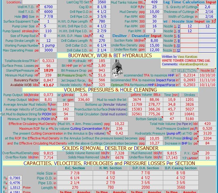
MUDWARE engineering software from M-I SWACO is a collection of mud- and drilling-related engineering programs and technical information provided free to the petroleum industry. This software contains most of the calculations typically used in the field while drilling and completing a well.

The 2,200-hp mud pump for offshore applications is a single-acting reciprocating triplex mud pump designed for high fluid flow rates, even at low operating speeds, and with a long stroke design. These features reduce the number of load reversals in critical components and increase the life of fluid end parts.
The pump’s critical components are strategically placed to make maintenance and inspection far easier and safer. The two-piece, quick-release piston rod lets you remove the piston without disturbing the liner, minimizing downtime when you’re replacing fluid parts.
REASON: This is the mud engineers Bible on the rig. It is based on prior knowledge of all drilling parameters and gives you a step by step plan for present well being drilled. It would guide you all though the drilling process.
Study your silos, pits, mud tanks, storage tank names, its contents, volume, dead volume capacity, properties of their contents (mud: especially Mud weight).
REASON: You don’t want to be taken unawares, you need to know the type of mud you have in each pit (where your backup mud is, kill mud if any, premix, etc.), you need to be sure you have enough mud to reach TD (Total depth) most especially if the logistics of transporting mud to the rig n’est pas facile, or takes days to arrive. Finally without knowing the properties of the mud you are introducing to the active system you would not be sure if what is affecting your active mud system is coming from the formation or from the mud you are introducing to the active mud.
REASON: You need to be sure the shaker screens can handle the flow if the mud is cold if not temporarily screen down to a lower size mesh or ask the driller to reduce the flow rate if permissible.
REASON: Drilling fluids would normally splash the rig crew on the rig floor while pulling and racking back pipes when a stand is removed from the drill string. So a slug (same mud but with 2-2.5 ppg higher density) would be prepared in the slug tank, and pumped into the drill string. This keeps the fluids level inside the drill pipe below the surface when tripping drill pipe.
For a leak off test (LOT), the mud has to be circulated to obtain uniform weight and condition. The primary concern for the mud engineer is to ensure an equal mud weight all through the mud. Mud weight going in to the hole should be equal to mud weight coming out of the hole at the shakers.
REASON: The well needs to be properly monitored. Instead speak with the mud loggers to convert the pit you want to transfer fluid from to the active system from a Reserve pit to an Active pit on their system then you can gradually make your transfers that way all volumes would be shown as active pit volume.
REASON: If the amount and average specific gravity of the solids in both fluids (i.e. the density) are different the mud weight would be a good indicator of the fluids interface during a displacement.
REASON: Calculate your hole volume, that means equal amount of mud on surface will leave you pit, so get the derrick man or personnel assisting you in the pit room to inform you when hole volume has been pumped.
REASON: Using a technique called nephelometry the turbidity can be measured. When light hits a particle the energy is scattered in all directions, it measures the level of light scattered by particles at right angles to the incident light beam. Initial NTU readings of both fluids would be the reference point for identification. After the Hi-vis passes through the driller should be told to stop pumping when the initial NTU of the filtered brine has been achieved.
For water based mud with a low alkalinity use phenolphthalein also. Add it to the mud and check for change of color to pink to know when traces of cement are on surface.
REASON: Note differences in weight between mud, spacer and cement before displacement of cement. The mud weight difference between the three fluids is a good indicator of the fluids interface on surface.
REASON: The first step is removal of cuttings from the borehole and the drilling fluid after which the mud should be condition before placing cement in the wellbore, either the density (not compromising well control) or the rheology depending on the situation. For the rheology, the yield stress, gel strength and plastic viscosity would be reduced hence reducing the driving forces necessary to displace mud with increased mud flexibility while being careful to prevent barite settling.
REASON: With no pit space to store the equivalent mud volume being replaced down hole, all pit levels should be recorded at all stages during the cement job. You would need to visit the pit room and return to the cement unit (while measuring cement density) at appropriate moments.
Measure all tank volumes before cement job i.e. when the mud has been thinned down and pump has been stopped (pit static). In case of leaks or valve mistakes all pits should be recorded.
If we get full returns during cementing it means that the cement displaced equal amount of mud and there was no loss down hole due to the cement job or due to displacement.
Prior to running casing, calculate the displacement of the casing first to know the volume it would displace, calculating from the mud line up to the casing depth.
REASON: From the cement program calculate the total volume of the fluids /cement that would be pumped into the hole that is not mud so as to confirm tank space to receive equal volume from the hole. If no available tank space/storage space then OBM should be back-loaded before the cement job to create space.
REASON: If it’s the pay zone, losses would require the use of acid-soluble LCM to prevent formation damage. Also considering down hole tools and motors, certain concentrations of LCM pills would not be pumped to avoid plugging/damaging the tools unless a bypass tool is part of the BHA.
Bit balling occurs in soft gumbo / swelling shales while drilling, the shale adsorbs water from the mud it then becomes plastic with a ball of compacted shale building up and covering the whole bit, stabilizers and drill collars, thus preventing further drilling progress.
To be certain it’s a bit balling issue we are dealing with the mud engineer should observe some of the following or collect the following information from the following rig personnel, with the first 3 information from the driller being very important:
Selecting a bit with a center jet “C”. Center jets are designed to help prevent bit balling by cleaning the cutters in larger diameter bits drilling soft formations.4
To prevent bit balling from occurring it is advisable to adopt procedures that worked in your geographical area in overcoming bit balling by always reviewing previous drilling mud report (DMR).
· Use mud system that can inhibit clay swelling example: Formulating KCl mud with PHPA (to avoid using higher concentrations of KCl) in which KCl prevents clay swelling while PHPA (partially hydrolyzed polyacrylamide ) coats the shales surfaces (encapsulates) thereby inhibiting their dispersion and incorporation into the mud.7
· “When drilling gumbo, the pH should be maintained at 9.0-10.0. If bit balling occurs, increase the mud alkalinity (PM) to 5 or more with lime”.8
· “If all else fails, before you trip out of the hole, you might pump a walnut-hull sweep. It will tend to sandblast the bit and remove the ball, and won’t hurt the mud. Don’t try this if you are running small jets in the bit, as plugging can be an issue.”11
A Drilling fluids Engineer should be able to observe or carry out a test and subsequently identify the reason for a high or a low mud weight in a water-base mud or an oil-base mud system.
Before looking at the reason why the mud weight reduced or increased from the given mud program specification, it’s good to know that the major function of drilling fluids is to provide sufficient pressure to check influx of gas, oil, and water into the well bore from the drilled formation.
The hydrostatic head of the mud column must be at least equal to that of the formation pressure, and hopefully greater, but not so high as to cause loss of circulation (except where an over balanced / under balanced drilling are specifically desired).
The mud weight materials could be barite, calcium carbonate or soluble salts such as sodium chloride (NaCl), potassium chloride (KCl) and calcium chloride (CaCl2). Sometimes the desired mud weight can be achieved by combining additions of salts and barite.
a. Mud Weight (Density) Test: The mud balance may indicate that mud weight is too high or too low. b. Retort Test: The test may indicate that the percent solids by volume is high, and your solids content calculations (lb/bbl low and high gravity solids) may indicate that barite content is too high or too low. c. Rheology tests: Indicates increase or decrease in viscosity
a. Increase in pump pressure: This can indicate an increase in Mud weight. b. Change in penetration rate: Increase in penetration rate may indicate decrease in mud weight while decrease in penetration rate may indicate increase in mud weight. c. Gas bubbles: This definitely indicates decrease in mud weight.

A mud/gas separator (poor boy degasser) sizing worksheet will assist drilling personnel with the sizing calculations. The worksheet provides a quick and easy evaluation of most mud/gas separators for a specific well application. A brief discussion of other mud/gas separator considerations is provided, including separator components, testing, materials, and oil-based-mud considerations. This paper reviews and analyzes existing mud/gas separator technology and recommends separator configuration, components, design considerations, and a sizing procedure. A simple method of evaluating mud/gas separation within the separator vessel has been developed as a basis for the sizing procedure.
The mud/gas separator (poor boy degasser) is designed to provide effective separation of the mud and gas circulated from the well by venting the gas and returning the mud to the mud pits. Small amounts of entrained gas can then be handled by a vacuum-type degasser located in the mud pits. The mud/gas separator controls gas cutting during kick situations, during drilling with significant drilled gas in the mud returns, or when trip gas is circulated up.
This paper discusses design considerations for mud/gas separators (poor boy degasser). The purpose of this paper is to allow drilling rig supervisors to evaluate mud/gas separators properly and to upgrade (if required) the separator economically to meet the design criteria outlined in this paper, and to provide office drilling personnel with guidelines for designing mud/gas separators before delivery at the drill-site.
The operating principle of a mud/gas separator is relatively simple. The device is essentially a vertical steel cylindrical body with openings on the top, bottom, and side, as shown in Fig 1. The mud and gas mixture is fed into the separator inlet and directed at a flat steel plate perpendicular to the flow. This impingement plate minimizes the erosion wear on the separator’s internal walls and assists with mud/gas separation. Separation is further assisted as the mud/gas mixture falls over a series of baffles designed to increase the turbulence within the upper section of the vessel. The free gas is then vented through the gas vent line, and mud is returned to the mud tanks.
Operating pressure within the separator is equal to the friction pressure of the free gas venting through the vent line. Fluid is maintained at a specific level (mud leg) within the separator at all times. If the friction pressure of the gas venting through the vent line exceeds the mud-leg hydrostatic pressure within the separator, a blow through condition will result sending a mud/gas mixture to the mud tanks. As one can readily see, the critical point for separator blow through exists when peak gas flow rates are experienced in the separator. Peak gas flow rates should theoretically be experienced when gas initially reaches the separator.
Three types of mud/gas separators commonly are used today: closed bottom, open bottom, and float type. The principle of mud/gas separation within each type of vessel is identical. Differences can be found in the method of maintaining the mud leg, as discussed below.
The closed-bottom separator, as the name implies, is closed at the vessel bottom with the mud return line directed back to the mud tanks, as shown in Fig. 1. Mud leg is maintained in the separator by installation of an inverted V-shaped bend in the mud return line. Fluid level can be adjusted by increasing/decreasing the length of the V-shaped bend.
Commonly called the poor boy,2,3 the open-bottom mud/gas separator is typically mounted on a mud tank or trip tank with the bottom of the separator body submerged in the mud, as shown in Fig. 2. The fluid level (mud leg) in the separator is controlled by adjusting the fluid level in the mud tank or by moving the separator up or down within the tank. Mud-tank height can restrict the maximum mud leg obtainable for open-bottom mud/gas separators.
Fluid level (mud leg) is maintained in a float-type mud/gas separator4 by a float/valve configuration, as shown in Fig. 3. The float opens and closes a valve on the mud return line to maintain the mud-leg level. Valves can be operated by a manual linkage system connected from the float to the valve, or the valve can be air-operated with rig air. Mud-leg height can be controlled by adjusting the float assembly.
There are some inherent problems in the use of float-type mud/gas separators. The manual linkage separator has experienced problems with linkage failure resulting in improper opening or closing of the mud-return-line valve. Air-operated valves fail to function if rig air is lost, resulting in no control of fluid level within the separator. Mud-return-line valves are prone to plug with solids, preventing mud flow-back to the mud pits.
Because of these problems, float-type mud/gas separators are not recommended and a closed-bottom separator is preferred. Open bottom separators are acceptable; however, one should be aware that they are restricted to a maximum mud leg, somewhat lower than the mud-tank height. Although float-type mud/gas separators are strongly discouraged, these separators can be modified easily for disconnection of the float, removal of the valve, and installation of a mud leg in the mud return line.
Table 1 shows a mud/gas separator worksheet to assist with the sizing calculation. The mud/gas separator illustrated in Fig. 4 will be evaluated for sufficient sizing in this paper.
Peak Gas Flow Rate. As discussed previously, the critical time for separator blow-through exists when peak gas flow rates are experienced. Mud/gas separator blow through is defined as inefficient separator operation resulting in a mud/gas mixture returning to the mud tanks through the mud return line.
Friction pressure of the gas venting through the vent line exceeds the mud-leg hydrostatic pressure, resulting in evacuation of fluid from the separator. Friction pressure of the mud through the mud return line is considered negligible because of its short length.
Vessel ID is too small, causing insufficient retention time for the gas to separate efficiently from the mud. This situation is commonly called insufficient’ separator cut.
Note that effective vent-line lengths will be significantly affected by the installation of flame arresters or some auto-igniters. The effect of this additional backpressure should be included in the calculation of vent-line friction pressure.
MudLeg. As previously discussed, mud-leg hydrostatic pressure must exceed vent-line friction pressure to prevent a separator blow through condition. Minimum mud-leg hydrostatic pressure would occur if an oil/gas kick was taken and the mud leg was filled with 0.26 psi/ft oil. 8 This minimum condition mayor may not occur, depending on the well location. Offset well data should be evaluated to establish a minimum mud-leg fluid gradient. For example, the 0.26-psi/ft mud-leg gradient would be considered extremely conservative if dry gas were expected for the sample problem. A more realistic estimate would approach the gradient of whole mud for the dry-gas case. A realistic mud-leg gradient for a gas/water kick would be the gradient of native salt water.
Separator ID. A blow-through condition may exist because a small vessel ID results in insufficient separator cut. Several complicated models exist to describe gas movement within a liquid.9 A simplified approach, taken in this paper, states that the gas migration rate upward within the separator must exceed the liquid velocity downward within the separator to give 100% separator cut and to prevent a separator blow-through condition. Gas migration rate is estimated at 500 ft/hr, or 8.4 ft/min,9 within the separator. This estimation is conservative and more realistic values would be higher; however, the slow gas migration rate serves as a worst-case scenario. Liquid flow rate through the separator can be estimated as 2xqk;for this paper 2×3=6 bbl/min. This factor of two was determined from gas volume at depth calculations (Boyle’s law) using Drilpro ™ for various depths and kick sizes. Correlation of the data shows that the mud flow from the well approaches twice the mud flow into the well (kill rate) for various kick sizes, kill rate, and wellbore geometries. A more accurate determination of mud flow from the well can be incorporated into the design procedure.
Note that a separator cut < 100% frequently exists with mud/gas separators, and under some conditions, is not a major concern. As stated earlier, the mud/gas separator is designed to provide effective separation of mud and gas with small amounts of entrained gas handled by a vacuum degasser located in the mud pits. Therefore, large active pit volumes may tolerate < 100% separator cut.
Sizing Conclusion. Having evaluated sizing criteria for the mud/gas separator (Fig. 4), we may conclude that the separator is sized sufficiently to handle our worst-case kick properly.
The effects of oil-based mud on the operation of the mud/gas separation can significantly affect sizing and design requirements. L These concerns are currently being evaluated. However, some conclusions can be made at this stage.
Gas kicks in oil-based mud that pass through the gas bubble point while being circulated from the well can experience higher Pcmaxand Vcmaxvalues than were calculated for a kick of the same initial pit gain in a water-based mud. This results in higher peak gas flow rates through the separator and thus the requirement for a more stringent separator design.
Gas kicks in oil-based mud that do not pass through the gas bubble point until the gas is downstream of the choke will severely affect mud/gas separator sizing and design. Peak gas flow rates will be extremely high relative to those calculated for water-based mud as outlined in this paper. Additional evaluation of the separator sizing should be completed if these well conditions exist.
Fig. 6 shows other separator components. A minimum 8-in.-ID mud return line is recommended for closed-bottom separators. Smaller lines may encounter problems with solids plugging the line. A larger-ID line would be considered beneficial. The impingement plate should be perpendicular to the separator inlet line and field replaceable.
Closed-bottom mud/gas separators should be designed with a minimum 1-ft sump at the bottom of the vessel. The sump will help prevent solids from settling and plugging the mud-return-line outlet.
A lower manway should be located on the lower part of the separator to permit sump cleanout or unplugging of the mud return line. The manway should be equipped with a replaceable rubber seal to prevent leakage.
The mud/gas separator should be equipped with a valved inlet on the lower section of the vessel to permit mud to be pumped into the separator. Mud can be pumped into the lower section of the separator during operation to decrease the possibility of solids settling in the mud return line. The valved inlet also permits cleaning solids from the lower portion of the separator, especially after separator use.
A siphon breaker or anti-siphon tube may be required to prevent having to siphon mud from the separator into the mud tanks, especially with configurations that require the mud return line to be extended below the separator elevation to allow mud to return to the mud tanks. The siphon breaker is simply an upward-directed open-ended pipe attached to the highest point of the mud return line.
New mud/gas separators should be hydrostatically tested to 188psi to give a maximum working pressure of 150 psi, as recommended by ASME. Periodic nondestructive testing should include radiographic examination of wall thickness and ultrasound verification of weld continuity. 12 At each initial hookup, every separator should be circulated through with water at the maximum possible flow rate to check for possible leaks in the connections. Frequency of testing should depend on anticipated and historical use of the separator.
Bracing the mud/gas separator has always been a major problem. When gas reaches the surface, separators tend to vibrate and, if not properly supported, can move, resulting in near-catastrophic problems. Thus, it is critical that all mud/gas separators be sufficiently anchored and properly braced to prevent movement of both the separator body and the lines.
Frequently, the situation arises where a mud/gas separator is picked up with the rig contract, and the drilling rig supervisor and engineer must evaluate the suitability of the separator for the well-location. This evaluation typically should be conducted during the rig bid analysis process. If the separator is insufficient or marginal, it may be more economical to upgrade the existing separator to meet the sizing criteria as an alternative to renting or building a suitable one.
Small Vessel ID. We frequently do our calculations and determine that our vessel ID is too small. Reducing the kill rate will improve this situation; e.g., if the kill rate for the previously sized separator were reduced from 3 to 1.5 bbl/min, then from Eq. 7: vL= [(2 x 1.5)/362]/1,029 =2.4 ft/min.
Thus, reducing the kill rate also reduces the liquid velocity rate in the separator, which increases the mud/gas retention time and improves the efficiency of mud/gas separation.
Also note that a gas migration rate of 500 ft/hr (8.4 ft/min) is a worst-case scenario and values could be higher. Therefore, when vessel ID is considered, a marginal separator probably would be sufficient because of this built-in safety factor. Higher gas migration rates may also be used in the sizing procedure, as previously discussed. Fig. 7 shows the effect of kill rate on the calculation of minimum separator ID for different gas migration rates.
Vent-Line Friction Pressure Exceeds Mud-Leg Hydrostatic Pressure.Another area of concern is vent-line friction pressure exceeding mud-leg hydrostatic pressure, Pj> Pml’Several options exist to help alleviate this problem.
Increase the mud leg. Another solution may be to increase the height of the mud leg. For example, if we increased the previously sized separator from a 7-ft mud leg to alOft mud leg, the mud-leg hydrostatic pressure should increase (Eq. 6).Pml=lOxO.26=2.6psi. Thus, the mud-leg hydrostatic pressure increased from 1.8 to 2.6 psi, allowing the separator to operate more efficiently.
Fig. 9 shows the effect of mud-leg height on the calculation of mud-leg hydrostatic pressure for different mud-leg gradients. Note that the mud-leg height cannot exceed the separator height. The mud leg may also be restricted by bell-nipple elevation. If the mud leg is higher than the bell nipple, additional surface equipment may be required to permit the separator to operate when drilling with significant gas in the mud returns.
Adjust vent-line bends. As shown in Table 1, the type and number of bends in the vent line significantly affect the effective vent-line length, which in turn affects the calculation for vent-line friction pressure. If we were to replace the targeted T-bends on the previously sized separator with right-rounded bends, the calculations for the effective length (Eq. 5) and vent-line friction pressure (Eq. 4) would change: Le=200+(3X 1)=203 ft and PI=(5.0x 10-12 x203x2,887,806)217.05 =0.5 psi.
Hence, a vent-line friction-pressure decrease from 1.0 to 0.5 psi increases the efficiency of the separator for a given mud leg. In addition, the vent-line friction pressure increases proportionally to the effective length (Fig. 10).
Increase vent-line ID. Increasing the vent-line ID is generally the most expensive alternative but may be the only adjustment possible to increase separator efficiency. Larger-ID vent lines will decrease the vent-line friction-pressure calculation. For the previously sized separator, if an 8.0-in.-ID vent line were used, the calculation for vent-line friction pressure (Eq. 5) would change to PI =(S.Ox10-12 X41OX2,887,806)217.05 =O.Spsi.
Again, a vent-line friction-pressure decrease from 1.0 to 0.5 psi will increase separator efficiency for a given mud leg. Fig. 11 shows the effect of vent-line ID on the calculation of vent-line friction pressure for the previously sized separator.
The principle of mud/gas separation within most commonly used mud/gas separators is identical. Differences can be found in the method of maintaining the mud leg.
A closed-bottom mud/gas separator is the preferred configuration. Open-bottom and float-type separators work well but are subject to limitations and prone to failure.


 8613371530291