
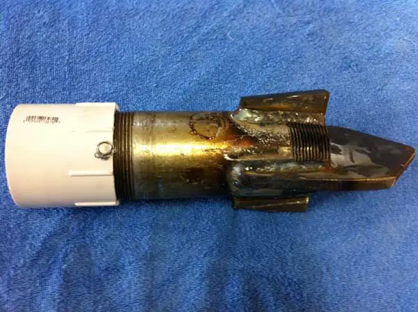
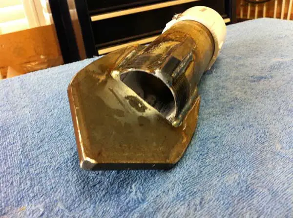
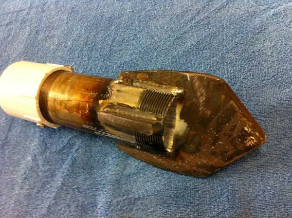
mud pump drill bit free sample
The 2,200-hp mud pump for offshore applications is a single-acting reciprocating triplex mud pump designed for high fluid flow rates, even at low operating speeds, and with a long stroke design. These features reduce the number of load reversals in critical components and increase the life of fluid end parts.
The pump’s critical components are strategically placed to make maintenance and inspection far easier and safer. The two-piece, quick-release piston rod lets you remove the piston without disturbing the liner, minimizing downtime when you’re replacing fluid parts.
There are many different ways to drill a domestic water well. One is what we call the “mud rotary” method. Whether or not this is the desired and/or best method for drilling your well is something more fully explained in this brief summary.
One advantage of drilling with compressed air is that it can tell you when you have encountered groundwater and gives you an indication how much water the borehole is producing. When drilling with water using the mud rotary method, the driller must rely on his interpretation of the borehole cuttings and any changes he can observe in the recirculating fluid. Mud rotary drillers can also use borehole geophysical tools to interpret which zones might be productive enough for your water well.
The mud rotary well drilling method is considered a closed-loop system. That is, the mud is cleaned of its cuttings and then is recirculated back down the borehole. Referring to this drilling method as “mud” is a misnomer, but it is one that has stuck with the industry for many years and most people understand what the term actually means.
The water is carefully mixed with a product that should not be called mud because it is a highly refined and formulated clay product—bentonite. It is added, mixed, and carefully monitored throughout the well drilling process.
The purpose of using a bentonite additive to the water is to form a thin film on the walls of the borehole to seal it and prevent water losses while drilling. This film also helps support the borehole wall from sluffing or caving in because of the hydraulic pressure of the bentonite mixture pressing against it. The objective of the fluid mixture is to carry cuttings from the bottom of the borehole up to the surface, where they drop out or are filtered out of the fluid, so it can be pumped back down the borehole again.
When using the mud rotary method, the driller must have a sump, a tank, or a small pond to hold a few thousand gallons of recirculating fluid. If they can’t dig sumps or small ponds, they must have a mud processing piece of equipment that mechanically screens and removes the sands and gravels from the mixture. This device is called a “shale shaker.”
The driller does not want to pump fine sand through the pump and back down the borehole. To avoid that, the shale shaker uses vibrating screens of various sizes and desanding cones to drop the sand out of the fluid as it flows through the shaker—so that the fluid can be used again.
Before the well casing and screens are lowered into the borehole, the recirculating fluid is slowly thinned out by adding fresh water as the fluid no longer needs to support sand and gravel. The driller will typically circulate the drilling from the bottom up the borehole while adding clear water to thin down the viscosity or thickness of the fluid. Once the fluid is sufficiently thinned, the casing and screens are installed and the annular space is gravel packed.
Gravel pack installed between the borehole walls and the outside of the well casing acts like a filter to keep sand out and maintain the borehole walls over time. During gravel packing of the well, the thin layer of bentonite clay that kept the borehole wall from leaking drilling fluid water out of the recirculating system now keeps the formation water from entering the well.
Some drillers use compressed air to blow off the well, starting at the first screened interval and slowly working their way to the bottom—blowing off all the water standing above the drill pipe and allowing it to recover, and repeating this until the water blown from the well is free of sand and relatively clean. If after repeated cycles of airlift pumping and recovery the driller cannot find any sand in the water, it is time to install a well development pump.
Additional development of the well can be done with a development pump that may be of a higher capacity than what the final installation pump will be. Just as with cycles of airlift pumping of the well, the development pump will be cycled at different flow rates until the maximum capacity of the well can be determined. If the development pump can be operated briefly at a flow rate 50% greater than the permanent pump, the well should not pump sand.
Mud rotary well drillers for decades have found ways to make this particular system work to drill and construct domestic water wells. In some areas, it’s the ideal method to use because of the geologic formations there, while other areas of the country favor air rotary methods.
Some drilling rigs are equipped to drill using either method, so the contractor must make the decision as to which method works best in your area, for your well, and at your point in time.
To learn more about the difference between mud rotary drilling and air rotary drilling, click the video below. The video is part of our “NGWA: Industry Connected” YouTube series:
Gary Hix is a Registered Professional Geologist in Arizona, specializing in hydrogeology. He was the 2019 William A. McEllhiney Distinguished Lecturer for The Groundwater Foundation. He is a former licensed water well drilling contractor and remains actively involved in the National Ground Water Association and Arizona Water Well Association.
When choosing a size and type of mud pump for your drilling project, there are several factors to consider. These would include not only cost and size of pump that best fits your drilling rig, but also the diameter, depth and hole conditions you are drilling through. I know that this sounds like a lot to consider, but if you are set up the right way before the job starts, you will thank me later.
Recommended practice is to maintain a minimum of 100 to 150 feet per minute of uphole velocity for drill cuttings. Larger diameter wells for irrigation, agriculture or municipalities may violate this rule, because it may not be economically feasible to pump this much mud for the job. Uphole velocity is determined by the flow rate of the mud system, diameter of the borehole and the diameter of the drill pipe. There are many tools, including handbooks, rule of thumb, slide rule calculators and now apps on your handheld device, to calculate velocity. It is always good to remember the time it takes to get the cuttings off the bottom of the well. If you are drilling at 200 feet, then a 100-foot-per-minute velocity means that it would take two minutes to get the cuttings out of the hole. This is always a good reminder of what you are drilling through and how long ago it was that you drilled it. Ground conditions and rock formations are ever changing as you go deeper. Wouldn’t it be nice if they all remained the same?
Centrifugal-style mud pumps are very popular in our industry due to their size and weight, as well as flow rate capacity for an affordable price. There are many models and brands out there, and most of them are very good value. How does a centrifugal mud pump work? The rotation of the impeller accelerates the fluid into the volute or diffuser chamber. The added energy from the acceleration increases the velocity and pressure of the fluid. These pumps are known to be very inefficient. This means that it takes more energy to increase the flow and pressure of the fluid when compared to a piston-style pump. However, you have a significant advantage in flow rates from a centrifugal pump versus a piston pump. If you are drilling deeper wells with heavier cuttings, you will be forced at some point to use a piston-style mud pump. They have much higher efficiencies in transferring the input energy into flow and pressure, therefore resulting in much higher pressure capabilities.
Piston-style mud pumps utilize a piston or plunger that travels back and forth in a chamber known as a cylinder. These pumps are also called “positive displacement” pumps because they literally push the fluid forward. This fluid builds up pressure and forces a spring-loaded valve to open and allow the fluid to escape into the discharge piping of the pump and then down the borehole. Since the expansion process is much smaller (almost insignificant) compared to a centrifugal pump, there is much lower energy loss. Plunger-style pumps can develop upwards of 15,000 psi for well treatments and hydraulic fracturing. Centrifugal pumps, in comparison, usually operate below 300 psi. If you are comparing most drilling pumps, centrifugal pumps operate from 60 to 125 psi and piston pumps operate around 150 to 300 psi. There are many exceptions and special applications for drilling, but these numbers should cover 80 percent of all equipment operating out there.
The restriction of putting a piston-style mud pump onto drilling rigs has always been the physical size and weight to provide adequate flow and pressure to your drilling fluid. Because of this, the industry needed a new solution to this age-old issue.
As the senior design engineer for Ingersoll-Rand’s Deephole Drilling Business Unit, I had the distinct pleasure of working with him and incorporating his Centerline Mud Pump into our drilling rig platforms.
In the late ’90s — and perhaps even earlier — Ingersoll-Rand had tried several times to develop a hydraulic-driven mud pump that would last an acceptable life- and duty-cycle for a well drilling contractor. With all of our resources and design wisdom, we were unable to solve this problem. Not only did Miller provide a solution, thus saving the size and weight of a typical gear-driven mud pump, he also provided a new offering — a mono-cylinder mud pump. This double-acting piston pump provided as much mud flow and pressure as a standard 5 X 6 duplex pump with incredible size and weight savings.
The true innovation was providing the well driller a solution for their mud pump requirements that was the right size and weight to integrate into both existing and new drilling rigs. Regardless of drill rig manufacturer and hydraulic system design, Centerline has provided a mud pump integration on hundreds of customer’s drilling rigs. Both mono-cylinder and duplex-cylinder pumps can fit nicely on the deck, across the frame or even be configured for under-deck mounting. This would not be possible with conventional mud pump designs.
The second generation design for the Centerline Mud Pump is expected later this year, and I believe it will be a true game changer for this industry. It also will open up the application to many other industries that require a heavier-duty cycle for a piston pump application.

Drilling mud—also called drilling fluid—is an essential component of the drilling process. Drilling mud aids in the process of drilling a borehole into the earth. Such holes are drilled for oil and gas extraction, core sampling and a variety of other purposes.
The fluid is used to lubricate the drill bit and transport the drill cuttings to the surface (U.S. Environmental Protection Agency, www.epa.gov). Drill cuttings are broken bits of solid material that are produced as the drill bit breaks the rock. As it circulates up from the drill bit, the drilling mud carries drill cuttings up to the surface, where the mud and the cuttings are separated.
Worldwide Recycling Equipment Sales says its Vulcan IDR 8440 delivers 20 MMBtu in its combustion chamber to remove contaminants from mud and cuttings. Source: Worldwide Recycling Equipment Sales LLC
After the drilling job is finished, the mud and cuttings must be disposed of in some way. The U.S. EPA classifies drilling muds as “special waste,” meaning that they are exempt from many federal regulations. As a result, laws concerning the disposal of drilling muds vary from state to state. The state of California, for example, has a strict set of regulations and requires operators to obtain approval before they may begin any sort of disposal (California Department of Conservation, conservation.ca.gov). Last year in Texas, an oil company had to pay a $1.35 million fine after drilling waste that was disposed of on their “landfarm” contaminated nearby water sources (Dave Fehling, State Impact, stateimpact.npr.org, Nov. 12, 2012). Landfarms are privately-owned, state-regulated fields where drilling waste is spread and, while they are legal, they can cause damage to the surrounding environment.
Throughout the drilling process, drilling mud is recirculated, which helps decrease waste by reusing as much mud as possible. When the drilling process is finished, the drilling waste must be disposed of in some way. Pit burial is a very common technique, in which the waste is placed in a man-made or natural excavation. However, burial is not a good method for waste that contains high concentrations of oil and industrial chemicals. The waste can easily contaminate soil and groundwater when the hydrocarbons and other chemicals leach into the earth, and polluted groundwater can take years or even decades to dissipate and often spreads to other areas.
Most water-based muds are simply disposed of after the drilling job is completed, but many oil- and synthetic-based muds can be recycled. Drill cuttings can also be recycled and reused, after the hydrocarbons are removed.
Recovered drill cuttings have numerous uses. They can stabilize surfaces that are more vulnerable to erosion, like roads and drilling pads. Cuttings can also be used as aggregate or filler in concrete, brick or block manufacturing. The U.S. Department of Energy has even researched the possibility of using drill cuttings as a substrate for restoring coastal wetlands, and some trials have been conducted in the United Kingdom using cuttings as power plant fuel (Drilling Waste Management Information System, http://web.ead.anl.gov/dwm/index.cfm).
Recovering drill cuttings and drilling muds is often practical and cost-effective, and is an environmentally sustainable process. The most efficient and successful way to remove volatile contaminants from muds and cuttings is thermal desorption. Indirect rotary kilns—like the Vulcan IDR 8440 from Worldwide Recycling Equipment Sales LLC—are ideal for recovering drill cuttings and drilling muds.
The Vulcan IDR 8440 also comes equipped with a vapor recovery system, which recovers vaporized hydrocarbons from the primary thermal desorption unit (PTU). The system is capable of recovering drill cuttings or up to 100 MMBtu per hour of energy for reuse as fuel, reducing the total operating cost and improving total return from projects.
Recycling drill cuttings and drilling muds can help operators meet disposal regulations, and the proper disposal of such waste prevents the contamination of water supplies and the soil. Through this process, muds and cuttings may be reused, saving money and contributing to the health of the environment.

A fast and efficient method of drilling, mud rotary drilling is effective in a wide range of geological formations, including sand, silt, clay, gravel, cobbles, and boulders. Not hindered by the presence of groundwater, a mud drill is also used for coring bedrock.
With the necessary torque for powerful rotation, new and seasoned operators find the Geoprobe® line of geotechnical drilling rigs and combination drilling rigs make for an effective mud drill thanks to:
With rig service shops in Pennsylvania, Kansas, and Florida, you’ll have industry-leading drill rig service support nearby for your routine maintenance or more in-depth rig remounting and refurbishment work - keeping your mud drill in the field earning dollars. Our service technicians are backed by our team of engineers to ensure solutions not bandaids to issues. And our production processes mean your mud drill is constructed consistently and tested thoroughly to ensure easier service support.
Engineered with efficiency and ease in mind, investing in a Geoprobe® mud drill simplifies your sampling while reliably ramping up production and rig utilization rates.
Our team of engineers thrives on collaborating with drillers while they continually innovate new designs for our mud drill line. Our goal is to make your job faster, safer, and easier. Partner with us and we"ll work to decrease your mud drill downtime while increasing your family time.

simulator provided by global simulator technology specialists Drilling Systems, will enable them to hugely expand their teaching capabilities in the field of oil
simulator provided by global simulator technology specialists Drilling Systems, will enable them to hugely expand their teaching capabilities in the field of oil

In the chip drilling process, dual concentrically arranged drill pipe are connected between a drill bit and a swivel with drilling fluid flowing to and from the bit in counter-current relationship in order to cool and lubricate the drill pipe and bit and to remove chips and other cuttings from the bottom of the borehole by circulating the cuttings to the surface of the ground where the cuttings subsequently may be studied by geologists in order to determine the physical and chemical properties of the strata of the earth through which the borehole has been formed. At the bottom of the borehole the drilling fluid picks up or entrains the chips and cuttings and transports them upwardly within the central pipe, or alternatively, transports them upwardly within the annulus formed by the drill pipe, where the cuttings ultimately flow to the surface of the earth, all of which is known to those skilled in the art; as evidenced by W.D. Elenburg, U.S. Pat. No. 3,439,757 to which reference is made for further background of the invention.
Heretofore it has been customary for others to flow connect the entire drilling mud flow stream from the borehole to a flow divider apparatus which separates the major flow stream into several flow paths so as to greatly reduce the volume of the drilling mud or chip bearing flow stream which is to be treated for subsequent analysis. Often the flow is improperly divided due to the physical characteristics of the solids and the mechanics of the flow divider, all of which results in inaccurate analysis of the borehole for the reason that one divided flow stream differs in composition or mixture from another divided flow stream. After the mud sample has been reduced in volume by selecting one of the flow streams for analysis, it is necessary to permit the solids to settle by gravity, after which the clarified water is siphoned off or decanted, and the remaining saturated solids or residue heated to evaporate the liquid therefrom.
It is therefore desirable to be able to split a stream of drilling mud containing samples from the chip drilling process into any desired fraction of the main flow stream wherein the smaller fraction of the main flow is identical in composition or mixture to the remainder of the flow. It is also desirable to be able to treat this fraction of flow in an improved manner which removes the solids therefrom, and to be able to relate the retrieved solid samples to the particular depth of the borehole from which the sample originated.
This invention relates to formation chip sampling method for separating solids from drilling mud which may be obtained from an earth boring operation so as to enable subsequent analysis thereof. As the drilling mud flows from the borehole, it exits at the swivel and flows to a separator where the air is removed therefrom. From the separator the flow continues to a splitter where a fraction of the flow is separated from the main flow. The fractional flow continues to a reservoir with the reservoir having fluid level control means associated therewith for supplying makeup water thereto in order to always maintain a fluid level therein. The contents of the reservoir is pumped under a positive pressure to a cyclone separator. The pump flow and the physical dimensions of the cyclone separator are sized with respect to one another so as to provide an optimum separation of solids from the liquid at the cyclone separator. Where deemed desirable, and especially when utilizing the chip drilling process, a screen may be interposed between the splitter means and the reservoir so as to reduce the load on the pump while at the same time maintaining large chips in an undamaged condition which will enhance the subsequent analysis thereof. The screened solids are combined with the solids removed from the cyclone separator and placed in a suitable container for storage or shipment.
A still further object of the present invention is the provision of a method by which formation chip samples are obtained from a chip drilling operation by improvements in separating solids from the drilling mud.
A still further object of the present invention is the provision of formation chip sampling methods which removes air from drilling mud, separates the drilling mud flow stream into a fractional part wherein the fractional part contains solids which are representative of the solids contained within the main flow stream, and which separates the solids from the liquid of the fractional component of the main stream.
Still another object of the present invention is a method of removing solids from drilling mud so as to provide a formation chip sample which can be related to the particular depth of borehole from which the sample originated.
As seen in the diagrammatical representation of FIG. 1, the present invention is used in conjunction with a borehole forming operation, broadly indicated by the arrow at numeral 10, wherein there is seen concentrically arranged drill pipe extending into the ground with the upper terminal end thereof being connected to a swivel 12. Drilling fluid, or drilling mud is pumped to the swivel in the usual manner while drilling fluid containing chips and particles of the formation being penetrated are retrieved at gooseneck 16. The gooseneck is flow connected to tangential inlet 17 of air separator means 18. The air separator has an upwardly depending centrally located conduit 19 from which air escapes. The air-free liquid flows through bottom outlet 20 and is directed into a splitter means 21.
The splitter includes a large outlet 22 which is flow connected to mud pit 23 by any suitable means, and to which the major portion of the flow is conducted. Small outlet 24 receives the remaining fraction of the drilling mud which is originally returned from the borehole. The remaining portion or fraction of the mud flows through screen 25 in order to remove large particles or chips therefrom. The fraction of the drill fluid which includes the smaller cuttings or particles which were not retained by the screen continues to flow on to the reservoir at 26. The upwardly opening reservoir has a sloped bottom to which a lower outlet is flow connected to pump means 27.
The pump can be actuated by any suitable means, as for example, a gasoline motor. The pump provides a high pressure flow to tangential inlet 28 of cyclone separator 29. As the drilling fluid flows through the cyclone separator, the liquid is separated from the remaining solids contained therein, with the liquid finally exiting at 30 where it can be flow connected to any suitable disposal means, as for example, the mud pit, while solids fall through lower outlet 31 where they are retrieved within any suitable receptacle 32. A source of makeup water (not shown) is connected to valve means 33 which in turn is controllably flow connected to a journaled float means 34 by the illustrated linkage. The float and valve assembly provides a level controller device for controlling the flow of make-up water into the reservoir so as to maintain a suction for the pump at all times.
FIGS. 2 and 3 show the details of the separator apparatus which includes a gear driven pump 27 having rubber impellers thereon and which is capable of producing a flow rate and pressure consistent with the design of cyclone separator 29 and to the mud flow rate into the reservoir.
The pump is driven by an internal combustion gasoline motor of the following described type: Wisconsin Engine, 3 × 31/4 size. The pump is of the following described type: gear driven, rubber impellers, capable of 40 g.p.m. at 9-15 p.s.i.g., manufactured by Booie. The inlet of the cyclone separator is provided with 40 g.p.m. flow rate. The separator is available from Kerbs Engineering, 1205 Crysler Drive, Menlo Park, California, Model D4B-12.
Looking now to the details of FIGS. 4 and 5, the before mentioned air separator 18 is seen to be in the form of a cylindrical tub having tangential inlet 17 connected to an upper extremity of the sidewall thereof; and with an upwardly depending reduced diameter air outlet 19 being provided at the upper end thereof. Outlet 20 is in the form of a downwardly and outwardly directed elbow which is arranged in overhanging relationship with respect to the splitter so as to cause the mud flowing therefrom to impinge against the rotating vanes of the splitter, as will be pointed out in greater detail later on.
In the embodiment set forth in FIGS. 6-8, the numerals used in conjunction therewith refer to similar numerals used in conjunction with FIGS. 1-5, wherever possible. As seen in FIGS. 6-8, mud from the drilling operation flows through air separator 118, which may be identical to the air separator of FIGS. 1-5. A screen 125 is interposed between the air separator liquid outlet 120 and the entrance of hopper or reservoir 126. The upper edge portion of the reservoir forms a support for the frame of the screen.
Valve 133 is actuated by float level device 134 in a manner similar to the arrangement of the level controller disclosed in FIGS. 1-5. Outlet 160 is connected to a bypass "T" 161, with the "T" having the illustrated valve therein for flowing mud to the mud pit. Valve 162 connects the "T" to pump 127, which in turn is connected to inlet 128 of separator means 129.
The liquid outlet 130 is freely received within the inlet elbow 163 of storage tank 165 with the outer peripheral wall surface of the outlet being spaced apart from the inner peripheral wall surface of the elbow. Overflow 164 can be flow connected to the mud pit, and is located below the inlet of the elbow so as to maintain the liquid height within the tank at a level which always leaves room for liquid flow from the separator. Outlet 166 is flow connected to the valve 133 of the liquid level control means.
In operation, drilling mud is circulated from a main mud pump (not shown), to the swivel where it is forced through the drill string annulus downhole to the drill bit, and back through the central passageway to the inlet 17 of the air separator. The formation samples cut by the action of the bit are in the form of chips and cuttings, and are transported by the drilling fluid into the air separator 18. The air separator can take on several different forms but preferably is similar to a centrifuge in that a vortex is established by the tangental inlet 17, thereby causing the drilling fluid to be separated from air contained therewithin. The air separator is especially useful where the chip drilling process is supplemented with air drilling, but is not considered indispensable to the process. As drilling mud exits from outlet 20, it impinges against the vertically disposed radiating vanes of the splitter, causing a rotational motion to be imparted into the rotor. Since the rotor is spaced apart from the wall of the stator and journaled at its upper and lower extremity, it will rotate at a r.p.m. or with a peripheral velocity which is dependent upon the flow rate of the drilling mud received therewithin. The major portion of the mud flow stream is free to flow through the spaced apart vanes at 47" and to the outlet 22, while a smaller fraction thereof is intercepted by the catch basins formed by the floor members 48.
As the mud flows through the spaced apart vanes 38, that is, the adjacent vanes which have no floor therebetween, it continues on through the rotor and into the lower extremity of the tub or stator where it then flows through outlet 22 and is directed to the mud pit 23. The smaller fraction of the drilling mud which flows into the catch basin, however, is trapped by the floor member and diverted through aperture 49, into the rotatable tubular member, and into fixed tubular member 45, where it then flows from lower chamber 50 and through outlet 24.
The number of catch basins 48 may be varied to provide any split desired, as for example, one sixty-fourth or one-half of the total returned mud flow may be deemed desirable as a feed rate into the reservoir 26. The number of catch basins determines the formation sample size as well as the load placed on the screen, reservoir, pump, and cyclone.
Since most chip drilling operations employ a fluid circulation rate of about 140 gallons per minute when making a 41/2 inch diameter hole, it is evident that the fraction of this amount which will be divided out by the splitter and received within the reservoir is dependent upon the ratio of catch basins to the open vanes. Since the pump 27 preferably receives exactly 40 gallons per minute, and assuming a 25 percent split, it is evident that the float 34 must open valve 33 a sufficient amount to supply 5 gallons of fresh make-up water per minute in order to maintain a fluid level within the reservoir.
Pump 27 delivers a constant flow of fluid to the cyclone separator, which can take on several different forms, and preferably is essentially a vertical cylinder with the usual inlet stream 28 being introduced tangentally near the top so as to give a spinning motion to the liquid traveling therethrough. The centrifugal force acting on the suspended solids tends to throw them radially to the side of the cyclone as the solids spiral downward to the conical bottom where they are removed at 31. The separated liquid is disposed of at the top, with the conduit 30 being a conventional outlet. With the cyclone separator operating within its most efficient range, essentially no liquid is lost through the solids outlet, and essentially saturated solids drop into the receptacle 32. It is for this reason that the pump 27 must always operate within its most efficient range, or otherwise the operation of the cyclone will not produce this desired effect.
The sample attained at 32 is related to the borehole depth by changing the screen 25 and receptacle 32 each five foot of hole, although other increments of penetration may be used where deemed desirable. Since the splitter divides out any desired portion of the returned mud, and since the divided portion of the flow stream is identical in composition to the remainder thereof, the present invention provides formation samples which are more representative of the strata being penetrated than has heretofore been possible to attain. All of the suspended solids passing the screen 25 are effectively separated from the liquid in a manner which obviates the necessity of decantation and evaporation treatment as has heretofore been necessary with prior art devices. By utilizing the present invention, each time the screen and receptacle is changed for the next five foot sample, it is now possible to immediately bag the obtained core sample and send it to the geologist. Accordingly, possible contamination of the sample is avoided since it is exposed a minimum length of time to the elements. This also avoids inadvertent interchange or mix-up of the samples.
In carrying out the invention in accordance with the embodiment disclosed in FIGS. 6-7, the large cuttings are obtained on screen 125 and combined with th centrifuged solids obtained at 132. The use of a splitter downstream of air separator 118 is considered optional, depending upon the flow rates involved. While making hole through known strata, the valve at 161 can be opened, while valve 162 is closed, so as to flow all of the mud to the mud pit, thereby leaving the pump and centrifuge inactive until they are needed.
When a mineral bearing strata is encountered, the valve at 161 is closed, the valve at 162 opened, and circulation through pump 127 initiated. Mud now flows into the air separator, through the screen, and into the reservoir. Make-up water flows from 166, 133 and through tangential inlet 167 where the side walls of the reservoir are cleaned of cuttings. The float at 134 maintains a fluid level within the reservoir which enables the pump to provide the separator means with a constant flow so as to achieve optimum efficiency of separation.
Since the overflow pipe 164 is located below the inlet elbow, the storage tank will overflow to the mud pit without affecting the liquid flow from the separator. Outlet 166 provides a constant source of make-up water to valve 133. Since the solids have been removed from the drilling mud, the only contaminate which can be contained within the make-up liquid is dissolved minerals. The reuse of this liquid is preferred to using make-up water which can be obtained from the mud pit for the reason that insoluble minerals are not recirculated through the system. Moreover, soluble minerals will be solublized at a slower rate as the recirculated make-up water dissolves a particular soluble element.
The specific splitter means together with the cyclone separator used herein is indespensible for handling ores which tend to float due to their surface tension and particle size. Material of this nature would otherwise be lost because they would float off to the mud pit in the absence of the present method.
While a particular pump and cyclone separator have been disclosed herein for purposes of illustration, it is pointed out that other pumps and other types of cyclone separators or centrifuge means may be used so long as the inlet pressure and flow rate to the cyclone separator is maintained within a range which prevents liquid from falling from the separator into the receptacle, and so long as carry-over of solids into the discharge is avoided.

Plan for the best and be ready to take corrective actions when your plans go wrong! This section of the tutorial is designed to help you solve the problems you will encounter when you drill wells. Don"t be discouraged.... use your common sense and learn what you can from the situation you are in! Common problems include:
Large amounts of make-up water is usually required and must be immediately available at all times when drilling in permeable sand and gravel. This is important because drilling fluid sometimes suddenly flows into permeable
If return circulation is suddenly lost, immediately switch the 3-way valve to direct the drilling fluid back to the pit through the by-pass hose (this minimizes the loss of valuable water). Then quickly pull-up the drill pipe 1-2 metres from the bottom of the borehole so that it is less likely to become jammed if the bottom portion of the hole collapses.
(Australian, 1992). A waiting period may allow the fluid to gel in the formation and provide a seal sufficient to allow circulation to be restored. If drilling has been proceeding with water or natural mud, replace the fluid with a thick bentonite slurry, circulate it down the borehole and let it sit for a while. When ready to circulate back
If waiting and thickening the drilling mud do not restore circulation, question why the circulation was lost. If the drilling fluid is being lost into a highly permeable saturation formation, it may be possible to construct an excellent well! Therefore, test the well yield before deciding to proceed with the steps outlined below.
If it is necessary to drill further, try adding thickening materials to the drilling mud. This may occur when extremely unstable formations or those containing open fractures are encountered. Almost any granular flake or fibrous material can be used to provide a wad to block a lost circulation zone. Local materials such as bran, husks, chaff, straw, bark, wood chips, cotton, feathers, or even fibre or wool bedding can usually be located readily and used (Australian, 1992). This material should be pushed down the hole and allowed
The "gunk squeeze" method of sealing off a zone of lost circulation involves forcing a large amount of clay or cement into the zone of water loss (usually at or near the drill bit) and forcing it into the formation where it swells and fills-up any cracks (Australian, 1992). The best way is to mix a very high concentration (6 - 7 kg/L) of bentonite. Once mixed, immediately lower it into the borehole in a sealed bag or container which can be ruptured when opposite the lost circulation zone. This material can be forced into the formation by pressurizing the borehole or by pushing it with a block on the end of the drill string.
If the lost circulation zone cannot be blocked, drilling sometimes may proceed without return circulation. The cuttings are carried away into the formation cavities. It may be necessary to occasionally pump a slug of thick mud to clear the bottom of the hole (Australian, 1992).
Alternatively, casing can be placed to seal-off the problem zone. Ensure that the hole has fully penetrated the problem zone which is to be protected by the casing; Running the casing too soon may not overcome the problems for long. Finally, if none of these options work, it may be necessary to abandon the hole or to continue drilling using a air rotary drilling machine (Australian, 1992).
The main cause of borehole caving is lack of suitable drilling mud (see Section 5). This often occurs in sandy soils where drillers are not using good bentonite or polymer. The problem can be seen when fluid is circulating but cuttings are not being carried-out of the hole. If you continue to push ahead and drill, the bit can become jammed, the hole will collapse when you try to insert the casing or a huge portion of the aquifer may wash-out making it very difficult to complete a good well. The solution is to get some bentonite or polymer or, if necessary, assess the suitability of natural clays for use as drill mud (see Appendix H).
Borehole caving can also occur if the fluid level in the borehole drops significantly (see Footnote #1). Therefore, following a loss of circulation or a night time stoppage, slowly re-fill the borehole by circulating drilling fluid through the drill pipe (pouring fluid directly into the borehole may trigger caving). If caving occurs while drilling, check if cuttings are still exiting the well. If they are, stop drilling and circulate drilling fluid for a while.
Sometimes part of the borehole caves while the casing is being installed, preventing it from being inserted to the full depth of the borehole. When this occurs, the casing must be pulled out and the well re-drilled with heavier drilling fluid. When pulling the casing, no more than 12.19 m (40 ft) should be lifted into the air at any time; more than this will cause thin-walled (Schedule 40) PVC to bend and crack.
The drill pipe and bit may become jammed when the drilling fluid is not allowed to thoroughly clean the borehole prior to stopping to add another joint of drilling pipe or the fluid is too thin to lift gravel from the bottom of the borehole.
Therefore, if the drill bit starts to catch when drilling, stop further drilling and allow the drilling fluid to circulate and remove accumulated cuttings from the borehole. Then continue to drill at a slower rate. If it continues to catch, thicken the drilling fluid.
If the drill bit and pipe become jammed, stop drilling and circulate drilling fluid until it is freed. If circulation is blocked, try to winch the bit and pipe out of the borehole. Stop the engine and use a pipe wrench to reverse rotation (no more than 1 turn or the rod may unscrew!). Rapidly hit the drill pipe with a hammer to try and jolt the bit free.
If these actions are not successful, use lengths of drill pipe without a bit attached or Wattera tubing to "jet out" the cuttings. Attach the pipe or tubing directly to the discharge hose from the mud pump. Thicken the drilling fluid to ensure that the cuttings holding the bit can be removed. Then place tension of the stuck pipe with the drill rig
winch. Once fluid starts to circulate out of the borehole, slowly push the jetting pipe/tubing down the borehole beside the jammed drill pipe until the bit is reached. When fluid starts to circulate out of the stuck pipe and/or it loosens, pull the stuck drill pipe and resume circulation of the thickened drilling fluid back down the drill pipe and bit. Remove the jetting pipe. If water freely circulates out the borehole, slowly lower the drill pipe and bit and resume drilling.
Unfortunately, sometimes wrenches, rocks etc are inadvertently dropped into the borehole when drilling. In addition, the LS-100 is often operated near its design limits with a high degree of structural stress on the drilling stems
and tools; encountering unexpected layers of very soft sand or filter or hard rock can cause cave-ins or tool breakage and all the drill pipe can be lost in the hole.
If objects are dropped into the borehole after the final depth has been reached, it may be possible to leave them there and still complete the well. If this is not the case, it may be possible to make a "fishing" tool to set-up on the lost gear. For example, if a length of well screen falls down the borehole, it may be possible to send other sections down with a pointed tip on the end and "catch" the lost casing by cramming the pointed end hard into it. These types of "fishing" exercises require innovation and resourcefulness suitable to the circumstances - there is no single right way of doing this work. If sediment has caved in on top of the drill bit or other tools, circulation should be resumed in the hole and the fishing tool placed over the lost equipment.
If the lost tools/bit(s)/drill pipe are not critical, do not even try to retrieve them and just move over and start drilling a new hole. Even if the equipment is important, it is still best to start drilling at a new location while others try to retrieve it since considerable time can be spent on retrieval and there is a low likelihood of success.G-6: Resistant Beds Encountered
Once a resistant bed is encountered and the rate at which the drill bit is penetrating the formation drops dramatically, a decision needs to be made whether to stop drilling or to continue. If the resistant bed is comprised of gravels, the drilling fluid may need to be thickened to lift-out the cuttings. If the resistant bed is hard granite, drilling with the LS-100 should cease. Other drilling methods should be found or drilling should be attempted at another location. Remember, to help as many people as possible and to get the best value for donor dollars, DRILL THE EASY BOREHOLES FIRST!! It is not worth wearing-out the equipment by grinding away for hours and hours to gain a foot or two of borehole depth.
It is sometimes necessary to drill through aquifers which contain contaminated water. In these situations, drill until a confining layer (clay or rock) is encountered. Insert the casing and then seal the annular space with a grout slurry. To avoid damaging the grout seal, let the grout cure for at least 12-24 hours prior to resuming drilling
Cement grout is normally placed by just pouring it into the annulus. Alternatively, some grout could also be poured into the casing and/or the casing could be raised several feet and then pushed into the grout that accumulates at the bottom of the borehole. Place the grout in one continuous operation to form a good seal (Driscoll, 1986). Since irregularities in the size of the borehole and losses into formation may occur, the driller must be prepared to augment initial estimates of grout volume on short notice.
Sometimes the water in a confined aquifer is under so much pressure that it will flow out the top of a well which is drilled into it. Special precautions and construction techniques must be used to control the water pressure and flow or serious environmental problems can result. The free flow of excess water to waste can result in the depletion of a valuable resource and in unnecessary interference with other well supplies. Free flow from the well casing or a breakout of uncontrolled flow around the well casing can cause serious erosional and flooding problems on the owner"s and adjacent properties that may be very difficult and costly to correct.
Sometimes natural flow can be brought under control by extending the well casing 1.5 - 6 m (5 - 20 ft) into the air. This can allow the pressure in the pipe to balance that within the aquifer. A spout with a tap can then be installed in the side of the casing. A hand pump can be installed at a later date if the pressure in the pipe drops over time.
Sometimes a very thin or relatively impermeable aquifer is encountered which must be developed to provide a reliable water supply. Ensure that the borehole penetrates the full thickness of the aquifer, extending as far below it as possible. Install the well screen adjacent to the entire aquifer thickness with solid casing installed above and below it. After developing the well, install the pump cylinder as low as possible in the well.
If a well is being completed in a fine sand/silt aquifer within 15-22 m (50 - 75 ft) of ground surface, a 20 cm (8 in) reamer bit has sometimes been used (e.g. Bolivia). This makes it possible to install a better filter pack and reduces entrance velocities and passage of fine silt, clay and sand particles into the well.
Yield can be maximized by adding a small amount of a polyphosphate to the well after it has been developed using conventional techniques. The polyphosphate helps remove clays that occur naturally in the aquifer and that were introduced in the drilling fluid (see Footnote #3).
To avoid these problems, minimize the amount of pull-down pressure when drilling so that the bit can run freely under its own weight. Also, casing there is no problem with casing jambing when 7.6 cm (3 in) schedule 40 casing is used. Keep in mind, however, that a 7.6 cm (3 in) casing is too small to take a 6.4 cm (2.5 in) pump cylinder or most submersible pumps. Usually, however, these issues are not a concern.
If you need to construct a 10 cm (4 in) well and the casing has jammed, the best solution is to pull the casing / screen from the borehole. This involves cutting the casing into 6-12 m (20 - 40 ft) lengths (longer than this will result in the casing bending and cracking). Slowly re-drill the borehole with a 15 cm (6 in) reamer bit or, if available, a 18 or 20 cm (7 or 8 in) bit. Concentrate on the portion of the borehole where the casing jammed. While this can take several hours, it often eliminates blockages and allows the casing to slide to the bottom of the borehole. As soon as the reaming is completed, re-glue and re-insert the casing.
If it still jams, your last resort is to try and "wash" the casing down by installing the drilling rods down inside the casing and circulating drilling fluid through a wash-down valve (see Section 7). Fluid is pumped down through the casing and out the bottom of the screen where it will pick-up and carry soil particles back up to the surface between the casing and the hole walls. The amount of water passing through the screen openings can be minimized by attaching a surge block to the lower end of the drill string. Be sure to secure the pipe with a rope to prevent the casing from dropping if the blockage was localized and is removed with the circulation process. Failure to do so could result in the casing dropping to the bottom of the hole without the casing extending to the surface. When the casing is finally installed to the appropriate depth, stabilize the open bottom
A well can suddenly no longer provide the same amount of water that it did before. If you move the pump handle and it feels OK but little or no water comes out the spout, the well may be dry. Confirm this by measuring the water level in the well and try to determine which of the following causes is responsible:
Natural Lowering of the Water Table: Water levels in shallow dug and bored wells experience large fluctuations due to climatic conditions. The natural seasonal change in water level often will often be several metres. This is likely the cause of the drop in yield if the level of water within the well does not rise up, even several hours after pumping. All that can be done is to construct a new well, ensuring that the well casing is set far enough below the water table (ideally 5 to 10 metres) to assure an adequate water supply during the dry summer periods when the water level declines. Also, check how many people are drawing water from the
Screen Blockage: Sometimes the problem is that the well screen has plugged-up with fine sand and silt particles, with accumulated iron deposits or with growths of nuisance bacteria (naturally occurring, non-health related bacteria with can produce rotten egg smells, random slugs of iron rich water etc). This is likely the case if the water level in the well is near its original construction level but drops to the bottom of the pump cylinder as soon as the well is pumped. The well should be extensively re-developed to try and restore the efficiency of the screen and gravel pack (see
1 The drilling fluid prevents caving of the borehole because it exerts pressure against the wall. As long as the hydrostatic pressure of the fluid exceeds the earth pressures and any confining pressure in the aquifer, the hole will remain open. The pressure at any depth is equal to the weight of the drilling fluid column above that point.
2 Before drilling out the grout plug, the effectiveness of the seal can be checked by measuring water-level change in the casing over time. In wells with a low static water level, the casing can be filled with water or drilling fluid and later checked for any water loss. If the static water level is high, the casing can be nearly emptied and any influx of water into the casing can be measured.
L (100 gal) of water in the screen. 0.9 kg (2 lbs) of sodium hypochlorite should also be added to every 100 gal of water in the well to control bacterial growth promoted by the presence of polyphosphates (Driscoll, 1986). Polyphosphates should be premixed before introduction into the well because they do not mix easily with cold water. Occasionally the mix water is heated to help dissolve the chemical (Driscoll, 1986). Polyphosphates should NOT be used in formations with thinly bedded clays and sands because these chemicals tend to make the clays near the borehole unstable, causing them to mix with the sand (Driscoll, 1986) continually passes into the borehole during pumping (Anderson, 1993).
5 When a well is pumped, the water level in the immediate area of the well is lowered and a cone of depression develops around the well. The size and the shape of the cone will depend on the aquifer characteristics of the water-bearing formation in which the well is completed and the rate of pumping. This is likely the cause if there are two or more wells located within 100 m of each other and if water levels return to normal in both wells once pumping has stopped or within some reasonable time afterwards. Water level recovery depends on the quantity of water withdrawn from the aquifer and the length of time the wells were pumped. All that can be done is
Australian Drilling Industry Training Committee Ltd (1992) Australian Drilling Manual 3rd edition", Macquarie Centre: Australian Drilling Industry Training Committee Ltd, ISBN 0-949279-20X.

Owners praise their Geoprobe® 3126GT geotechnical drill for its simplicity and safety so new drillers quickly travel the learning curve. Veteran drillers appreciate the attention to features addressing their field needs. Together all the standard features and available options minimize operating costs and come in at a price point lower than you might anticipate.
ENGINEERED FOR EFFICIENCY: with six functions along the centerline, use machine hydraulics and controls to side-shift the head, simplifying your geotech applications. Complete augering, mud rotary, SPT, Shelby tubes, hard rock cores, CPT — even direct push — without manipulating mast position or mobilizing multiple machines.
ENHANCED EASE AND SAFETY: boost geotechnical drill output and utilization with hands-free automatic drop hammer and integrated CPT head-feed rate control, including cone overload protection. Leverage small footprint to expand site access without sacrificing flow from mud pump or accessory storage. Bring new drillers up the learning curve quickly with easy controls and integrated safety features built to internationally-accepted standards.
ELEVATED SERVICE AND SUPPORT: respond to your clients needs, making a quick call to get answers to your field and geotechnical drill service questions with overnight part shipping available from industry-leading support team.
With drill rig service shops in Pennsylvania, Florida, and Kansas, you’ll have service support nearby for your routine maintenance or more in-depth drill rig remounting and refurbishment work. Our service technicians are backed by our team of engineers to ensure solutions not bandaids to issues. And our production processes mean your geotechnical drill is constructed consistently and tested thoroughly to ensure easier service support.
Six functions along the 28-inch centerline head side shift simplify traditional geotechnical applications — augering, mud rotary, SPT, Shelby tubes, hard rock cores, CPT – and even direct push. Features GH63 percussion hammer 4-speed rotary head with 4,000 ft-lb, DH104 hands-free automatic drop hammer, CPT push/pull assembly, and a rod grip pull system. Head shifting speeds up drilling and minimizes the time driller spends in danger zone.
Drill mast features extend, swing, mast dump, oscillation, and fold. Mast dump provides 36.5 inches of vertical travel to allow room for a mud pan. Optional outriggers available.
Hands-free rotary and head feed controls on the 3126GT reduce strain on driller when completing applications like mud rotary. CPT feed rate and hydraulic limit functions are standard.
"This reduces the transport height of the 3126GT from 114 inches to 99 inches," Ryan Kejr, machine engineer lead, said. "We accomplish this with a simple, mechanical ratcheting actuator. This is easily accessible from the ground when the drill mast is in transport position."

When you"re seeking the field flexibility to complete your drilling faster, easier and safer, count on Geoprobe® drill rigs engineered for versatility and manufactured for reliability. Industry leaders depend on our ongoing commitment to innovation and industry-leading customer support to advance their business ahead of the competition. Digital readouts providing instant feedback, enhanced safety features, easy operation, and availability of training options mean veteran drillers find their jobs simplified while new drillers build confidence, making them productive as they"re quickly coming up the learning curve.
Whether you’re facing consolidated materials, glacial till, or backfill rubble, quickly complete complex holes to greater depths with the powerful GV5 50K sonic head on our line of sonic drill rigs. Engineered by Geoprobe® to advance up-to 12-inch tooling, the GV5 produces torque required to maintain rotation in tight formations – all backed by a 2-year warranty.
Increase depth advancement and recovery speeds while minimizing waste with the 8150LS sonic drilling rig engineered for driller safety, sampling speed, and operation efficiency.
Geoprobe® combination drill rigs possess the power to tackle difficult site conditions combined with the versatility to exceed subsurface sampling expectations to equal business growth in both direct push and rotary drill rig applications.
Combine geotechnical augering and high-speed rotary with advanced direct push capability to offer additional services to your customers, quickly going from coring rock to pushing CPT - all in one drill rig.
From crowded street corners to far removed places, tackle various environmental, geotechnical and exploration applications with a single machine combining rotary drilling and direct push, saving time and money required to mobilize multiple drill rigs.
In a geotech industry ruled by rate-per-foot, Geoprobe® geotechnical drill rigs capable of swiftly sliding from rotary to automatic drop hammer, even to CPT or direct push — without having to move drill mast or machine — position you for increased production and profit.
Save time and effort swiftly sliding the innovative centerline head side shift into position for rotary, automatic drop hammer, event CPT or direct push. No need to move the geotechnical drill or drill mast on the compact, off road drill rig.
Punch out power and pipe line projects with efficiency and performance of 31 series drill mast aligning all head and winch functions over the bore hole combined with creature comforts of a crawler carrier.
Efficiently complete geotech investigations sliding between drilling functions all without the need for a class A/B CDL, safely bringing new drillers up the learning curve on the drilling truck.
Maximize the value of your investment by choosing a CPT drilling platform best suited to your specific business model. Whether you’re seeking a dedicated CPT drilling rig or a versatile drilling rig to run a variety of applications, you’ll find the combination of features to push your business ahead.
Generating a name for itself and redefining the way sites are investigated in the environmental industry, Geoprobe® continues to advance direct push drilling through continued innovation of its line of high-quality, hydraulically-powered direct push drilling rigs
Featuring a proven GH63 percussion hammer and able to use 5-foot tooling, the 6011DT direct push drill rig is still being sized to slip into small spaces.
With the necessary tophead rotation speed, head feed speed, and plenty of mud pump options to get the job done, complete your water well drilling, geothermal drilling, and cathodic protection drilling jobs with a single, compact water well drill.
Tophead offering both torque and speed to the impressive power to weight ratio make the DM450 well suited for water well, geothermal, and/or cathodic protection drilling while minimizing maintenance.
Outfit as down the hole drill or mud drill with the power of 28.5-foot stroke, 40,000 lb pullback, and 8,000 ft-lb torque to handle deeper wells along with weight of steel casing.

Directional drilling is a broad term used to describe any boring that doesn’t go in a straight line vertically down. In fact, even in a vertical well, it might be necessary to deviate to avoid a geological formation or a previous stuck pipe, then return to the original path. In this instance, the driller uses sidetracking techniques.
In conventional drilling for oil and gas, the drill bit, drillstring, pipe and casing all go down in a straight line. If a driller aims away from the 180-degrees down, that’s technically directional drilling. Nowadays, however, it’s more likely that there’ll be a series of one or more carefully planned directional changes along the wellbore.
Directional drilling techniques have been employed for almost 100 years now. Over the past few decades, technological improvements have meant that angles, turns and underground distances covered are amazing feats of engineering.
Techniques such as multilateral, horizontal and extended reach drilling (ERD) are enhanced oil recovery (EOR) methods that can increase the yield of a downhole dramatically. It’s possible for ERD specialists to drill for more than 10 kilometers/6.2 miles. Students of petroleum engineering often get shown illustrations and diagrams that look like tree roots. If we imagine the rig as the trunk of the tree, the directional possibilities of the roots are endless. Even the branches of the roots are comparable to multilateral drilling.
Multiple down holes can be drilled from the same rig, minimising surface disturbance and environmental impact. Also, these boreholes can extend up to a mile down, and for more than five miles at shallower angles. In an oilfield with dispersed deposits, a large radius can be tapped, maximising the expensive asset which is the rig. Rigs and crews have day rates that run into the hundreds of thousands of dollars, one rig working up to five or ten square miles is very cost-effective in comparison to having a dozen or more vertical rigs, which may or may not be tapping into the same accessible reservoir deposits.
On top of this randomness related to upper, lower and outer dimensions, there are plenty of other possibilities:By drilling at an angle, more of the reservoir gets explored, since they tend to form horizontally (between formations) not vertically.
The deposit might not resemble a reservoir at all, it might be oil-saturated sand or shale. Directional drilling is especially valuable in shale, where the formation can be explored to follow richer seams.
It’s common to find deposits below salt domes or fault planes, where the driller faces increased technical risk. Horizontal drilling can avoid salt domes, and reduce pressure on equipment near fault lines.
In fact, these ‘irregular’ reservoirs are very common. Now that relatively fewer elephant reservoirs are being discovered, and technology improves, directional drilling becomes more critical each year.
Another use for directional drilling is in the event of an uncontrolled, or ‘wild well’. If you imagine a well that has broken through the blowout preventer and is gushing, how can you cap it?
This depends on the amount of underground pressure. In some instances, a second control well is drilled so that it intercepts the same point where the original wellbore meets the reservoir. Once the new directional well is completed, it can be pumped with kill fluid.<


 8613371530291