
mud pump flow loop factory

Top-Co’s engineering team is focused on the R&D of new products, often in response to operating challenges encountered by customers. The engineering team, populated with professionals with experience in this sector, employs electronic design media and 3-D modeling to facilitate precise and quick designs. In-house testing validates new or improved products prior to field introduction. Upgraded state-of-the-art test loop equipment currently is being installed, ensuring that existing and modified float equipment consistently complies with API IIIC specifications.
Commissioned in 2009, Top-Co’s flow loop testing facility is designed to foster standard and creative testing for a number of its tools. In addition, a goal has been to close the cycle from identifying a product requirement to achieving complete customer satisfaction.
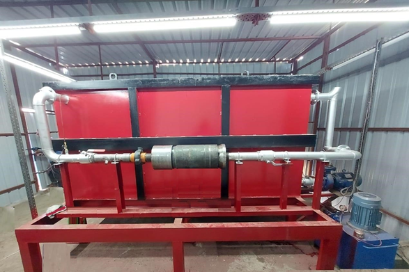
Top-Co’s facility features a tank with a storage capacity of 160 bbl and has two agitators used in combination with the tank’s shape to avoid sagging of the weighting material in the drilling mud. Mud is pumped with a centrifugal pump capable of delivering up to 22 bbl/minute at approximately 140 psi. Heat blankets in the pipes can be set to 600 ºF while circulating the mud to increase its temperature to the test requirements. (Images courtesy of Top-Co Primary Cementing Equipment)
The tank has a storage capacity of 160 bbl and has two agitators used in combination with the tank’s shape to avoid sagging of the weighting material in the drilling mud.
Mud is pumped with a centrifugal pump capable of delivering up to 22 bbl/minute at approximately 140 psi. Heat blankets in the pipes can be set to 600 ºF (316ºC) while circulating the mud to increase its temperature to the test requirements.
The flow rate is measured continuously by a flowmeter installed at the exit of the test bench and is controlled by varying the speed of the centrifugal pump. The flow loop has three thermometers measuring mud temperature. One is installed in the tank and is used mainly during mud warmup prior to starting a test. The other two are installed in the inlet and outlet of the test bench and allow for full compliance with test temperature requirements by API RP 10F, independently of heat loss due to a lower ambient temperature.
The flow rate is measured continuously by a flowmeter installed at the exit of the test bench and is controlled by varying the speed of the centrifugal pump. The pump’s motor speed is, in turn, controlled by a variable frequency drive that reacts to the flowmeter’s measurement, adjusting the pump speed as required to maintain the specified flow rate. This setup allows for a stable constant flow rate to be maintained during testing.
The flow loop has three thermometers measuring mud temperature. One is installed in the tank and is used mainly during mud warmup prior to starting a test. The other two are installed in the inlet and outlet of the test bench and allow for full compliance with test temperature requirements by API RP 10F, independently of heat loss due to a lower ambient temperature. This is of importance during tests conducted in winter.
A parameter in the testing of float equipment is what API calls “volume required to achieve valve closure,” which the facility can accurately measure by collecting backflow in graduated buckets sitting on calibrated weight scales. The weight measurement is used in combination with the latest rheological properties to calculate the volume. The combination of leak weight and visual observation allows the operator to identify minimum amounts of backflow (dripping). In a real application, a valve leaking a very small amount could go undetected for days or weeks when the plug is found higher than expected.
The flow loop is equipped with 22 pressure measurement locations connected to a data acquisition system capable of recording up to 100 readings/second. A benefit of this system is the flexibility in the types of tests it allows, in addition to standard API tests. All instruments in the facility are subject to a strict calibration schedule that also is part of the plant’s quality management system.
The facility’s pumps and valves are actuated from the control software, allowing for a complete test to be run entirely from the computer. To minimize operator impact on the test results, an investment was made to build subroutines into the software that guide the operator through the test procedure. This improves the speed at which tests are conducted and increases the repeatability of results.
In anticipation of the longer reach and deeper wells in the coming years, Top-Co also has initiated tests under more demanding conditions such as higher flow rates and longer circulating times. This is most relevant in extended-reach wells, where fluid particle velocities required for appropriate hole cleaning may be as high as three to five times those of vertical wells and take longer to clean. For deeper wells, higher differential pressure capabilities may be expected and, therefore, testing above 5,000 psi also is required. Top-Co is using this capability in testing on destruction and development of new high-pressure products.

During drilling in Oil and Gas exploration, drilling mud or Bentonite is pumped into boreholes for multiple reasons. Pumping drill mud into boreholes cools the drill bit as well as bringing drill cuttings to the surface as the way in which mud is pumped into boreholes forms a closed loop system. The use of drilling mud also provides hydrostatic pressure to prevent liquids such as oil and gas rising to the surface, as drilling mud is thixotropic meaning when it is not agitated it stiffens forming a mud which is an effective liquid and gas barrier.

Our in-house testing cell includes the Flow Loop Testing Facility. Our Flow Loop Testing Facility plays a key role in estimating how to float equipment performs under various conditions in the field.
• The Flow Loop Tank is fitted with two agitators to ensure that fluid remains well mixed. These agitators also prevent the sagging of the weighting material in the drilling mud.
• Two flow meters are installed at different locations to ensure continuous measurement of the flow rate. The pump’s speed is adjusted to maintain the flow rate as per test requirements.
makes it possible to run the entire test from the computer reducing the operator’s impact on test results. This system is set to record readings every 20 seconds. Real-time readings of all the flow transducers and pressure transducers are displayed on the screen when the test is being conducted.

Centerline Manufacturing is committed to the highest level of customer service quality. Every Centerline pump is comprehensively and repeatedly tested at diverse pressure levels to assure that it goes to our customer in perfect operational order. Centerline technicians work to ensure that our customers fully understand the operation of the model being delivered. If a customer"s pump is down, we understand the importance of timely response and parts availability. Centerline technicians will assess the problem and make repairs to bring the pump back into new specification. The Centerline mud pump technicians are well versed and qualified to operate and repair any product that is provided to the customer.
Closed loop pressurized freshwater liner wash system, complete with integral water cooling tank equipped with centrifugal pump and driven by explosion proof electric motor
Belt drive transmission: two each motor sheaves and QD mounted pump sheaves; banded Kevlar Vbelts; belt guards; for use with AC drive motors c/w 20HP blower assemblies

Theoretical transport of drill cuttings in an oil well is well understood. Textbooks illustrate common flow patterns and methods to mitigate cuttings transportation problems. When cuttings are not removed from the oil well as quickly as they are produced, stuck pipe and well control issues can occur.
For this project, it was necessary to develop a scale model of an oil well bore with drill pipe to analyze cuttings transport performance. With a $5,0000 budget and 6 months the 4 person project team designed and built a scale model flow loop of an oil well that was capable of simulating cuttings transport at different inclinations, fluid velocity, cuttings properties and fluid mediums. The flow loop was later used to design and test a novel technology to alter rheological characteristics of the drilling fluid hoped to improve cuttings transport.
The team successfully constructed the flow loop within the time constraint and under budget. The above picture shows the full equipment setup including the flow loop and returns tank which feeds the pump for continuous operation.
Single phase 240V power input is distributed through a master cutoff and breaker panel. It is then routed to a one to three phase variable frequency controller which provides speed control to the pump by decreasing the frequency and the AC current. The three phase centrifugal trash pump is capable of processing solids up to 1" in diameter so it is capable of passing gravel suspended in the fluid.
Shown in the vertical position, this stabilized steel brace held the large load of the fluid-filled pipe to prevent bending. The pipe was secured to the brace with U bolts and a steel cable then mounted to the flow loop frame through pillow block bearings to allow rotation.
Using off-the-shelf plumbing components such as the 4" PVC street elbow with low heel inlet reduced costs. The low heel inlet was used to mount the simulated drill pipe centered within the well bore. The most expensive plumbing components were the translucent pipe used as the well bore and large diameter barbed couplings for the pump.
This video shows the flow loop running in a vertical orientation. Gravel with a high visibility color is shown in various cuttings transport velocities by altering the flow rate of the fluid. At slow speed, fluid will circulate through the well bore however the suspended cuttings are not carried up the well bore effectively. In drilling operations, several methods such as the following are used to increase cuttings transport:Increase fluid velocity (increases downhole pressure)
The technology this flow loop was designed to test would theoretically provide the driller the capability to increase cuttings transport efficiency without using the above methods, each of which comes with an undesirable consequence.
Many universities and private facilities own and operate larger, more complex flow loops often costing upwards of $1MM. This 12" low pressure flow loop showcases the ability of a small team to provide a testing apparatus to analyze cuttings transport for under $5000 on a short timeline.

Closed-loop hydraulic systems are commonly utilized for rotary functions. They provide a simple solution without additional valving but can be very expensive when compared to open-loop hydraulics. In certain applications, closed-loop systems are used, but may be over-specified for the application. In these applications, a partial overcenter solution may be worth considering.
To see why these machines are an attractive application, think about the typical duty cycles. Reversing applications are rare and typically do not require full flow. The reversals are typically only required when breaking or making pipe, or in the case of trenchers, cleaning out a trench.
During these reversals, other pumps may be available to provide reverse flow such as a mud pump or front implement. This architecture is based on applications where during a reversal, another system on the machine is idle or has capacity to provide flow for reversing the drill rotate or trencher mode.
Parker"s Overcenter IFC architecture uses our uniquely designed overcenter open-loop pump in conjunction with a reversing valve and one additional flow source. This architecture better optimizes the use of pumps on a machine and helps to reduce the need for expensive closed-loop components.
When applied to a drill, for example, the hydraulic flow from a mud pump function can be diverted to the drill rotate function to provide reversal. During pipe break, the mud function should not be required. This diverter functionality can be added to an existing manifold valve for packaging.
The diagrams below compare a traditional system to Parker"s Overcenter IFC system. First, we explore the drilling duty cycle. A traditional system may consist of a closed-loop pump that operates the drill in both directions. When adding a pipe to the drill string, wrenches hold the pipe while the pump reverses direction to unscrew from the pipe allowing a new pipe to be added.
Using the Overcenter IFC system, the duty cycle is the same, however, instead of reversing the drill by changing the direction of a closed-loop pump, flow is diverted from the mud pump function that then reversed the drill motor. The flow then drives the drill pump overcenter returning the flow back to tank.
Because proportional control is provided by the pump, valves are needed simply to provide direction change, assuming directional control is needed. When designing these systems, pressure drop through a directional valve must be considered. High-pressure drop can lead to excess heat and may reduce system performance. Parker has designed custom low-pressure drop manifolds that can be integrated into existing manifolds or mounted as a standalone component. These directional cartridges and manifolds are designed for high flow while maintaining pressure drop. Our target is to be no more parasitic than a charge system.
TheR08E3 cartridgeprovides simple reliable directional flow control at 300 LPM while maintaining pressure drop at or below 3 bar. TheR08E3is also pressure rated to 420 Bar for high-pressure systems.
There are three main reasons why the Overcenter IFC is superior. The first is cost, the closed-loop systems tend to be more expensive than open-loop systems. The second is that the system reduces complexity. There is no longer a need for a charge filter, and there is no need for a flushing valve in the system. And, finally, the system may provide superior efficiency, it eliminates charge losses, although valve pressure drop should be considered and minimized.
The Parker Global Mobile Systems engineering team and Hydraulic Pump and Power Systems Division"s application engineering experts are available to assist our customers in designing and implementing new systems to meet your application needs.

Another aspect of drilling and well control relates to the drilling fluid, called "mud." The mud is a fluid that is pumped from the surface to the drill bit by way of the drill string. The mud serves to cool and lubricate the drill bit, and it carries the drill cuttings back to the surface. The density of the mud is carefully controlled to maintain the hydrostatic pressure in the borehole at desired levels.
One common method of communication is called "mud pulse telemetry." Mud pulse telemetry is a method of sending signals, either downlinks or unlinks, by creating pressure and/or flow rate pulses in the mud. These pulses may be detected by sensors at the receiving location. For example, in a downlink operation, a change in the pressure or the flow rate of the mud being pumped down the drill string may be detected by a sensor in the BHA. The pattern of the pulses, such as the frequency and the amplitude, may be detected by the sensors and interpreted so that the command may be understood by the BHA.
Mud pulse telemetry is well known in the drilling art. A common prior art technique for downlinking includes the temporary interruption of drilling operations so that the mud pumps at the surface can be cycled on and off to create the pulses. Drilling operations must be interrupted because the drill bit requires a continuous flow of mud to operate properly. Thus, drilling must be stopped while the mud pumps are being cycled.
Figure IA shows a prior art mud pulse telemetry system 100. The system 100 includes a mud pump 102 that pumps the mud from the surface, to the BHA 112, and back to the surface. A typical drilling rig will have multiple mud pumps that cooperate to pump the mud. Mud pumps are positive displacement pumps, which are able to pump at a constant flow rate at any pressure. These pumps are diagrammatically represented as one pump 102.
Mud from the mud storage tank 104 is pumped through the pump 102, into a standpipe 108, and down the drill string 110 to the drill bit 114 at the bottom of the BHA l 12. The mud leaves the drill string 1 10 through ports (not shown) in the drill bit 114, where it cools and lubricates the drill bit 114. The mud also carries the drill cuttings back to the surface as it flows up through the annulus 1 16. Once at the surface, the mud flows through a mud return line 118 that returns the mud to the mud storage tank 104. A downlink operation involves cycling the pump 102 on and off to create pulses in the mud. Sensors in the BHA detect the pulses and interpret them as an instruction.
Another prior art downlink technique is shown in Figure 1B. The downlink signal system 120 is a bypass from the standpipe 108 to the mud return line 118. The system 120 operates by allowing some of the mud to bypass the drilling system. Instead of passing through the drill string (110 in Figure IA), the BHA (112 in Figure IA), and returning through the annulus (116 in Figure I A), a relatively small fraction of the mud flowing through the standpipe 108 is allowed to flow directly into the mud return line 118. The mud flow rate to the BHA (not shown) is decreased by the amount that flows through the bypass system 120.
The bypass system 120 includes a choke valve 124. During normal operations, the choke valve 124 may be closed to prevent any flow through the bypass system 120.
The full output of the mud pump 102 will flow to the BHA (not shown) during normal operations. When an operator desires to send an instruction to the BHA (not shown), a downlink signal may be generated by sequentially opening and closing the choke valve 124. The opening and closing of the choke valve 124 creates fluctuations in the mud flow rate to the BHA (not shown) by allowing a fraction of the mud to flow through the bypass 120. These pulses are detected and interpreted by the sensors in the BHA (not shown). The bypass system 120 may include flow restrictors 122, 126 to help regulate the flow rate through the system 120.
One advantage to this type of system is that a bypass system diverts only a fraction of the total flow rate of mud to the BHA. With mud still flowing to the BHA and the drill bit, drilling operations may continue, even while a downlink signal is being sent.
One aspect of the invention relates to a downlink system comprising at least one mud pump for pumping drilling fluid from a drilling fluid storage tank to a drilling system, a standpipe in fluid communication with the mud pump and in fluid communication with the drilling system, a return line in fluid communication with the drilling system for returning the drilling fluid to the drilling fluid storage tank, and a drilling fluid modulator in fluid communication with at least one of the group consisting of the standpipe and the return line.
Another aspect of the invention relates to a method of transmitting a downlink signal comprising pumping drilling fluid to a drilling system and selectively operating a modulator to create pulses in a drilling fluid flow. In some embodiments the modulator is disposed in a standpipe.
Yet another aspect of the invention relates to a drilling fluid pump controller comprising at least one actuation device coupled to a control console, and at least one connector coupled to the at least one actuation device and a pump control mechanism.
A still further aspect of the invention relates to a method for generating a downlink signal comprising coupling an actuation device to a pump control panel, coupling the actuation device to a pump control device on the pump control panel, and creating a pulse in a drilling fluid flow by selectively controlling the pump control device with the actuation device.
Another aspect of the invention relates to a downlink system comprising a drilling fluid pump in fluid communication with a drilling system, the drilling fluid pump having a plurality of pumping elements, and a pump inefficiency controller operatively coupled to at least one of the plurality of pumping elements for selectively reducing the efficiency of the at least one of the plurality of pumping elements.
Another aspect of the invention relates to a method of generating a downlink signal comprising pumping drilling fluid using at least one drilling fluid pump having a plurality of pumping elements, and creating a pulse in a drilling fluid flow by selectively reducing the efficiency of at least one of the plurality of pumping elements.
Another aspect of the invention relates to a downlink system comprising at least one primary drilling fluid pump in fluid communication with a drilling fluid tank at an intake of the at least one drilling fluid pump and in fluid communication with a standpipe at a discharge of the at least one drilling fluid pump, and a downlink pump in fluid communication with the standpipe at a discharge of the reciprocating downlink pump.
Another aspect of the invention relates to a method of generating a downlink signal comprising pumping drilling fluid to a drilling system at a nominal flow rate, and selectively alternately increasing and decreasing the mud flow rate of the drilling fluid using a downlink pump having an intake that is in fluid communication with a standpipe and having a discharge that is in fluid communication with the standpipe.
Another aspect of the invention relates to a downlink system comprising at least one primary drilling fluid pump in fluid communication with a drilling fluid tank at an intake of the at least one drilling fluid pump and in fluid communication with a standpipe at a discharge of the at least one drilling fluid pump, and an electronic circuitry operatively coupled to the at least one primary drilling fluid pump and adapted to modulate a speed of the at least one primary drilling fluid pump.
Another aspect of the invention relates to a method of generating a downlink signal comprising operating at least one primary drilling fluid pump to pump drilling fluid through a drilling system, and engaging an electronic circuitry that is operatively coupled to the at least one primary drilling fluid pump to modulate a speed of the at least one primary drilling fluid pump.
In certain embodiments, the present invention relates to downlink systems and methods for sending a downlink signal. A downlink signal may be generated by creating pulses in the pressure or flow rate of the mud being pumped to the drill bit.
"Standpipe" is a term that is known in the art, and it typically refers to the high- pressure fluid passageway that extends about one-third of the way up a drilling rig. In this disclosure, however, "standpipe" is used more generally to mean the fluid passageway between the mud pump and the drill string, which may include pipes, tubes, hoses, and other fluid passageways.
A "drilling system" typically includes a drill string, a BHA with sensors, and a drill bit located at the bottom of the BHA. Mud that flows to the drilling system must return through the annulus between the drill string and the borehole wall. In the art, a "drilling system" may be known to include the rig, the rotary table, and other drilling equipment, but in this disclosure it is intended to refer to those components that come into contact with the drilling fluid.
Figure 2 shows a schematic of a downlink system in accordance with one embodiment of the invention. The system includes a bypass line 200 with a shutoff valve 204, a flow restrictor 205, a flow diverter 206, a modulator 210 coupled to a control circuitry 231, and a second flow restrictor 215. The bypass 200 is in fluid communication with the standpipe 208 at an upstream end and with the mud return line 218 on a downstream end. This arrangement enables the bypass line 200 to divert mud flow from the standpipe 208, thereby reducing the flow rate to the BHA (not shown).
The bypass system 200 includes a modulator 210 for varying the flow rate of mud through the bypass system 200. The frequency and amplitude of the flow rate changes define the downlink signal. One embodiment of a modulator will be described in more detail later, with respect to Figure 3A.
The downlink system in Figure 2 includes a shutoff valve 204. The shutoff valve 204 is used to isolate the bypass line 200 when no downlink signal is being transmitted. By closing the shutoff valve 204, the downlink system is protected from erosion that can occur when mud flows through the components of the system. When the bypass line 200 is in use, the shutoff valve 204 may be in a fully open position so that it will not be exposed to the high mud velocities that erode the choke valves (e.g., 124 in Figure I B) of the prior art. In a preferred embodiment, the shutoff valve 204 is disposed up stream of a flow restrictor (e.g., 205) so that the shutoff valve 204 will not experience the high mud flow rates present downstream of a flow restrictor.
Flow diverters and flow restrictors are components that are well known in the art. They are shown diagrammatically in several of the Figures, including Figure 2.
Those having skill in the art will be familiar with these components and how they operate. The following describes their specific operation in those embodiments of the invention that include either a flow restrictor or a flow diverter.
In some embodiments, a bypass line 200 according to the invention includes a flow restrictor 205. The flow restrictor 205 provides a resistance to flow that restricts the amount of mud that may flow through the bypass line 200. The flow restrictor 205 is also relatively low cost and easily replaced. This enables the flow restrictor 205 to be eroded by the mud flow without damaging more expensive parts of the system.
When the flow restrictor 205 is located upstream from the modulator 210, it may also serve as a pressure pulse reflector that reduces the amount of noise generated in the standpipe 208. For example, the modulator 210 may be used to create pulses in the mud flow. This has a side effect of creating back pulses of pressure that will propagate through the standpipe 208 and create noise. In drilling systems that also use uplink telemetry, noise may interfere with the detection of the uplink signal. A flow restrictor 205 will reflect a large portion of these back pressure pulses so that the standpipe 208 will be much less affected by noise.
It is noted that in the cases where the downlink sensors on the BHA are pressure transducers, it may be desirable to use a downlink system without a flow restrictor upstream of the modulator. Thus, some embodiments of a downlink system in accordance with the invention do not include a flow restrictor 205. Those having ordinary skill in the art will be able to devise a downlink system with selected components to fit the particular application.
In some embodiments, a downlink system in accordance with the invention includes a flow diverter 206 that is located upstream from the modulator 210. A flow diverter 206 may be used to reduce the amount of turbulence in the bypass line 202.
The flow diverter 206 is shown as a double branch flow diverter, but other types of flow diverters may be used. For example, a flow diverter with several bends may also be used. Those having ordinary skill in the art will be able to devise other flow diverters without departing from the scope of the invention.
A flow diverter 206 may be advantageous because the mud flow downstream of a flow restriction 205 is often a turbulent flow. A flow diverter 206 may be used to bring the mud flow back to a less turbulent flow regime. This will reduce the erosion effect that the mud flow will have on the modulator 210.
In some embodiments, the flow diverter 206 is coated with an erosion resistant coating. For example, a material such as carbide or a diamond coating could prevent the erosion of the inside of the flow diverter 206. In at least one embodiment, the flow diverter 206 includes carbide inserts that can be easily replaced. In this regard, the insert may be thought of as a sacrificial element designed to wear out and be replaced.
In some embodiments, a downlink system 200 in accordance with the invention includes a second flow restrictor 215 that is disposed downstream of the modulator 210.
The second flow restrictor serves to generate enough back pressure to avoid cavitation in the modulator 210. Cavitation is a danger because it affects the mud pulse signal and it causes severe erosion in the modulator 210. In situations where cavitation is not a danger, it may be advantageous to use embodiments of the invention that do not include a second or downstream flow restrictor 215.
Those having skill in the art will realize that the above described components may be arranged in a downlink system in any order that may be advantageous for the particular application. For example, the embodiment shown in Figure 2 may be modified by adding a second flow diverter downstream of the second flow restrictor 215. Those having ordinary skill in the art will be able to devise other component arrangements that do not depart from the scope of the invention.
As the rotor 302 rotates, the passages 311, 312, 313 in the rotor 302 alternately cover and uncover the passages 321, 322, 323 in the stator 304. When the passages 321, 322, 323 in the stator are covered, flow through the modulator 301 is restricted. The continuous rotation of the rotor 302 causes the flow restriction in the modulator 301 to alternately close to a minimum size and open to a maximum size. This creates sine wave pulses in the mud flow.
In some embodiments, such as the one shown in Figure 3A, the rotor 302 includes a central passage 331 that enables fluid to pass through the rotor 302. The stator 304 has a similar central passage 332. The central passages 331, 332 enable at least some flow to pass through the modulator so that the flow through the modulator 301 is never completely stopped.
Figure 3B shows an exploded view of another embodiment of a modulator 351 in accordance with the invention. The modulator 351 includes two sections 361 and 371 that may be arranged to modulate the flow. For example, in one embodiment, section 371 comprises an inner segment that fits into the outer section 361. The modulator may then be installed in a pipe (not shown).
Flow through the pipe may be modulated by rotating one of the sections with respect to the other. For example, the inner section 371 may be rotated with respect to the outer section 361. As the windows 373 in the inner section align with the windows 363 in the outer section 361, the flow though the modulator 351 is maximized. When the windows 373 in the inner section 371 are not aligned with the windows 363 in the outer section 361, the flow through the modulator is minimized.
The modulator 351 may be arranged in different configurations. For example, the modulator 351 may be arranged parallel to the flow in a pipe. In such a configuration, the modulator 351 may be able to completely block flow through the pipe when the windows 363, 373 are not aligned. In some embodiments, the modulator is arranged so that fluid may pass the modulator in the annulus between the modulator 351 and the pipe (not shown). In those embodiments, the flow through the center of the modulator may be modulated by rotating one of the sections 361, 371 with respect to the other. In other embodiments, the modulator may be arranged to completely block the flow through the pipe when the windows 363, 373 are not aligned.
In some other embodiments, the modulator may be arranged perpendicular to the flow in a pipe (not shown). In such an embodiment, the modulator may act as a valve that modulates the flow rate through the pipe. Those having skill in the art will be able to devise other embodiments and arrangements for a modulator without departing from the scope of the invention.
Advantageously, certain embodiments of the invention enable a downlink signal to be transmitted simultaneous with drilling operations. This means that a downlink signal may be transmitted while drilling operations continue and without the need to interrupt the drilling process. Some embodiments enable the adjustment of the modulator so that an operator can balance the need for signal strength with the need for mud flow. Moreover, in situations where it becomes necessary to interrupt drilling operations, the improved rate of transmission will enable drilling to continue in a much shorter time.
Figure 4A shows another embodiment of a downlink system 400 in accordance with the invention. A modulator 410 is disposed in-line with the standpipe 408 and down stream of the mud pump 402. Instead of regulating the flow of mud through a bypass, the modulator 410 in the embodiment shown in Figure 4A regulates the pressure in the standpipe 408.
In the embodiment shown in Figure 4A, the downlink system 400 includes a flow diverter 406 downstream of the mud pump 402 and upstream of the modulator 410. The mud flow from the mud pump is often turbulent, and it may be desirable to create a normal flow regime upstream of the modulator 410. As was described above with reference to Figure 3A, the flow diverter 406 may be coated on its inside with an erosion resistant coating, such as carbide or diamonds. In some embodiments, the flow diverter 406 may include a carbide insert designed to be easily replaced.
The modulator 410 shown in Figure 4A is in parallel with a second flow restrictor 411. The second flow restrictor 411 enables some of the mud to flow past the modulator without being modulated. This has the effect of dampening the signal generated by the modulator 410. While this dampening will decrease the signal strength, it may nevertheless be desirable. The second flow restrictor 411 may enable enough mud to flow through the downlink system 400 so that drilling operations can continue when a downlink signal is being transmitted. Those having skill in the art will be able to balance the need for mud flow with the need for signal strength, when selecting the components of a downlink system.
In some embodiments, although not illustrated in Figure 4A, a downlink system includes a flow restrictor downstream of the modulator 410. In many circumstances, the drilling system provides enough resistance that a flow restrictor is not required.
in another embodiment, shown in Figure 4B, a downlink system 450 may be disposed in the mud return line 418. The embodiment shown in Figure 4B includes a flow diverter 406, a modulator 410 in parallel with a flow restrictor 411, and a down stream flow restrictor 415. Each operates substantially the same as the same components described with reference to Figure 4A. In this case, however, the downlink system 450 is located in the return line 418 instead of the standpipe (408 in Figure 4A).
The downlink system 450 is still able to modulate the mud pressure in the drilling system (not shown) so that the pulses may be detected by sensors in the BHA.
Advantageously, a downlink system disposed in the mud return linegenerates a very small amount of noise in the standpipe that would affect uplink transmissions.
One embodiment of a downlink control system 500 in accordance with the invention is shown in Figure 5A. An operator"s control console 502 typically includes pump control mechanisms. As shown in Figure 5A the pump control mechanisms may comprise knobs 504, 505, 506 that control the speed of the mud pumps (not shown).
Figure 5A shows three control knobs 504, 505, 506 that may control three mud pumps (not shown). A drilling system may contain more or less than three mud pumps.
Accordingly, the control console can have more or less mud pump control knobs. The number of control knobs on the control console is not intended to limit the invention.
A typical prior art method of sending a downlink system involves interrupting drilling operations and manually operating the control knobs 504, 505, 506 to cause the mud pumps to cycle on and off. Alternatively, the control knobs 504, 505, 506 may be operated to modulate the pumping rate so that a downlink signal may be sent while drilling continues. In both of these situations, a human driller operates the control knobs 504, 505, 506. It is noted that, in the art, the term "driller" often refers to a particular person on a drilling rig. As used herein, the term "driller" is used to refer to any person on the drilling rig.
The actuation devices 511, 513, 515 may be coupled to the control knobs 504, 505, 506 by methods other than belts 511, 513, 515. For example, Figure 5B shows a pump control knob 504 that is coupled to an actuation device 521 using a drive wheel 523. The actuation device causes the drive wheel 523 to rotate, which, in turn, causes the stem 509 of the control knob 504 to rotate. In some embodiments, such as the one shown in Figure 5B, an actuation device 521 includes a tension arm 524 to hold the actuation device 521 and the drive wheel 523 in place. The tension arm 524 in Figure 5B includes two free rotating wheels 528, 529 that contact an opposite side of the stem 509 of the control knob 504 from the drive wheel 523.
Figure 5C shows another embodiment of an actuation device 531 coupled to a pump control lever 535. The actuation device 531 includes a drive wheel 533 that is coupled to the pump control lever 535 by a connecting rod 534. When the drive wheel 533 is rotated by the actuation mechanism 531, the lever 535 is moved in a corresponding direction by the connecting rod 534.
Figure 5D shows another embodiment of an actuation device 541 in accordance with the invention. The actuation device 541 mounts on top of the pump control lever 546. The actuation device 541 includes an internal shape that conforms to the shape of the pump control lever 546. As the internal drive 544 of the actuation device 541 rotates, the pump control lever 546 is also rotated.
One or more embodiments of an actuation device may present some of the following advantages. Actuation devices may be coupled to already existing drilling systems. Thus, an improved downlink system may be achieved without adding expensive equipment to the pumping system.
Advantageously, the mechanical control of an actuation device may be quicker and more precise than human control. As a result, a downlink signal may be transmitted more quickly and with a higher probability that the transmission will be correctly received on the first attempt. The precision of a mechanical actuation device may also enable sufficient mud flow and a downlink signal to be transmitted during drilling operation.
Advantageously, the mechanical control of an actuation device provides a downlink system where no additional components are needed that could erode due to mud flow. Because no other modifications are needed to the drilling system, operators and drillers may be more accepting of a downlink system. Further, such a system could be easily removed if it became necessary.
In some other embodiments, a downlink system comprises a device that causes the mud pumps to operate inefficiently or that causes at least a portion of the mud pumps to temporarily stop operating. For example, Figure 6 diagrammatically shows a pump inefficiency controller 601 attached to a mud pump 602a. Figure 6 shows three mud pumps 602a, 602b, 602c. Drilling rigs can include more or fewer than three mud pumps. Three are shown in Figure 6A for illustrative purposes.
Each of the mud pumps 602a, 602b, 602c draws mud from the mud storage tank 604 and pumps the mud into the standpipe 608. Ideally, the mud pumps 602a, 602b, 602c will pump at a constant flow rate. The pump inefficiency controller 601 is connected to the first mud pump 602a so that the controller 601 may affect the efficiency of the first mud pump 602a.
Figure 6B diagrammatically shows the internal pumping elements of the first mud pump 602a. The pumping elements of pump 602a include three pistons 621, 622, 623 that are used to pump the mud. For example, the third piston 623 has an intake stroke, where the piston 623 moves away from the intake valve 625, and mud is drawn from the mud tank into the piston chamber. The third piston 623 also has an exhaust stroke, where the piston 623 moves in the opposite direction and pushes the mud out an exhaust valve 626 and into the standpipe (608 in Figure 6A). Each of the other pistons 621, 622 has a similar operation that will not be separately described.
The first piston 621 includes a valve controller 628 that forms part of, or is operatively coupled to, the pump inefficiency controller (604 in Figure 6A). When it is desired to send a downlink signal, the valve controller 628 prevents the intake valve 627 on the first piston 621 from opening during the intake stroke. As a result, the first piston 621 will not draw in any mud that could be pumped out during the exhaust stroke. By preventing the intake valve 627 from opening, the efficiency of the first pump 603 is reduced by about 33%. The efficiency of the entire pumping system (including all three mud pumps 602a, 602b, 602c in the embodiment shown in Figure 6A, for example) is reduced by about 11 %.
By operating the pump inefficiency controller (604 in Figure 6A), the efficiency, and thus the flow rate, of the mud pumping system can be reduced. Intermittent or selective operation of the pump efficiency controller creates pulses in the mud flow rate that may be detected by sensors in the BHA.
One or more embodiments of a pump inefficiency controller may present some of the following advantages. An inefficiency controller may be coupled to any preexisting mud pump system. The downlink system may operate without the need to add any equipment to the pump system. The pump inefficiency controlled may be controlled by a computer or other automated process so that human error in the pulse generation is eliminated. Without human error, the downlink signal may be transmitted more quickly with a greater chance of the signal being received correctly on the first attempt.
Figure 7A diagrammatically shows another embodiment of a downlink system 700 in accordance with the invention. A downlink pump 711 is connected to the mud manifold 707 that leads to the standpipe 708, but it is not connected to the mud tanks 704. As with a typical mud pump system, several mud pumps 702a, 702b, 702c are connected to the mud tank 704. Mud from the tank is pumped into the mud manifold 707 and then into the standpipe 708.
Pumps also have a "discharge," where fluid is pumped out of the pump. In Figure 7A, the intake end of each of the mud pumps 702a, 702b, 702c is connected to the mud storage tank 704, and the discharge end of each of the mud pumps 702a, 702b, 702c is connected to the mud manifold 707. Both the intake and the discharge of the downlink pump 711 are connected to the mud manifold 707.
The downlink pump 711 shown in Figure 7A is a reciprocating piston pump that has intake and exhaust strokes like that described above with respect to Figure 6B. On the intake stroke, mud is drawn into the downlink pump 711, and on the exhaust stroke, mud is forced out of the downlink pump 711. The operation of the downlink pump 711 differs from that of the other pumps 702a, 702b, 702c in the mud pump system because it is not connected to the mud tank 704. Instead, both the intake and exhaust valves (not shown) of the downlink pump 711 are connected to the mud manifold 707. Thus, on the intake stroke, the downlink pump 711 draws in mud from the mud manifold 707, decreasing the overall flow rate from the mud pump system. On the exhaust stroke, the downlink pump 711 pumps mud into the mud manifold 707 and increases the overall flow rate from the mud pump system. In some embodiments, one valve serves as both the inlet and the discharge for the downlink pump. In at least one embodiment, a downlink pump is connected to the manifold, but it does not include any valves. The mud is allowed to flow in and out of the downlink pump through the connection to the manifold.
Selected operation of the downlink pump 711 will create a modulation of the mud flow rate to the BHA (not shown). The modulation will not only include a decrease in the flow rate-as with the bypass systems described above-but it will also include an increase in the flow rate that is created on the exhaust stroke of the downlink pump 711. The frequency of the downlink signal may be controlled by varying the speed of the downlink pump 711. The amplitude of the downlink signal may be controlled by changing the stroke length or piston and sleeve diameter of the downlink pump 711.
Those having ordinary skill in the art will also appreciate that the location of a downlink pump is not restricted to the mud manifold. A downlink pump could be located in other locations, such as, for example, at any position along the standpipe.
Figure 8 diagrammatically shows another embodiment of a downlink system 820 in accordance with the invention. The mud pumping system includes mud pumps 802a, 802b, 802c that are connected between a mud tank 804 and a standpipe 808. The operation of these components has been described above and, for the sake of brevity, it will not be repeated here.
The downlink system includes two diaphragm pumps 821, 825 whose intakes and discharges are connected to the mud manifold 807. The diaphragm pumps 821, 825 include a diaphragm 822, 826 that separates the pumps 821, 825 into two sections. The position of the diaphragm 822 may be pneumatically controlled with air pressure on the back side of the diaphragm 822. In some embodiments, the position of the diaphragm 822 may be controlled with a hydraulic actuator mechanically linked to diaphragm 822 or with an electromechanical actuator mechanically linked to diaphragm 822. When the air pressure is allowed to drop below the pressure in the mud manifold 807, mud will flow from the manifold 807 into the diaphragm pump 821. Conversely, when the pressure behind the diaphragm 822 is increased above the pressure in the mud manifold 807, the diaphragm pump 821 will pump mud into the mud manifold 807.
Figure 7 shows one piston downlink pump, and Figure 8 shows two diaphragm downlink pumps. The invention is not intended to be limited to either of these types of pumps, nor is the invention intended to be limited to one or two downlink pumps.
Figure 9 diagrammatically shows another embodiment of a downlink pump 911 in accordance with the invention. The discharge of the downlink pump 911 is connected to the mud manifold 907, and the intake of the downlink pump 911 is connected to the mud tank 904. The downlink pump 911 in this embodiment pumps mud from the mud tank 904 into the mud manifold 907, thereby increasing the nominal flow rate produced by the mud pumps 902a, 902b, 902c.
During normal operation, the downlink pump 911 is not in operation. The downlink pump 911 is only operated when a downlink signal is being sent to the BHA (not shown). The downlink pump 911 may be intermittently operated to create pulses of increased flow rate that can be detected by sensors in the BHA (not shown). These pulses are of an increased flow rate, so the mud flow to the BHA remains sufficient to continue drilling operations while a downlink signal is being sent.
One or more embodiments of a downlink pump may present some of the following advantages. A reciprocating pump enables the control of both the frequency and the amplitude of the signal by selecting the speed and stroke length of the downlink pump. Advantageously, a reciprocating pump enables the transmission of complicated mud pulse signals in a small amount of time.
A pump of this type is well known in the art, as are the necessary maintenance schedules and procedures. A downlink pump may be maintained and repaired at the same time as the mud pumps. The downlink pump does not require additional lost drilling time due to maintenance and repair.
Advantageously, a diaphragm pump may have no moving parts that could wear out or fail. A diaphragm pump may require less maintenance and repair than other types of pumps.
Advantageously, a downlink pump that is coupled to both the mud tanks and the standpipe may operate by increasing the nominal mud flow rate. Thus, there is no need to interrupt drilling operations to send a downlink signal.
In some embodiments, a downlink system includes electronic circuitry that is operatively coupled to the motor for at least one mud pump. The electronic circuitry controls and varies the speed of the mud pump to modulate the flow rate of mud through the drilling system.

The present invention is generally directed to a closed loop apparatus, system, process or method adapted for processing and reclaiming drilling mud used in a down hole well drilling process or fracturing (“frac”) job.
When rotary drilling deep wells into the Earth (such as the drilling of oil wells, gas wells and similar boreholes), a wide variety of geographic formations will be encountered at various depth levels. During a typical drill procedure, a substantial amount of drilling mud must first be premixed in a large tank or vessel known as a mud pit. Generally, heavy bags of dry mud (about 50 pounds each) are injected into a mixing tank through a hopper, and the dry mud is mixed with water and other desired compounds in the hopper and transported into the tank. Mud is a substance which is premixed from a bag with one or more liquids (usually water, and sometimes other caustic materials) prior to injection into the hole. The other desired compounds are preselected based on the drilling requirements, and may include, for example, chemicals, liquid and/or gas. The mud is premixed typically so that it is heavier than water in order to pick up the cuttings. A exemplary weight of the mud is between 11 and 12 pounds of mud per gallon, and usually is dependent on the job site characteristics and requirements.
A representative mud pit may be a 10 feet by 30 feet and about 12 feet high, which holds about 400 barrels (bbl) of mud. The mud pit is usually connected to the drilling rig by way of a mud line and mud pump which injects the mud into the top of the drill pipe. In some typical drilling procedures, over 1200 bags of mud may be used on site. To create mud for a 3000 foot well, for example, and at $50 per bag of mud, it may cost between $75,000 and $100,000 to create the mud on site. Thus, the requirement of transporting and using mud at a drilling site can be a significant expense.
As partially illustrated in FIG. 1, drilling rigs usually employ a derrick that extends above the well drilling platform and is constructed so that it can support joints of drill pipe connected end-to-end during the drilling operation. As the drill bit is forced into the Earth"s subsurface, additional pipe joints are added to the connection (or, “string”) of drill pipes. The drill string pipes each have an internal longitudinal bore for carrying drilling mud from the well drilling platform to a drill bit supported at the lower or distal end of the drill string. The derrick may be set up adjacent to the borehole to begin the drilling process. A typical drilling rig may use a 14 inch drilling bit to begin the drilling process. A typical drilling bit contains holes (e.g., openings or apertures) on its drilling portion, which are in fluid or mud flow communication with the mud through tubing connected to the mud pit. In this regard, as the drilling procedure commences and continues to drill down into the hole, premixed clean mud can be injected to the borehole concurrently, and hence, into the hole, through the drill bit. Because the entire hole is securely pressurized (as is common in conventional down hole drilling procedures), the drilling mud that is injected into the hole is subsequently forced to return to the Earth surface. However, during the drilling process, the Earthen soil, which is excavated through the drilling process, also contains one or more particles or heavier particulates which get caught in the drilling mud and begin to follow the drilling mud flow pattern. As a consequence, as the drilling mud returns to the surface, so does the particles and particulates. These particles or particulates are referred to in the industry as “cuttings” (e.g., the particles that are cut away from the Earth to create the hole). Representative cuttings may include granite, rock, coal, sand, shale, water, gas and like geographic minerals found in the Earthen crust (including, for example, potentially environmentally hazardous materials such as oil). In some instances, the cuttings attach or adhere themselves to the drilling mud.
The use of mud also means that several characteristics of the drilling process must be maintained, so that (for example) the mud"s viscosity, density, and other properties must be maintained to predetermined limits, otherwise there is a significant risk that the drilling process may be adversely affected. Nevertheless, drilling mud is useful, as it lubricates the drill bit during the drilling process while allowing for the each transportation of cuttings. The drilling mud is typically mixed to be a heavy viscous liquid, and other compounds (such as, for example, diesel, crude oil, and other non-water soluble petroleum based products) may be added to the mud to facilitate the mud"s lubricating characteristics.
The process of drilling a long-range down hole well is repetitive and done in sections. Thus, for example, the first 1000 feet is drilled and then sealed through the casing/cement structure. Then, the next 1000 feet is drilled and sealed through the casing/cement structure. This repetition continues until the desired depth of the hole is reached. During this entire process, drilling mud is continuously injected into the hole through the drill bit. Because the system is pressurized, the used drilling mud as well as any cuttings are forced to return to the Earth surface (hereafter collectively referred to as “dirty mud”).
When the dirty mud returns to the surface, the dirty mud may thereafter be transported to a conventional prior art shaker or shaker system containing a plurality of screens. The shaker system is utilized to try to separate some of the mud from the cuttings. Namely, the shaker attempts to separate the used mud from the larger cuttings so that some of the mud may fall through the screens and into the clean mud tank. The larger cuttings and clumped or adhered mud may then continue on to be transported to a large container for disposal to a land farm or alternatively, be transported to an empty Earth pit (or, reserve pit, as they are sometimes called) which has already been dug on site. The empty Earth pit may have, for example, the dimensions of 50 feet by 120 feet by 12 feet deep, and the Earthen dirt which was dug up to create the empty Earth pit is usually displaced off to the side of the empty Earth pit in a mound. These type of Earth pits may contain a variety of elements, including drilling mud, cuttings and other solid wastes. Unfortunately, there are numerous documented events where these pits have failed to contain the waste, which results in the contamination of the local environment and/or water aquifers. As a result, and due to the change in many recent laws, the used mud which will be placed in the empty Earth pit must subsequently be removed and transported to a recycling land farm, and the Earthen dirt which was dug up to create the empty Earth pit must thereafter be replaced back into the empty pit. A land farm is an offsite area which is used to mix the dirty mud with one or more chemicals or manure (such as chicken manure or sheep manure, for example), which heats up the dirty mud through a chemical decomposition process in an attempt to evaporatively cleanse the chemicals from the dirty mud. Such land farms are usually far away from the drilling site, and require heavy equipment used to till and rotor the dirty mud with the manure in order for the chemical decomposition process to continue. At some point in the future (generally, on the order of years), the dirty mud can then be cleared for reintegration back into the Earth"s soil. This process leads to environmental pollution. Moreover, the cost for transporting the dirty mud to an offsite land farm is very expensive (a 3000 foot well in La Plata County, Colorado recently cost almost $300,000 to transport the dirty mud to an offsite land farm). Additionally, third party companies must be hired to further clean the dirty mud, and also certify that the area where the drilling occurred is environmentally safe after the drilling process.
Another type of land farm occurs where the dirty mud is transported to an offsite area and injected deep into the Earth through a borehole well for permanent storage. The well stays open until it is full of dirty mud, and then the well is permanently closed. Again, this type of dirty mud storage may also cause environmental pollution in the Earth soil.
Conventional drilling processes have many disadvantages. For example, there is a significant cost for environmental remediation which is legally required by state and federal agencies. Additionally, there is still a significant possibility of environmental pollution if the drilling process is done incorrectly or with disregard to the local environment. Moreover, allowing the cuttings to remain in the mud during the drilling process is problematic because the particulates will likely have an adverse impact on the drilling mud (and hence, the drilling operation). Finally, the cost for remediation can range from $50,000 to $250,000 or more (protecting the area from local wildlife through fences, nets, tarps and like instruments, etc).
It is therefore an exemplary feature of the present invention to provide a novel method, system or apparatus for processing drilling mud in a closed loop such that any undesirable particulate such as drill cuttings may be substantially, if not completely, separated from the drilling mud while at the same time allowing the recycled drilling mud to be continuously circulated with any drilling mud.
The present invention is generally directed to a closed loop apparatus, system, process or method adapted for processing drilling mud used in a down hole well drilling process such that any undesirable particulate such as cuttings may be substantially, if not completely, separated from the dirty mud while at the same time allowing the recycled drilling mud to be continuously circulated with the drilling mud. In one embodiment, the present invention includes the following components, all in fluid or mud flow communication: at least one clean mud mixing tank, at least one pump, at least one or more dirty mud shakers, at least one conveyor belt system, at least one recycled mud reclamation tank and one or more filtering centrifugal pumps or centrifuges. As used in this invention, the term “closed loop” is to be broadly defined, and may include a system where a measured output value of the drilling mud is compared to a desired input value of the drilling mud and corrected accordingly (either manually or through computer control, for example). This definition also broadly includes the disclosure of a cyclical material flow adapted to minimize waste (so that the drilling mud may be re-used as desired).
FIG. 2 illustrates an exemplary representation of the elements comprising the present invention, all elements being in mud flow communication with rig R illustrated in FIG. 1.
The present invention is a closed loop apparatus, system or method which is adapted for processing drilling mud used in a down hole well drilling process with a drilling rig such that any undesirable particulate such as cuttings may be substantially, if not completely, separated from the dirty mud while at the same time allowing the recycled drilling mud to be continuously circulated with any clean drilling mud.
An exemplary drilling rig R is illustrated in FIG. 1, and generally depicts a drilling bit in mud flow communication with the clean mud tank 103 through a mud line and clean mud pump P3. The illustration also identifies a dirty mud flow return line, which is in mud flow communication with the shaker system 101.
Turning now to FIG. 2, the present invention (in one embodiment as an apparatus) comprises at least one open air clean mud mixing tank 103, one or more pump systems Px(where x=1, 2, 3, . . . etc.), one or more optional dirty mud shakers or shaker systems 101, at least one optional conveyor belt system 105, at least one open air recycled mud reclamation tank 107, and one or more centrifugal pumps or centrifuges Cx(where x=1, 2, 3, . . . etc.), with all elements being in fluid or mud flow communication with one another, and with the drilling rig R. Additional optional elements are also contemplated, as disclosed and discussed throughout this invention.
As those of skill in the art will now recognize, the travel path of the mud (whether clean, dirty or as processed as variously disclosed in accordance with the present invention) from the drilling rig R through the disclosed invention and back to the drilling rig is defined as a closed loop mud flow communication path, and collectively, all mud travel paths form the mud flow communication occurring between the various elements disclosed in this invention.
As an exemplary operational process or method, clean mud is added with water to a conventional hopper 103 afor mixing and storage in clean mud mixing tank 103. Thereafter, the clean mud in clean mud mixing tank 103 is pumped to the rig R via exemplary pump P3. The dirty mud thereafter comes up from the Earth through the rig R a period of time after the drilling process commences. The dirty mud may then optionally be transported via a bluey line to one or more dirty mud shakers 101 (a bluey line is commonly known as being the pressurized tubing or transport system connected to the return of the drilling rig which bleeds pressure at the surface of the wellhead in order to, among other things, protect the crew and rig and move the dirty mud away from the drilling area). The primary purpose of each dirty mud shaker 101 is to separate some of the mud from the larger cuttings through the use of vibrational forces from each shaker, resulting in shaker processed mud and used mud. If some of the used mud is separated from the cuttings, conventionally, the used mud may fa


 8613371530291