
mud pump flow loop in stock

Closed loop pressurized freshwater liner wash system, complete with integral water cooling tank equipped with centrifugal pump and driven by explosion proof electric motor
Belt drive transmission: two each motor sheaves and QD mounted pump sheaves; banded Kevlar Vbelts; belt guards; for use with AC drive motors c/w 20HP blower assemblies

Top-Co’s engineering team is focused on the R&D of new products, often in response to operating challenges encountered by customers. The engineering team, populated with professionals with experience in this sector, employs electronic design media and 3-D modeling to facilitate precise and quick designs. In-house testing validates new or improved products prior to field introduction. Upgraded state-of-the-art test loop equipment currently is being installed, ensuring that existing and modified float equipment consistently complies with API IIIC specifications.
Commissioned in 2009, Top-Co’s flow loop testing facility is designed to foster standard and creative testing for a number of its tools. In addition, a goal has been to close the cycle from identifying a product requirement to achieving complete customer satisfaction.
Top-Co’s facility features a tank with a storage capacity of 160 bbl and has two agitators used in combination with the tank’s shape to avoid sagging of the weighting material in the drilling mud. Mud is pumped with a centrifugal pump capable of delivering up to 22 bbl/minute at approximately 140 psi. Heat blankets in the pipes can be set to 600 ºF while circulating the mud to increase its temperature to the test requirements. (Images courtesy of Top-Co Primary Cementing Equipment)
The tank has a storage capacity of 160 bbl and has two agitators used in combination with the tank’s shape to avoid sagging of the weighting material in the drilling mud.
Mud is pumped with a centrifugal pump capable of delivering up to 22 bbl/minute at approximately 140 psi. Heat blankets in the pipes can be set to 600 ºF (316ºC) while circulating the mud to increase its temperature to the test requirements.
The flow rate is measured continuously by a flowmeter installed at the exit of the test bench and is controlled by varying the speed of the centrifugal pump. The flow loop has three thermometers measuring mud temperature. One is installed in the tank and is used mainly during mud warmup prior to starting a test. The other two are installed in the inlet and outlet of the test bench and allow for full compliance with test temperature requirements by API RP 10F, independently of heat loss due to a lower ambient temperature.
The flow rate is measured continuously by a flowmeter installed at the exit of the test bench and is controlled by varying the speed of the centrifugal pump. The pump’s motor speed is, in turn, controlled by a variable frequency drive that reacts to the flowmeter’s measurement, adjusting the pump speed as required to maintain the specified flow rate. This setup allows for a stable constant flow rate to be maintained during testing.
The flow loop has three thermometers measuring mud temperature. One is installed in the tank and is used mainly during mud warmup prior to starting a test. The other two are installed in the inlet and outlet of the test bench and allow for full compliance with test temperature requirements by API RP 10F, independently of heat loss due to a lower ambient temperature. This is of importance during tests conducted in winter.
A parameter in the testing of float equipment is what API calls “volume required to achieve valve closure,” which the facility can accurately measure by collecting backflow in graduated buckets sitting on calibrated weight scales. The weight measurement is used in combination with the latest rheological properties to calculate the volume. The combination of leak weight and visual observation allows the operator to identify minimum amounts of backflow (dripping). In a real application, a valve leaking a very small amount could go undetected for days or weeks when the plug is found higher than expected.
The flow loop is equipped with 22 pressure measurement locations connected to a data acquisition system capable of recording up to 100 readings/second. A benefit of this system is the flexibility in the types of tests it allows, in addition to standard API tests. All instruments in the facility are subject to a strict calibration schedule that also is part of the plant’s quality management system.
The facility’s pumps and valves are actuated from the control software, allowing for a complete test to be run entirely from the computer. To minimize operator impact on the test results, an investment was made to build subroutines into the software that guide the operator through the test procedure. This improves the speed at which tests are conducted and increases the repeatability of results.
In anticipation of the longer reach and deeper wells in the coming years, Top-Co also has initiated tests under more demanding conditions such as higher flow rates and longer circulating times. This is most relevant in extended-reach wells, where fluid particle velocities required for appropriate hole cleaning may be as high as three to five times those of vertical wells and take longer to clean. For deeper wells, higher differential pressure capabilities may be expected and, therefore, testing above 5,000 psi also is required. Top-Co is using this capability in testing on destruction and development of new high-pressure products.
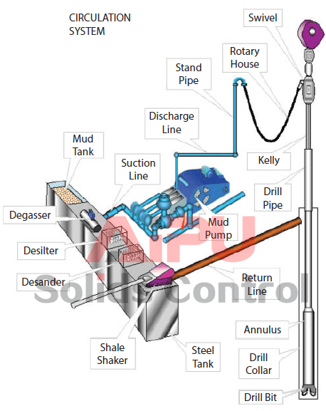
Mud is circulated through a wellbore to bring the cuttings to the surface. Here cuttings are separated out so that clean mud can be reinserted into the well.
A typical circulation system is presented in Figure 1 as an example from a fixed drilling platform, while Figure 2 presents the circulation system from another view; on a floating drilling unit. Here mud is mixed and prepared in the mud pits consisting of several large tanks, each typically 60 m³ large. One or two of the mud tanks are in active use for mud circulation, while the others are for transfer and storing. One reserve pit is for kill mud, where density is kept typically at 0.25 kg/l above the density in the active pits.
Both density and rheology are maintained in the active mud pits. Typical total volume of a mud pit is 200 m³, with a surface area of typically 50 m². A vertical height of two cm corresponds to a volume of 1000 liters! In the surface mud system in Figure 1, we see two pumps in parallel. On offshore rigs it is more common with three.
From the pumps, a high-pressure output line leads up to the drill floor, where, on the standpipe, a multy purpose junction is made, called the standpipe manifold. Here the driller can read the standpipe pressure, which as almost identical with the pump pressure, reduced only by pipe friction in the short distance between the pump and the standpipe manifold.
On its return to the surface, the mud is directed through a wide settling tank, where the largest particles are allowed to settle out: On other rigs this tank is called the sand trap, positioned in front of the shale shakers as an over flow tank.
Low gravity solids (LGS) enter the mud through dispersed or disintegrated cuttings and has a density of 1.8–2.8 kg/l. If its content (LGSC) is increasing above a certain limit, solids control must be intensified.
Pumping drilling fluids through kilometre long pipe systems will result in large hydraulic friction, and correspondingly powerful mud pumps are required. One typical pump is shown in Figure 4.
The mud pump characteristics are divided into two different operating ranges: Range 1 is defined through the pump’s smallest liner, and range 2 includes the rest of the liners. Table 3 presents a typical pump characteristic for large sized mud pumps.

The 2,200-hp mud pump for offshore applications is a single-acting reciprocating triplex mud pump designed for high fluid flow rates, even at low operating speeds, and with a long stroke design. These features reduce the number of load reversals in critical components and increase the life of fluid end parts.
The pump’s critical components are strategically placed to make maintenance and inspection far easier and safer. The two-piece, quick-release piston rod lets you remove the piston without disturbing the liner, minimizing downtime when you’re replacing fluid parts.

The 400T hydrostatic press and 300T mechanical press can be used to support experiments requiring large mechanical force or loads, for example mimicking formation load, placement forces or hydrostatic load. Downhole conditions can be simulated by adding heaters to the components. The presses are characterized by a simple setup to apply force on tools and materials, e.g. to test mechanical loading of casing materials. The 400T setup is able to test larger samples. Samples are automatically handled to ensure safe (hands off) installation of materials, casings, tools etc. Fluids (mud) can also be taken into account for testing. The press is simple to handle, which makes it perfect for quick preparation tests.
The equipment present here enables the researcher to simulate the conditions for drilling in the subsurface. This mainly concerns the simulation of the high pressure that prevails in the subsurface. A drill bit is placed in the pressure vessel that can drill a rock sample that is placed in the pressure bombe. This vessel is connected to the mud pumps in the basement which deliver the fluid pressure for the drilling experiments. The mud with cuttings are transported to the shaker, similar to the ones operated in the field, where the cuttings and the liquid are separated 9similar to field operations). During drilling, a vertical load is applied to the drill head, which can reach up to 50 tons (hence the name). Because these are high pressure experiments, there are high safety standards when performing the experiments. For example, the operator space is protected with extremely thick safety glass. The RCSG uses rock samples from stock or has samples made from cement that can be used for the drilling experiments.
At the RCSG we have large scale flow loops to support research aiming at flow optimization for production and drilling. For the geothermal and district heat sector it is essential to reduce the pump energy for circulation as much as possible. RCSG is supporting a consortium of partners from the district heat sector and academia to investigate environmental friendly drag reducing molecules in the DRAGLOW project. Progress and results of the first phase are shared on the 14th of April 2022, please see more details here.
Cutting flowloop.This flow loop has been developed to investigate the behavior of “cuttings”, the rock and sediments that are released during drilling as grains or small chips. These cuttings need to be removed from the hole in order to prevent the well from clogging up during drilling. This hole cleaning is generally performed by pumping fluid in the well that transports the cuttings to surface. This is a crucial part of the drilling process and can be particularly cumbersome in horizontal wells. The installed tube on the flow loop is transparent, which makes it possible to monitor the flow and transport behavior with cameras. With the tube, which can be arranged horizontally, vertically from an angle, a casing bore is simulated during drilling or production. For example, a rotating drill string can be installed in the pipe to facilitate the situation in the field. It is important to understand the behavior of the cuttings and fines because they can have an impact on the mechanical performance of the drill string and bit and can also have a detrimental effect by wear on the well materials.
ESP flowloop.Geothermal wells in the Netherlands use downhole pumps (Electrical Submersible Pumps) to produce the hot water from the wells. A dedicated set-up is currently being build at RCSG for use on the cutting flowloop frame that enables the investigation of the performance of these ESP’s, as this is critical for the success of geothermal projects.
Narrow annuli flowloop. It is expected that more and more geothermal wells will be drilled with one or more horizontal legs. Wells with horizontal legs are able to deliver more water to a particular geothermal installation at one surface location. This potential increase of power output per surface location will become essential for the built environment where surface area for developemnt of infrastructure is scarce. The horizontal flow loop helps to identify the ideal conditions for cuttings transport from horizontal wells and therefore for the execution of horizontal wells.
Multiphase flow loop.The Multiphase Flow Loop was originally designed and installed to investigate the behavior of mixtures of water, oil and gas. Storage vessels are in place where the liquids can be stored, after which they are mixed into a stream. The flow behavior can be examined in the loop that has a horizontal section that can also put under an angle. For example, you see a viewing window in which you can monitor with a camera. We are currently investigating whether the loop can be put back into operation, for example to investigate scaling, i.e. the precipitation of minerals from the liquid. This is sometimes an operational problem in geothermal installations. It could also be investigated in the future whether experiments can be performed with CO2 or CO2-rich mixtures, relevant for CO2 storage.

CROSS-REFERENCE TO RELATED APPLICATIONS This application claims priority to Provisional U.S. Application Ser. No. 61/679,748, titled "Differential Pressure (DP/DT) Mud Pulse Telemetry While Pumping" and filed August 05, 2012 by Victor J. Stolpman, which is hereby incorporated herein by reference.
In most drilling operations, a circulation pump circulates fluid through a drill string and out the drill bit into a borehole. This fluid (often called "mud" in the oilfield industry) may include water and/or oil and additional additives that may be inert or chemically reactive with other molecular compositions present within a borehole during drilling operations. There are a multitude of motivations for pumping mud with one example being simply to remove earth materials from the borehole.
In Mud Pulse Telemetry (MPT), a measurement-while-drilling (MWD) service company (e.g. Halliburton"s Sperry Drilling) may install at least one transducer/sensor within the surface rig"s plumbing system. The surface rig"s plumbing system mechanically connects the circulation pump(s) (also known as "mud pumps") with the drill string, which in turns couples with a drill-bit within the borehole. MPT systems employ downhole "pulser" located near the drill bit to transmit a series of modulated pressure waves through the mud column within a drill string to communicate real-time information to the surface transducers/sensors. However, the surface transducers may be unable to acquire the encoded pulse waveforms due to various forms of attenuation and interference. For example, the circulation pump hinders the operation of the MPT system through the introduction of pump noise. One attempted solution employs pump dampeners (sometimes called "de-surgers") to buffer the fluid itself,
Accordingly, there are disclosed in the drawings and detailed description specific embodiments of methods and systems that provide effective pump noise removal, thereby enabling differential pressure mud pulse telemetry while drilling. In the drawings:
The following description relates to a variety of mud pulse telemetry (MPT) method, apparatus and system embodiments that enable Measurement While Drilling (MWD) services with real-time data transfer from sensors in a bottomhole assembly (BHA) to a surface location. This disclosure does focus on the receiver side configurations, but this does not imply that this disclosure is limited to surface systems. One skilled in the art will recognize that non-surface system embodiments are readily derivable from the ensuing description.
Fig. 1 depicts an illustrative Mud Pulse Telemetry (MPT) apparatus embodiment and system embodiment in use at a typical drilling installation while operating a Measurement While Drilling (MWD) service. As illustrated, the typical drilling installation includes a drilling derrick 102 at the surface of the well. The derrick may be transportable and temporarily erected on location. The drilling derrick 102 supports the drill string 104 and BHA 106 via a hoist 108 and swivel 110. In the Fig.1 example, the BHA 106 includes a pulser 112, a tool sensor 114, and a drill bit 116. The BHA may further include additional MWD tools, stabilizers, and/or drill collars or heavyweight drill pipe (HWDP) to stiffen the BHA and add additional weight to aid with keeping the drill bit "on-bottom".
The hoist 108 lowers drill string 104 through the rotary table 118 into the casing 120 and beyond into the open borehole 122 until the bit 116 reaches the bottom. The rotary table 118 turns the drill string 104 and bit 116 to extend the borehole through earth formations. If desired, a downhole mud motor can be employed to rotate the bit at a different rate than the drill string.
Circulation pumps 124 take drilling fluid ("mud") from a retention pit 125 and circulate it through a feed pipe 126 to swivel 110 where it flows downward through the drill string interior as indicated by arrow 128. Once the fluid reaches the bit 116, it exits through ports near the cutting elements to entrain and transport rock cuttings upward along the
annulus as indicated by arrow 130. The fluid transports the cuttings into the retention pit 125 via return pipe 132. As the drilling mud circulates through the drill bit, the drilling fluids function additionally as a bit coolant and lubrication extending the lifespan of the bit. Ideally, the weight and hydraulic pressure of the drilling fluid flow balances with the formation pressure to minimize fluid loss to the formation while still preventing an uncontrolled release of formation gases and fluids into the borehole, i.e. a "blowout."
Pumps 124 are normally piston-based, causing a significant degree of pressure variation due to the action of the pistons and valves. A pulsation dampener 134 is positioned along the feed pipe 126 to attenuate the (relatively) high-frequency variation, typically with only a moderate degree of success. Downstream of the pulsation dampener, Fig. 1 shows multiple transducers 136 that respond to pressure variation of fluid in the feed pipe 126. The transducers 136 can be directly coupled to the fluid to physically respond to pressure variations, or coupled to a tubular housing the fluid flow to measure dimensional changes resulting from pressure variation in the flow stream. The transducer provides a measurable reference signal (e.g. voltage, current, phase, position, etc.) sensitive to the temporal derivative of pressure, i.e. dP(t)/dt, with a response that is proportional to within an understood distortion (e.g., scalar gain, constant phase shift, time-shift, finite precision, etc.).
A transducer interface 138 converts the transducer response into an electrical signal suitable for digitization and processing by system 140. System 140 may be dedicated MPT receiver electronics or a general purpose computer with a data acquisition card and suitable software for processing the acquired transducer signal(s). Among other things, system 140 may include circuitry, firmware, or software that implements a pump noise filter that produces a receive signal having a reduced pump noise component.
To communicate with the surface, a downhole "pulser" induces pressure fluctuations in the flow stream 128. The pressure fluctuations propagate upstream as pressure waves 142
until they reach the transducers 136. Information can be encoded into the pressure waves via modulation such as frequency modulation, phase modulation, pulse position modulation, and pulse width modulation. Other suitable modulation schemes also exist. The chosen modulation scheme preferably provides sufficient detection signal-to-noise ratio despite the attenuation, dispersion, and noise effects introduced into the flow stream 128.
As part of the BHA 106, the down-hole pulser 112 may be mechanically and/or electrically coupled with additional down-hole sensors 114 that measure, calculate and/or sense various conditions within or near the bottom of the borehole being drilled. The BHA may have an electrical power source and inter-communicating control buses that facilitate the transfer of data between BHA components. Not limited to the following, the electrical power source may be batteries and/or generator-based deriving power from the flow of fluids via turbine or like mechanism. Likewise, not limited to the following, said control bus lines may be of a metallic, conductive material for use with electrical systems and/or dielectric material when used with optical sources. Fig.1 illustrates a single downhole tool sensor coupled with a pulser, but those skilled in the art understand MWD BHA configurations may have a multitude of tools above and/or below a pulser and may utilize more than one communication media, e.g. mud pulse and electromagnetic telemetry.
The pulser 112 actuates a valve at least in part to encoding the measurement data stream as pressure modulations of the flow stream. Fig. 2A shows a first illustrative pulser implementation having a valve or variable flow restrictor formed from a circular, fan-like stator 201 having multiple fan blades/fins extending radially from a central hub, and a similarly shaped rotor 202 that can oscillate with respect to the (stationary) stator 201. In this implementation, the valve is said to be closed when the relative alignment of the stator and rotor fins maximally restricts fluid flow (by misaligning the openings between blades). It is said to be open when the relative alignment of the stator and rotor fins minimally restricts fluid flow (by aligning the openings between blades).
The valve is coupled serially within the fluid column to restrict (when closed) or ease (when open) the flow of fluid through the valve towards the drill-bit. When the valve is closed, a pressure build up occurs within the fluid on the source side creating a positive pressure change that propagates up to the surface. A subsequent opening of the valve enables the upstream pressure to drop to its previous pressure. Thus as the rotor 202 oscillates, the valve creates a periodic pressure pulsation that is amenable to frequency and phase modulation.
Fig. 2C shows a third illustrative pulser implementation having a flow orifice 206 and a poppet 208 that moves relative to the orifice to restrict (when closed) and ease (when opened) the flow of fluid through the valve. A closing and re-opening of the valve (also referred to as a momentary closing of the valve) generates an upgoing pressure pulse
Fig. 2D shows a fourth illustrative pulser implementation, which is often termed a "negative pulser". This pulser configuration includes a bypass valve to vent fluid from the drill string bore into the annulus, thereby bypassing the drill bit. This venting of drilling fluid produces a pressure drop (i.e. a negative pressure change) within the drill string"s fluid column. Fig. 2D shows a valve seat and gate 210 configuration. The gate 210 moves relative to the seat to close the valve (i.e., restrict fluid flow into the annulus) and open the valve (permit fluid flow into the annulus). After closing the valve, the fluid pressure immediately rises in the drill-string column towards the steady- state pressure prior to the valve"s opening of the valve. As the name suggests, this opening and closing actuation of the valve creates a negative pulse that propagates throughout the column of drilling fluid.
Conventional strain gauge sensors may serve as transducers 136 to provide a measurable reference, e.g. 4-20mA current, proportional to the mechanical fluid pressure present at the coupling point, i.e. P(t), by being directly coupled to the drilling fluid flow. Alternatively, such strain gauges could be employed to measure the strains that the rig"s plumbing undergoes when a mud pulse is present and/or absent. Examples of manufacturers of said sensors include but not limited to Honeywell and Rosemount (Emerson Electric affiliated).
commensurate strain in the plumbing that is proportional to the pressure signal derivative. For the former measurement, direct coupling of the transducer to the fluid flow can be used. For the latter, the transducer can be coupled to the surface of a tubular in the drill rig"s plumbing (e.g., feed pipe 126). In the illustrated embodiment, transducers 136 each include an optical fiber winding on the feed pipe to measure the strains via small changes in the feed pipe dimensions.
Despite the presence of pulsation dampener 134, the measurements of transducers 136 include a significant pump noise component. Accordingly, system 140 includes a pump filter that targets the cyclostationary noise generated by the pump strokes. Fig. 3 A shows an illustrative pressure variation P(t) that might be present within a feed pipe fluid flow carrying a mud pulse telemetry signal. Fig. 3B shows an illustrative pump noise component of this pressure variation. Notably, this pump noise component is the primary source of pressure variation, but it has a regular cyclostationary character that enables accurate estimation. Fig. 3C shows the difference between the illustrative pressure variation and the illustrative pump noise component. The pressure variation in this illustrative difference is primarily the mud pulse telemetry signal.
Various embodiments of a pump filter may utilize memory storage for holding estimates of "pump signatures". A pump signature estimator may extract such pump signatures from transducer measurements (including transducers responsive to the temporal derivative of pressure, dP(t)/dt ) of the drilling fluid flowing through the tubular at each location where the transducers are coupled with the rig"s plumbing. A pump stroke position monitor (e.g., a whisker switch whose state is coupled to the pump piston"s position) may be included in system 140 and used by the pump signature estimator and the pump filter module to assist with noise removal. The pump signature expectedly includes acoustic distortions of pump noise observable at the transducer locations, including channel effects such as
attenuation, dispersion, and acoustic reflections. In some embodiments, the pump filter module obtains a negated pump signature from the estimator and adds it to the receive signal. The pump signature can be stored in derivative form or regular pressure domain form. The system 140 may employ a processor to identify pump filter parameters and maintain said pump signatures. The system 140 then relies on the pump signatures to filter and remove at least a portion of the cyclostationary pump noise, thereby yielding at the pump filter"s output a filtered version of the transducer measurements.
Fig. 4 shows illustrative signals with an expanded time axis. Curve 402 is an illustrative pressure derivative dP(t)/dt signal which, when integrated over time, yields a pressure P(t) curve 404. For comparison, curve 406 is a pressure curve acquired with a strain gauge sensor. However, this disclosure contemplates measurements of any physical phenomenon that reflects the pressure fluctuations of the surface fluid flow.
Fig. 5 shows an illustrative MPT receiver having an analog integrator. Transducer interface 138 is implemented as an interferometer having a light source 502 which transmits at least one spectral frequency or wavelength to a optical splitter 504. Illustrative light source 502 types include a laser diode, a laser, and a light emitting diode. The optical splitter 504 sends light 506 and 508 in opposite directions around a loop formed from a series of optical waveguides. The illustrated loop includes a fiber optic cable 510, a reference (delay) coil, and a transducer 136 coupled to the feed pipe 126. Additional transducers 136 can be employed for redundancy and/or enhanced signal processing (including directional detection). For example, the embodiment of Fig. 1, has three transducers 136 to obtain spaced apart dP(t)/dt measurements. The transducer locations need not be limited to the feed pipe 126, but rather they can be positioned at any suitable location in the rig"s plumbing including the stand pipe, flex hose, return line, or the casing annulus.
possibly mechanically attached or adhered) around the drilling rig"s plumbing with sufficient contact such that changes in the tubular housing due to fluid pressure will change the tension within the fiber optic dielectric. The loop returns the light 514 and 518 to optical splitter 504, which provides a combined beam to light sensor 520. The overall fiber optic loop has a finite path length, say L, and includes a measurement section (i.e. portion of cable wrapped against the conduit housing) of a length less than L, say X where X< L, and delay section also of finite length, say L-X. In one embodiment, the measurement section may be 2-10 meters in length. In this example, the measurement portion is at least partially wrapped against said conduit containing pressurized fluids and encoded pulses. In some embodiments, the delay section is on the order of 500-3000 meters in length.
In the embodiment of Fig. 5, system 140 includes an analog-to-digital converter 526 to digitize the signal from the transducer interface 138. System 140 further includes an processing module 528 for initial filtering of the digital signal stream, e.g., low pass filtering, decimation to a desired sampling rate, etc. A pump filter module 530 removes pump noise from the signal. Modules 532 and 534 perform demodulation and decoding to extract the telemetry data stream from the filtered signal. In at least some system embodiments, these modules can be combined to enable so-called "soft" decoding. A data module 536 performs de-framing and demultiplexing to separate the data stream into log data for the corresponding sensors. Log module 538 performs tool-specific processing of the log data to derive the tool logs as a function of tool position. A display module 540 presents the tool logs as a printed or displayed image or in some other non-transient, tangible form such as database system that stores data and makes it available as needed in formatted reports and log plots. System 140 may include a graphical user interface (GUI) or may be coupled to a computer or computer
For example, Fig. 6 shows an alternative MPT receiver having a digital integrator 550 rather than the analog integrator 524 of Fig. 5. In Fig. 6, the digital integrator 550 is positioned between the pump filter 530 and detector module 532, but it could equally well be positioned before the pump filter 530 or even before the processor module 528. Alternatively, digital integrator 550 could be combined with one of these other modules. In the illustrated configuration, pump filter 530 is able to operate solely with pump signatures in the derivative domain (dP/dt) rather than in the pressure domain P(t). There may be certain competitive advantages created by the use of a pump filter with at least one surface dP/dt sensor, and certainly by the use of transducers that do not require direct access to the fluid flow or cutting of the rig plumbing. Such non-invasive transducers further facilitate the placement of multiple transducers to enable array filtering and signal-to-noise ratio improvement through the use of multiple independent sensors having spatial diversity.
Some alternative embodiments may further include at least one additional pump filter for removing residual pump noise. In some cases, the additional pump noise filter operates on the derivative signal dP/dt, whereas in others the additional pump noise filtering occurs after an integration of dP/dt signals.
measurements from one or more downhole sensors 114, and through the use of dedicated circuitry 704 or a programmable processor 706 coupled to memory 708 to execute suitable encoding software, converts the measurements to a modulated data stream 710. A pulser 112 transmits the modulated data stream as a series of pressure variations 142 to the surface. With one or more transducers, the pressure variations 142 are converted by transducer interface(s) 138 to derivative pressure signals dP/dt. An analog integrator 524 integrates the derivative signal to provide processor module 528 with a pressure signal P(t). A pump filter module 530 removes at least some of the pump noise, and decoder module 534 converts the signal into a received data stream. Data module 536 demultiplexes the data stream into log data for the individual sensors, and logging module 538 performs tool-specific processing of the log data. A user interface 720 controls the demultiplexing process and enables viewing and processing of the log data.
Fig. 8 is distinguished from Fig. 7 by the omission of analog integrator 524 and the insertion of digital integrator 550 after the pump filter 530. As before, this placement of the digital integrator enables pump noise filtering to be performed on the pressure derivative signal.
In terms of method embodiments, at least some of the disclosed MPT systems sense pressure, strain, and/or some other physical phenomenon indicative of the time derivative of pressure fluctuation in a drilling fluid flow to within an understood distortion. The sensing may occur at one or more points in the drilling rig"s surface plumbing, such as a feed pipe downstream of a pulsation dampener. The sensed derivative is processed to remove at least some of a pump noise component before being demodulated and decoded to extract the telemetry data stream. At least some of the disclosed system embodiments include analog or digital integration to convert the derivative signal into a pressure signal. As part of the demodulation and decoding process, some system embodiments may include equalizers,
pulse detectors, edge detectors, and/or timing modules to decode the receive signal. Some system configurations may employ array processing of the signals as part of the pump noise removal and/or the equalization process. As part of the pump noise removal, some system embodiments estimate the pressure derivative pump signatures with a training or adaptive filtering process, store the signatures in memory, and subtract the signatures from the corresponding transducer signal. The signature estimation and removal operations may include a phase lock loop to track a fundamental frequency or period of the pump noise and a current phase. At least some disclosed embodiments may additionally or alternatively sense a pump stroke position with a sensor affixed to the pump.
At least some of the disclosed MPT system embodiments perform pump noise filtering in stages, with a first pump noise filter removing some of the pump noise prior to integration, and a second pump noise filter removing residual pump noise after integration. Each pump noise filter may include modules for estimating a pump noise signature at that stage of processing.
Numerous modifications, equivalents, and alternatives will become apparent to those skilled in the art once the above disclosure is fully appreciated. For example, the foregoing description focuses on uplink communication from the BHA to the surface, but this disclosure also applies to downlink communication from the surface to the BHA, with the noise filters being employed to remove cyclostationary noise from downhole noise sources such as the bit, mud motor, rotary steerable device, and/or friction between the BHA and the
There are many different ways to drill a domestic water well. One is what we call the “mud rotary” method. Whether or not this is the desired and/or best method for drilling your well is something more fully explained in this brief summary.
One advantage of drilling with compressed air is that it can tell you when you have encountered groundwater and gives you an indication how much water the borehole is producing. When drilling with water using the mud rotary method, the driller must rely on his interpretation of the borehole cuttings and any changes he can observe in the recirculating fluid. Mud rotary drillers can also use borehole geophysical tools to interpret which zones might be productive enough for your water well.
The mud rotary well drilling method is considered a closed-loop system. That is, the mud is cleaned of its cuttings and then is recirculated back down the borehole. Referring to this drilling method as “mud” is a misnomer, but it is one that has stuck with the industry for many years and most people understand what the term actually means.
The water is carefully mixed with a product that should not be called mud because it is a highly refined and formulated clay product—bentonite. It is added, mixed, and carefully monitored throughout the well drilling process.
The purpose of using a bentonite additive to the water is to form a thin film on the walls of the borehole to seal it and prevent water losses while drilling. This film also helps support the borehole wall from sluffing or caving in because of the hydraulic pressure of the bentonite mixture pressing against it. The objective of the fluid mixture is to carry cuttings from the bottom of the borehole up to the surface, where they drop out or are filtered out of the fluid, so it can be pumped back down the borehole again.
When using the mud rotary method, the driller must have a sump, a tank, or a small pond to hold a few thousand gallons of recirculating fluid. If they can’t dig sumps or small ponds, they must have a mud processing piece of equipment that mechanically screens and removes the sands and gravels from the mixture. This device is called a “shale shaker.”
The driller does not want to pump fine sand through the pump and back down the borehole. To avoid that, the shale shaker uses vibrating screens of various sizes and desanding cones to drop the sand out of the fluid as it flows through the shaker—so that the fluid can be used again.
Some drillers use compressed air to blow off the well, starting at the first screened interval and slowly working their way to the bottom—blowing off all the water standing above the drill pipe and allowing it to recover, and repeating this until the water blown from the well is free of sand and relatively clean. If after repeated cycles of airlift pumping and recovery the driller cannot find any sand in the water, it is time to install a well development pump.
Additional development of the well can be done with a development pump that may be of a higher capacity than what the final installation pump will be. Just as with cycles of airlift pumping of the well, the development pump will be cycled at different flow rates until the maximum capacity of the well can be determined. If the development pump can be operated briefly at a flow rate 50% greater than the permanent pump, the well should not pump sand.
Mud rotary well drillers for decades have found ways to make this particular system work to drill and construct domestic water wells. In some areas, it’s the ideal method to use because of the geologic formations there, while other areas of the country favor air rotary methods.
To learn more about the difference between mud rotary drilling and air rotary drilling, click the video below. The video is part of our “NGWA: Industry Connected” YouTube series:


 8613371530291