
mud pump flow rate free sample

I’ve run into several instances of insufficient suction stabilization on rigs where a “standpipe” is installed off the suction manifold. The thought behind this design was to create a gas-over-fluid column for the reciprocating pump and eliminate cavitation.
When the standpipe is installed on the suction manifold’s deadhead side, there’s little opportunity to get fluid into all the cylinders to prevent cavitation. Also, the reciprocating pump and charge pump are not isolated.
The suction stabilizer’s compressible feature is designed to absorb the negative energies and promote smooth fluid flow. As a result, pump isolation is achieved between the charge pump and the reciprocating pump.
The isolation eliminates pump chatter, and because the reciprocating pump’s negative energies never reach the charge pump, the pump’s expendable life is extended.
Investing in suction stabilizers will ensure your pumps operate consistently and efficiently. They can also prevent most challenges related to pressure surges or pulsations in the most difficult piping environments.

Rig pump output, normally in volume per stroke, of mud pumps on the rig is one of important figures that we really need to know because we will use pump out put figures to calculate many parameters such as bottom up strokes, wash out depth, tracking drilling fluid, etc. In this post, you will learn how to calculate pump out put for triplex pump and duplex pump in bothOilfield and Metric Unit.
Pumps are an integral part of almost all industries today. From construction and mining to automotive and aerospace, pumps play a vital role in keeping these industries moving forward. While there are many essential parameters in pumps, one critical parameter is the pump flow rate which becomes a guiding factor for pump manufacturers.
The pump flow rate is one of the most important factors to consider when selecting a pump. It measures how much water the pump can move in a given period of time and is typically expressed in cubic meters/hour (m3/ h). If you’re looking for a pump to use in your home or business, it’s essential to know the flow rate needed to meet your needs. Otherwise, you may end up with a pump that isn’t powerful enough or one that uses more energy than necessary.
The first step is to determine what your needs are. For example, if you’re using the pump to provide water for irrigation, you’ll need to know the maximum flow rate that will be required. Once you know your needs, you can start looking for pumps that have the required flow rate, as you will now be able to give more precise directions to the pump manufacturers about your requirement.
To choose the right pump, it’s also important to consider other factors, such as pump size and efficiency. For instance, a large pump with a high flow rate may be more expensive to purchase and operate than a smaller pump with a lower flow rate. However, it may still be the better option if your water usage is consistently high or you have multiple zones in your irrigation system that need water simultaneously.
Overall, choosing the right pump for your home or business requires careful consideration of all aspects of pumping performance. With the right pump from reliable pump manufacturers, you can rest assured that you’ll always have an adequate supply of water on demand.
Pump flow rate simply refers to the volume of fluid that is moving through a pump in a given time period. There are various units through which it is measured, and they include cubic meter/hour (m3/h), litre/sec (l/s) or gallons per minute (GPM). Different pump manufacturers refer to different pump flow units.
The flow rate of a pump can be affected by several factors, including the size and type of pump, the speed at which it is operating, and the resistance of the system it is pumping into.
Pump Speed: This is the number of times the pump can complete an entire cycle in a minute and is measured in rotations per minute (rpm). The faster the pump speed, the higher the flow rate.
Pump Size: Larger pumps can move more liquid than smaller pumps. This is why it’s essential to choose an appropriately sized pump for your application.
Liquid Density: Heavier liquids (such as oil) will flow more slowly than lighter liquids (such as water). This is because it takes more energy to move a heavier liquid.
Liquid Viscosity: Viscous liquids (such as honey) will flow more slowly than non-viscous liquids (such as water). This is because it takes more energy to move a viscous liquid.
Pipe Size: The larger the pipe diameter, the higher the flow rate. This is because there is less resistance to flow when there is a larger diameter pipe.
Pipe Length: The shorter the length of the pipe, the higher the flow rate. This is because there is less resistance to flow when there is a shorter length of pipe.
Pipe Bends: The fewer the number of bends in the pipe, the higher the flow rate. This is because there is less resistance to flow when there are fewer bends in the pipe.
Now that you know the basics of pump flow rate, you can begin to select a pump that is appropriate for your application. Keep in mind that the factors listed above will all affect pump flow rate, so it’s essential to consider each one when you give your requirements to the pump manufacturers.
Pump speed is measured in revolutions per minute (rpm). To convert from rpm to hertz, divide by 60. For example, if a pump operates at 1000 rpm, its frequency would be 16.67 Hz.
Let’s say you have a pump that is operating at 1000 rpm, has an impeller size of 6 inches, and is pumping water with a density of 62.4 lb/ft3. So the flow rate would be:
The good news is that there are many online flow rate calculators available for free, which you can consider using if you do want to get into too much mathematics.
There are a few key ways to increase the flow rate efficiency in pumps. One is to choose the right pump for the application. Another way is to ensure that the pump is sized correctly for the application. Additionally, regular maintenance can help keep a pump operating at peak efficiency.
When choosing a pump, it is vital to consider the application’s specific needs. For example, if a pump is handling a corrosive fluid, you should select stainless steel or other corrosion-resistant models. Similarly, if the fluid being pumped will be unusually viscous, then a positive displacement pump may be the best option.
Ensuring that a pump is appropriately sized for its application is also critical to maximizing flow rate efficiency. If a pump is too small for the task at hand, it will have to work much harder and will be less efficient. On the other hand, if a pump is too large for the application, it will not operate at peak efficiency.
Finally, regular maintenance is essential to keeping a pump operating at its best. This includes things like inspecting and cleaning the pump regularly and making sure that all of the moving parts are adequately lubricated. By taking these steps, it is possible to keep a pump running at peak efficiency for many years.
Pumps tend to be one of the biggest energy consumers in industrial operations. Pump motors, specifically, require a lot of energy. For instance, a 2500 HP triplex pump used for frac jobs can consume almost 2000 kW of power, meaning a full day of fracking can cost several thousand dollars in energy costs alone!
So, naturally, operators should want to maximize energy efficiency to get the most for their money. Even a 1% improvement in efficiency can decrease annual pumping costs by tens of thousands of dollars. The payoff is worth the effort. And if you want to remotely control your pumps, you want to keep efficiency in mind.
In this post, we’ll point you in the right direction and discuss all things related to pump efficiency. We’ll conclude with several tips for how you can maintain pumping efficiency and keep your energy costs down as much as possible.
In simple terms, pump efficiency refers to the ratio of power out to power in. It’s the mechanical power input at the pump shaft, measured in horsepower (HP), compared to the hydraulic power of the liquid output, also measured in HP. For instance, if a pump requires 1000 HP to operate and produces 800 HP of hydraulic power, it would have an efficiency of 80%.
Remember: pumps have to be driven by something, i.e., an electric or diesel motor. True pump system efficiency needs to factor in the efficiency of both the motor AND the pump.
Consequently, we need to think about how electrical power (when using electric motors) or heat power (when using combustion engines) converts into liquid power to really understand pump efficiency.
Good pump efficiency depends, of course, on pump type and size. High-quality pumps that are well-maintained can achieve efficiencies of 90% or higher, while smaller pumps tend to be less efficient. In general, if you take good care of your pumps, you should be able to achieve 70-90% pump efficiency.
Now that we have a better understanding of the pump efficiency metric, let’s talk about how to calculate it. The mechanical power of the pump, or the input power, is a property of the pump itself and will be documented during the pump setup. The output power, or hydraulic power, is calculated as the liquid flow rate multiplied by the "total head" of the system.
IMPORTANT: to calculate true head, you also need to factor in the work the pump does to move fluid from the source. For example, if the source water is below the pump, you need to account for the extra work the pump puts in to draw source water upwards.
*Note - this calculation assumes the pump inlet is not pressurized and that friction losses are minimal. If the pump experiences a non-zero suction pressure, or if there is significant friction caused by the distance or material of the pipe, these should be factored in as well.
You"ll notice that the elevation head is minimal compared to the discharge pressure, and has minimal effect on the efficiency of the pump. As the elevation change increases or the discharge pressure decreases, however, elevation change will have a greater impact on total head.
Obviously, that’s a fair amount of math to get at the pump efficiency, considering all of the units conversions that need to be done. To avoid doing these calculations manually, feel free to use our simple pump efficiency calculator.
Our calculations use static variables (pump-rated horsepower and water source elevation) and dynamic variables (discharge flow and pressure). To determine pump efficiency, we need to measure the static variables only once, unless they change.
If you want to measure the true efficiency of your pump, taking energy consumption into account, you could add an electrical meter. Your meter should consist of a current transducer and voltage monitor (if using DC) for electrical motors or a fuel gauge for combustion. This would give you a true understanding of how pump efficiency affects energy consumption, and ultimately your bank account.
Up until this point, we’ve covered the ins and outs of how to determine pump efficiency. We’re now ready for the exciting stuff - how to improve pump efficiency!
One of the easiest ways to improve pump efficiency is to actually monitor pumps for signs of efficiency loss! If you monitor flow rate and discharge (output power) along with motor current or fuel consumption, you’ll notice efficiency losses as soon as they occur. Simply having pump efficiency information on hand empowers you to take action.
Another way to increase efficiency is to keep pumps well-maintained. Efficiency losses mostly come from mechanical defects in pumps, e.g., friction, leakages, and component failures. You can mitigate these issues through regular maintenance that keeps parts in working order and reveals impending failures. Of course, if you are continuously monitoring your pumps for efficiency drops, you’ll know exactly when maintenance is due.
You can also improve pump efficiency by keeping pumps lubricated at all times. Lubrication is the enemy of friction, which is the enemy of efficiency (“the enemy of my enemy is my friend…”).
A fourth way to enhance pump efficiency is to ensure your pumps and piping are sized properly for your infrastructure. Although we’re bringing this up last, it’s really the first step in any pumping operation. If your pumps and piping don’t match, no amount of lubricant or maintenance will help.
In this post, we’ve given you the full rundown when it comes to calculating and improving pump efficiency. You can now calculate, measure, and improve pump efficiency, potentially saving your business thousands of dollars annually on energy costs.
For those just getting started with pump optimization, we offer purpose-built, prepackaged solutions that will have you monitoring pump efficiency in minutes, even in hazardous environments.
When choosing a size and type of mud pump for your drilling project, there are several factors to consider. These would include not only cost and size of pump that best fits your drilling rig, but also the diameter, depth and hole conditions you are drilling through. I know that this sounds like a lot to consider, but if you are set up the right way before the job starts, you will thank me later.
Recommended practice is to maintain a minimum of 100 to 150 feet per minute of uphole velocity for drill cuttings. Larger diameter wells for irrigation, agriculture or municipalities may violate this rule, because it may not be economically feasible to pump this much mud for the job. Uphole velocity is determined by the flow rate of the mud system, diameter of the borehole and the diameter of the drill pipe. There are many tools, including handbooks, rule of thumb, slide rule calculators and now apps on your handheld device, to calculate velocity. It is always good to remember the time it takes to get the cuttings off the bottom of the well. If you are drilling at 200 feet, then a 100-foot-per-minute velocity means that it would take two minutes to get the cuttings out of the hole. This is always a good reminder of what you are drilling through and how long ago it was that you drilled it. Ground conditions and rock formations are ever changing as you go deeper. Wouldn’t it be nice if they all remained the same?
Centrifugal-style mud pumps are very popular in our industry due to their size and weight, as well as flow rate capacity for an affordable price. There are many models and brands out there, and most of them are very good value. How does a centrifugal mud pump work? The rotation of the impeller accelerates the fluid into the volute or diffuser chamber. The added energy from the acceleration increases the velocity and pressure of the fluid. These pumps are known to be very inefficient. This means that it takes more energy to increase the flow and pressure of the fluid when compared to a piston-style pump. However, you have a significant advantage in flow rates from a centrifugal pump versus a piston pump. If you are drilling deeper wells with heavier cuttings, you will be forced at some point to use a piston-style mud pump. They have much higher efficiencies in transferring the input energy into flow and pressure, therefore resulting in much higher pressure capabilities.
Piston-style mud pumps utilize a piston or plunger that travels back and forth in a chamber known as a cylinder. These pumps are also called “positive displacement” pumps because they literally push the fluid forward. This fluid builds up pressure and forces a spring-loaded valve to open and allow the fluid to escape into the discharge piping of the pump and then down the borehole. Since the expansion process is much smaller (almost insignificant) compared to a centrifugal pump, there is much lower energy loss. Plunger-style pumps can develop upwards of 15,000 psi for well treatments and hydraulic fracturing. Centrifugal pumps, in comparison, usually operate below 300 psi. If you are comparing most drilling pumps, centrifugal pumps operate from 60 to 125 psi and piston pumps operate around 150 to 300 psi. There are many exceptions and special applications for drilling, but these numbers should cover 80 percent of all equipment operating out there.
The restriction of putting a piston-style mud pump onto drilling rigs has always been the physical size and weight to provide adequate flow and pressure to your drilling fluid. Because of this, the industry needed a new solution to this age-old issue.
As the senior design engineer for Ingersoll-Rand’s Deephole Drilling Business Unit, I had the distinct pleasure of working with him and incorporating his Centerline Mud Pump into our drilling rig platforms.
In the late ’90s — and perhaps even earlier — Ingersoll-Rand had tried several times to develop a hydraulic-driven mud pump that would last an acceptable life- and duty-cycle for a well drilling contractor. With all of our resources and design wisdom, we were unable to solve this problem. Not only did Miller provide a solution, thus saving the size and weight of a typical gear-driven mud pump, he also provided a new offering — a mono-cylinder mud pump. This double-acting piston pump provided as much mud flow and pressure as a standard 5 X 6 duplex pump with incredible size and weight savings.
The true innovation was providing the well driller a solution for their mud pump requirements that was the right size and weight to integrate into both existing and new drilling rigs. Regardless of drill rig manufacturer and hydraulic system design, Centerline has provided a mud pump integration on hundreds of customer’s drilling rigs. Both mono-cylinder and duplex-cylinder pumps can fit nicely on the deck, across the frame or even be configured for under-deck mounting. This would not be possible with conventional mud pump designs.
The second generation design for the Centerline Mud Pump is expected later this year, and I believe it will be a true game changer for this industry. It also will open up the application to many other industries that require a heavier-duty cycle for a piston pump application.

This rig features a Mission 4-by-5 centrifugal pump. Courtesy of Higgins Rig Co.Returning to the water well industry when I joined Schramm Inc. last year, I knew that expanding my mud pump knowledge was necessary to represent the company"s mud rotary drill line properly. One item new to me was the centrifugal mud pump. What was this pump that a number of drillers were using? I had been trained that a piston pump was the only pump of any ability.
As I traveled and questioned drillers, I found that opinions of the centrifugal pumps varied. "Best pump ever built," "What a piece of junk" and "Can"t drill more than 200 feet with a centrifugal" were typical of varying responses. Because different opinions had confused the issue, I concluded my discussions and restarted my education with a call to a centrifugal pump manufacturer. After that conversation, I went back to the field to continue my investigation.
For the past eight months, I have held many discussions and conducted field visits to understand the centrifugal pump. As a result, my factual investigation has clearly proved that the centrifugal pump has a place in mud rotary drilling. The fact also is clear that many drilling contractors do not understand the correct operational use of the pump. Following are the results of my work in the field.
High up-hole velocity - High pump flow (gpm) moves cuttings fast. This works well with lower viscosity muds - reducing mud expense, mixing time and creating shorter settling times.
Able to run a desander - The centrifugal"s high volume enables a desander to be operated off the pump discharge while drilling without adding a dedicated desander pump.
6. Sticky clays will stall a centrifugal pump"s flow. Be prepared to reduce your bit load in these conditions and increase your rpm if conditions allow. Yes, clays can be drilled with a centrifugal pump.
7. Centrifugal pumps cannot pump muds over 9.5 lbs./gal. Centrifugal pumps work best with a 9.0 lbs./gal. mud weight or less. High flow rate move cuttings, not heavy mud.
The goal of this article has been to increase awareness of the value of the centrifugal pump and its growing use. Although the centrifugal pump is not flawless, once its different operating techniques are understood, drilling programs are being enhanced with the use of this pump.
If you wish to learn more, please talk directly to centrifugal pump users. Feel free to call me at 314-909-8077 for a centrifugal pump user list. These drillers will gladly share their centrifugal pump experiences.
Kverneland, Hege, Kyllingstad, Åge, and Magne Moe. "Development and Performance Testing of the Hex Mud Pump." Paper presented at the SPE/IADC Drilling Conference, Amsterdam, Netherlands, February 2003. doi: https://doi.org/10.2118/79831-MS

Wells are generally drilled into the ground to recover natural deposits of hydrocarbons and other desirable materials trapped in geological formations in the Earth"s crust. A well is typically drilled using a drill bit attached to the lower end of a drill string. The well is drilled so that it penetrates the subsurface formations containing the trapped materials and the materials can be recovered.
The drilling operations are controlled by an operator at the surface. The drill string is rotated at a desired rate by a rotary table, or top drive, at the surface, and the operator controls the weight-on-bit and other operating parameters of the drilling process.
Another aspect of drilling and well control relates to the drilling fluid, called "mud." The mud is a fluid that is pumped from the surface to the drill bit by way of the drill string. The mud serves to cool and lubricate the drill bit, and it carries the drill cuttings back to the surface. The density of the mud is carefully controlled to maintain the hydrostatic pressure in the borehole at desired levels.
One common method of communication is called "mud pulse telemetry." Mud pulse telemetry is a method of sending signals, either downlinks or unlinks, by creating pressure and/or flow rate pulses in the mud. These pulses may be detected by sensors at the receiving location. For example, in a downlink operation, a change in the pressure or the flow rate of the mud being pumped down the drill string may be detected by a sensor in the BHA. The pattern of the pulses, such as the frequency and the amplitude, may be detected by the sensors and interpreted so that the command may be understood by the BHA.
Mud pulse telemetry is well known in the drilling art. A common prior art technique for downlinking includes the temporary interruption of drilling operations so that the mud pumps at the surface can be cycled on and off to create the pulses. Drilling operations must be interrupted because the drill bit requires a continuous flow of mud to operate properly. Thus, drilling must be stopped while the mud pumps are being cycled.
Figure IA shows a prior art mud pulse telemetry system 100. The system 100 includes a mud pump 102 that pumps the mud from the surface, to the BHA 112, and back to the surface. A typical drilling rig will have multiple mud pumps that cooperate to pump the mud. Mud pumps are positive displacement pumps, which are able to pump at a constant flow rate at any pressure. These pumps are diagrammatically represented as one pump 102.
Mud from the mud storage tank 104 is pumped through the pump 102, into a standpipe 108, and down the drill string 110 to the drill bit 114 at the bottom of the BHA l 12. The mud leaves the drill string 1 10 through ports (not shown) in the drill bit 114, where it cools and lubricates the drill bit 114. The mud also carries the drill cuttings back to the surface as it flows up through the annulus 1 16. Once at the surface, the mud flows through a mud return line 118 that returns the mud to the mud storage tank 104. A downlink operation involves cycling the pump 102 on and off to create pulses in the mud. Sensors in the BHA detect the pulses and interpret them as an instruction.
Another prior art downlink technique is shown in Figure 1B. The downlink signal system 120 is a bypass from the standpipe 108 to the mud return line 118. The system 120 operates by allowing some of the mud to bypass the drilling system. Instead of passing through the drill string (110 in Figure IA), the BHA (112 in Figure IA), and returning through the annulus (116 in Figure I A), a relatively small fraction of the mud flowing through the standpipe 108 is allowed to flow directly into the mud return line 118. The mud flow rate to the BHA (not shown) is decreased by the amount that flows through the bypass system 120.
The bypass system 120 includes a choke valve 124. During normal operations, the choke valve 124 may be closed to prevent any flow through the bypass system 120.
The full output of the mud pump 102 will flow to the BHA (not shown) during normal operations. When an operator desires to send an instruction to the BHA (not shown), a downlink signal may be generated by sequentially opening and closing the choke valve 124. The opening and closing of the choke valve 124 creates fluctuations in the mud flow rate to the BHA (not shown) by allowing a fraction of the mud to flow through the bypass 120. These pulses are detected and interpreted by the sensors in the BHA (not shown). The bypass system 120 may include flow restrictors 122, 126 to help regulate the flow rate through the system 120.
One advantage to this type of system is that a bypass system diverts only a fraction of the total flow rate of mud to the BHA. With mud still flowing to the BHA and the drill bit, drilling operations may continue, even while a downlink signal is being sent.
One aspect of the invention relates to a downlink system comprising at least one mud pump for pumping drilling fluid from a drilling fluid storage tank to a drilling system, a standpipe in fluid communication with the mud pump and in fluid communication with the drilling system, a return line in fluid communication with the drilling system for returning the drilling fluid to the drilling fluid storage tank, and a drilling fluid modulator in fluid communication with at least one of the group consisting of the standpipe and the return line.
Another aspect of the invention relates to a method of transmitting a downlink signal comprising pumping drilling fluid to a drilling system and selectively operating a modulator to create pulses in a drilling fluid flow. In some embodiments the modulator is disposed in a standpipe.
Yet another aspect of the invention relates to a drilling fluid pump controller comprising at least one actuation device coupled to a control console, and at least one connector coupled to the at least one actuation device and a pump control mechanism.
A still further aspect of the invention relates to a method for generating a downlink signal comprising coupling an actuation device to a pump control panel, coupling the actuation device to a pump control device on the pump control panel, and creating a pulse in a drilling fluid flow by selectively controlling the pump control device with the actuation device.
Another aspect of the invention relates to a downlink system comprising a drilling fluid pump in fluid communication with a drilling system, the drilling fluid pump having a plurality of pumping elements, and a pump inefficiency controller operatively coupled to at least one of the plurality of pumping elements for selectively reducing the efficiency of the at least one of the plurality of pumping elements.
Another aspect of the invention relates to a method of generating a downlink signal comprising pumping drilling fluid using at least one drilling fluid pump having a plurality of pumping elements, and creating a pulse in a drilling fluid flow by selectively reducing the efficiency of at least one of the plurality of pumping elements.
Another aspect of the invention relates to a downlink system comprising at least one primary drilling fluid pump in fluid communication with a drilling fluid tank at an intake of the at least one drilling fluid pump and in fluid communication with a standpipe at a discharge of the at least one drilling fluid pump, and a downlink pump in fluid communication with the standpipe at a discharge of the reciprocating downlink pump.
Another aspect of the invention relates to a method of generating a downlink signal comprising pumping drilling fluid to a drilling system at a nominal flow rate, and selectively alternately increasing and decreasing the mud flow rate of the drilling fluid using a downlink pump having an intake that is in fluid communication with a standpipe and having a discharge that is in fluid communication with the standpipe.
Another aspect of the invention relates to a downlink system comprising at least one primary drilling fluid pump in fluid communication with a drilling fluid tank at an intake of the at least one drilling fluid pump and in fluid communication with a standpipe at a discharge of the at least one drilling fluid pump, and an electronic circuitry operatively coupled to the at least one primary drilling fluid pump and adapted to modulate a speed of the at least one primary drilling fluid pump.
Another aspect of the invention relates to a method of generating a downlink signal comprising operating at least one primary drilling fluid pump to pump drilling fluid through a drilling system, and engaging an electronic circuitry that is operatively coupled to the at least one primary drilling fluid pump to modulate a speed of the at least one primary drilling fluid pump.
In certain embodiments, the present invention relates to downlink systems and methods for sending a downlink signal. A downlink signal may be generated by creating pulses in the pressure or flow rate of the mud being pumped to the drill bit.
"Standpipe" is a term that is known in the art, and it typically refers to the high- pressure fluid passageway that extends about one-third of the way up a drilling rig. In this disclosure, however, "standpipe" is used more generally to mean the fluid passageway between the mud pump and the drill string, which may include pipes, tubes, hoses, and other fluid passageways.
A "drilling system" typically includes a drill string, a BHA with sensors, and a drill bit located at the bottom of the BHA. Mud that flows to the drilling system must return through the annulus between the drill string and the borehole wall. In the art, a "drilling system" may be known to include the rig, the rotary table, and other drilling equipment, but in this disclosure it is intended to refer to those components that come into contact with the drilling fluid.
Figure 2 shows a schematic of a downlink system in accordance with one embodiment of the invention. The system includes a bypass line 200 with a shutoff valve 204, a flow restrictor 205, a flow diverter 206, a modulator 210 coupled to a control circuitry 231, and a second flow restrictor 215. The bypass 200 is in fluid communication with the standpipe 208 at an upstream end and with the mud return line 218 on a downstream end. This arrangement enables the bypass line 200 to divert mud flow from the standpipe 208, thereby reducing the flow rate to the BHA (not shown).
The bypass system 200 includes a modulator 210 for varying the flow rate of mud through the bypass system 200. The frequency and amplitude of the flow rate changes define the downlink signal. One embodiment of a modulator will be described in more detail later, with respect to Figure 3A.
The downlink system in Figure 2 includes a shutoff valve 204. The shutoff valve 204 is used to isolate the bypass line 200 when no downlink signal is being transmitted. By closing the shutoff valve 204, the downlink system is protected from erosion that can occur when mud flows through the components of the system. When the bypass line 200 is in use, the shutoff valve 204 may be in a fully open position so that it will not be exposed to the high mud velocities that erode the choke valves (e.g., 124 in Figure I B) of the prior art. In a preferred embodiment, the shutoff valve 204 is disposed up stream of a flow restrictor (e.g., 205) so that the shutoff valve 204 will not experience the high mud flow rates present downstream of a flow restrictor.
Flow diverters and flow restrictors are components that are well known in the art. They are shown diagrammatically in several of the Figures, including Figure 2.
Those having skill in the art will be familiar with these components and how they operate. The following describes their specific operation in those embodiments of the invention that include either a flow restrictor or a flow diverter.
In some embodiments, a bypass line 200 according to the invention includes a flow restrictor 205. The flow restrictor 205 provides a resistance to flow that restricts the amount of mud that may flow through the bypass line 200. The flow restrictor 205 is also relatively low cost and easily replaced. This enables the flow restrictor 205 to be eroded by the mud flow without damaging more expensive parts of the system.
When the flow restrictor 205 is located upstream from the modulator 210, it may also serve as a pressure pulse reflector that reduces the amount of noise generated in the standpipe 208. For example, the modulator 210 may be used to create pulses in the mud flow. This has a side effect of creating back pulses of pressure that will propagate through the standpipe 208 and create noise. In drilling systems that also use uplink telemetry, noise may interfere with the detection of the uplink signal. A flow restrictor 205 will reflect a large portion of these back pressure pulses so that the standpipe 208 will be much less affected by noise.
It is noted that in the cases where the downlink sensors on the BHA are pressure transducers, it may be desirable to use a downlink system without a flow restrictor upstream of the modulator. Thus, some embodiments of a downlink system in accordance with the invention do not include a flow restrictor 205. Those having ordinary skill in the art will be able to devise a downlink system with selected components to fit the particular application.
In some embodiments, a downlink system in accordance with the invention includes a flow diverter 206 that is located upstream from the modulator 210. A flow diverter 206 may be used to reduce the amount of turbulence in the bypass line 202.
The flow diverter 206 is shown as a double branch flow diverter, but other types of flow diverters may be used. For example, a flow diverter with several bends may also be used. Those having ordinary skill in the art will be able to devise other flow diverters without departing from the scope of the invention.
A flow diverter 206 may be advantageous because the mud flow downstream of a flow restriction 205 is often a turbulent flow. A flow diverter 206 may be used to bring the mud flow back to a less turbulent flow regime. This will reduce the erosion effect that the mud flow will have on the modulator 210.
In some embodiments, the flow diverter 206 is coated with an erosion resistant coating. For example, a material such as carbide or a diamond coating could prevent the erosion of the inside of the flow diverter 206. In at least one embodiment, the flow diverter 206 includes carbide inserts that can be easily replaced. In this regard, the insert may be thought of as a sacrificial element designed to wear out and be replaced.
In some embodiments, a downlink system 200 in accordance with the invention includes a second flow restrictor 215 that is disposed downstream of the modulator 210.
The second flow restrictor serves to generate enough back pressure to avoid cavitation in the modulator 210. Cavitation is a danger because it affects the mud pulse signal and it causes severe erosion in the modulator 210. In situations where cavitation is not a danger, it may be advantageous to use embodiments of the invention that do not include a second or downstream flow restrictor 215.
Those having skill in the art will realize that the above described components may be arranged in a downlink system in any order that may be advantageous for the particular application. For example, the embodiment shown in Figure 2 may be modified by adding a second flow diverter downstream of the second flow restrictor 215. Those having ordinary skill in the art will be able to devise other component arrangements that do not depart from the scope of the invention.
As the rotor 302 rotates, the passages 311, 312, 313 in the rotor 302 alternately cover and uncover the passages 321, 322, 323 in the stator 304. When the passages 321, 322, 323 in the stator are covered, flow through the modulator 301 is restricted. The continuous rotation of the rotor 302 causes the flow restriction in the modulator 301 to alternately close to a minimum size and open to a maximum size. This creates sine wave pulses in the mud flow.
In some embodiments, such as the one shown in Figure 3A, the rotor 302 includes a central passage 331 that enables fluid to pass through the rotor 302. The stator 304 has a similar central passage 332. The central passages 331, 332 enable at least some flow to pass through the modulator so that the flow through the modulator 301 is never completely stopped.
Figure 3B shows an exploded view of another embodiment of a modulator 351 in accordance with the invention. The modulator 351 includes two sections 361 and 371 that may be arranged to modulate the flow. For example, in one embodiment, section 371 comprises an inner segment that fits into the outer section 361. The modulator may then be installed in a pipe (not shown).
Flow through the pipe may be modulated by rotating one of the sections with respect to the other. For example, the inner section 371 may be rotated with respect to the outer section 361. As the windows 373 in the inner section align with the windows 363 in the outer section 361, the flow though the modulator 351 is maximized. When the windows 373 in the inner section 371 are not aligned with the windows 363 in the outer section 361, the flow through the modulator is minimized.
The modulator 351 may be arranged in different configurations. For example, the modulator 351 may be arranged parallel to the flow in a pipe. In such a configuration, the modulator 351 may be able to completely block flow through the pipe when the windows 363, 373 are not aligned. In some embodiments, the modulator is arranged so that fluid may pass the modulator in the annulus between the modulator 351 and the pipe (not shown). In those embodiments, the flow through the center of the modulator may be modulated by rotating one of the sections 361, 371 with respect to the other. In other embodiments, the modulator may be arranged to completely block the flow through the pipe when the windows 363, 373 are not aligned.
In some other embodiments, the modulator may be arranged perpendicular to the flow in a pipe (not shown). In such an embodiment, the modulator may act as a valve that modulates the flow rate through the pipe. Those having skill in the art will be able to devise other embodiments and arrangements for a modulator without departing from the scope of the invention.
One or more embodiments of a downlink system with a modulator may present some of the following advantages. A modulator may generate sine waves with a frequency and amplitude that are easily detectable by sensors in a BHA. The frequency of the sine waves may also enable a much faster transmission rate than was possible with prior art systems. Advantageously, a sine wave has less harmonics and generates less noise that other types of signals. Certain embodiments of the invention may enable the transmission of a downlink signal in only a few minutes, compared to the twenty to
Advantageously, certain embodiments of the invention enable a downlink signal to be transmitted simultaneous with drilling operations. This means that a downlink signal may be transmitted while drilling operations continue and without the need to interrupt the drilling process. Some embodiments enable the adjustment of the modulator so that an operator can balance the need for signal strength with the need for mud flow. Moreover, in situations where it becomes necessary to interrupt drilling operations, the improved rate of transmission will enable drilling to continue in a much shorter time.
Figure 4A shows another embodiment of a downlink system 400 in accordance with the invention. A modulator 410 is disposed in-line with the standpipe 408 and down stream of the mud pump 402. Instead of regulating the flow of mud through a bypass, the modulator 410 in the embodiment shown in Figure 4A regulates the pressure in the standpipe 408.
In the embodiment shown in Figure 4A, the downlink system 400 includes a flow diverter 406 downstream of the mud pump 402 and upstream of the modulator 410. The mud flow from the mud pump is often turbulent, and it may be desirable to create a normal flow regime upstream of the modulator 410. As was described above with reference to Figure 3A, the flow diverter 406 may be coated on its inside with an erosion resistant coating, such as carbide or diamonds. In some embodiments, the flow diverter 406 may include a carbide insert designed to be easily replaced.
The modulator 410 shown in Figure 4A is in parallel with a second flow restrictor 411. The second flow restrictor 411 enables some of the mud to flow past the modulator without being modulated. This has the effect of dampening the signal generated by the modulator 410. While this dampening will decrease the signal strength, it may nevertheless be desirable. The second flow restrictor 411 may enable enough mud to flow through the downlink system 400 so that drilling operations can continue when a downlink signal is being transmitted. Those having skill in the art will be able to balance the need for mud flow with the need for signal strength, when selecting the components of a downlink system.
In some embodiments, although not illustrated in Figure 4A, a downlink system includes a flow restrictor downstream of the modulator 410. In many circumstances, the drilling system provides enough resistance that a flow restrictor is not required.
in another embodiment, shown in Figure 4B, a downlink system 450 may be disposed in the mud return line 418. The embodiment shown in Figure 4B includes a flow diverter 406, a modulator 410 in parallel with a flow restrictor 411, and a down stream flow restrictor 415. Each operates substantially the same as the same components described with reference to Figure 4A. In this case, however, the downlink system 450 is located in the return line 418 instead of the standpipe (408 in Figure 4A).
The downlink system 450 is still able to modulate the mud pressure in the drilling system (not shown) so that the pulses may be detected by sensors in the BHA.
Advantageously, a downlink system disposed in the mud return linegenerates a very small amount of noise in the standpipe that would affect uplink transmissions.
One embodiment of a downlink control system 500 in accordance with the invention is shown in Figure 5A. An operator"s control console 502 typically includes pump control mechanisms. As shown in Figure 5A the pump control mechanisms may comprise knobs 504, 505, 506 that control the speed of the mud pumps (not shown).
Figure 5A shows three control knobs 504, 505, 506 that may control three mud pumps (not shown). A drilling system may contain more or less than three mud pumps.
Accordingly, the control console can have more or less mud pump control knobs. The number of control knobs on the control console is not intended to limit the invention.
A typical prior art method of sending a downlink system involves interrupting drilling operations and manually operating the control knobs 504, 505, 506 to cause the mud pumps to cycle on and off. Alternatively, the control knobs 504, 505, 506 may be operated to modulate the pumping rate so that a downlink signal may be sent while drilling continues. In both of these situations, a human driller operates the control knobs 504, 505, 506. It is noted that, in the art, the term "driller" often refers to a particular person on a drilling rig. As used herein, the term "driller" is used to refer to any person on the drilling rig.
The actuation devices may operate in a number of different ways. For example, each actuation device may be individually set to operate a control knob to a desired frequency and amplitude. In some embodiments, the actuation devices 511, 513, 515 are coupled to a computer or other electronic control system that controls the operation of the actuation devices 511, 513, 515.
In some embodiments, the actuation devices 511, 513, 515 are integral to the control console 502. In some other embodiments, the actuation devices 511, 513, 515 may be attached to the control console 502 to operate the control knobs 504, 505, 506.
The actuation devices 511, 513, 515 may be coupled to the control knobs 504, 505, 506 by methods other than belts 511, 513, 515. For example, Figure 5B shows a pump control knob 504 that is coupled to an actuation device 521 using a drive wheel 523. The actuation device causes the drive wheel 523 to rotate, which, in turn, causes the stem 509 of the control knob 504 to rotate. In some embodiments, such as the one shown in Figure 5B, an actuation device 521 includes a tension arm 524 to hold the actuation device 521 and the drive wheel 523 in place. The tension arm 524 in Figure 5B includes two free rotating wheels 528, 529 that contact an opposite side of the stem 509 of the control knob 504 from the drive wheel 523.
Figure 5C shows another embodiment of an actuation device 531 coupled to a pump control lever 535. The actuation device 531 includes a drive wheel 533 that is coupled to the pump control lever 535 by a connecting rod 534. When the drive wheel 533 is rotated by the actuation mechanism 531, the lever 535 is moved in a corresponding direction by the connecting rod 534.
Figure 5D shows another embodiment of an actuation device 541 in accordance with the invention. The actuation device 541 mounts on top of the pump control lever 546. The actuation device 541 includes an internal shape that conforms to the shape of the pump control lever 546. As the internal drive 544 of the actuation device 541 rotates, the pump control lever 546 is also rotated.
One or more embodiments of an actuation device may present some of the following advantages. Actuation devices may be coupled to already existing drilling systems. Thus, an improved downlink system may be achieved without adding expensive equipment to the pumping system.
Advantageously, the mechanical control of an actuation device may be quicker and more precise than human control. As a result, a downlink signal may be transmitted more quickly and with a higher probability that the transmission will be correctly received on the first attempt. The precision of a mechanical actuation device may also enable sufficient mud flow and a downlink signal to be transmitted during drilling operation.
Advantageously, the mechanical control of an actuation device provides a downlink system where no additional components are needed that could erode due to mud flow. Because no other modifications are needed to the drilling system, operators and drillers may be more accepting of a downlink system. Further, such a system could be easily removed if it became necessary.
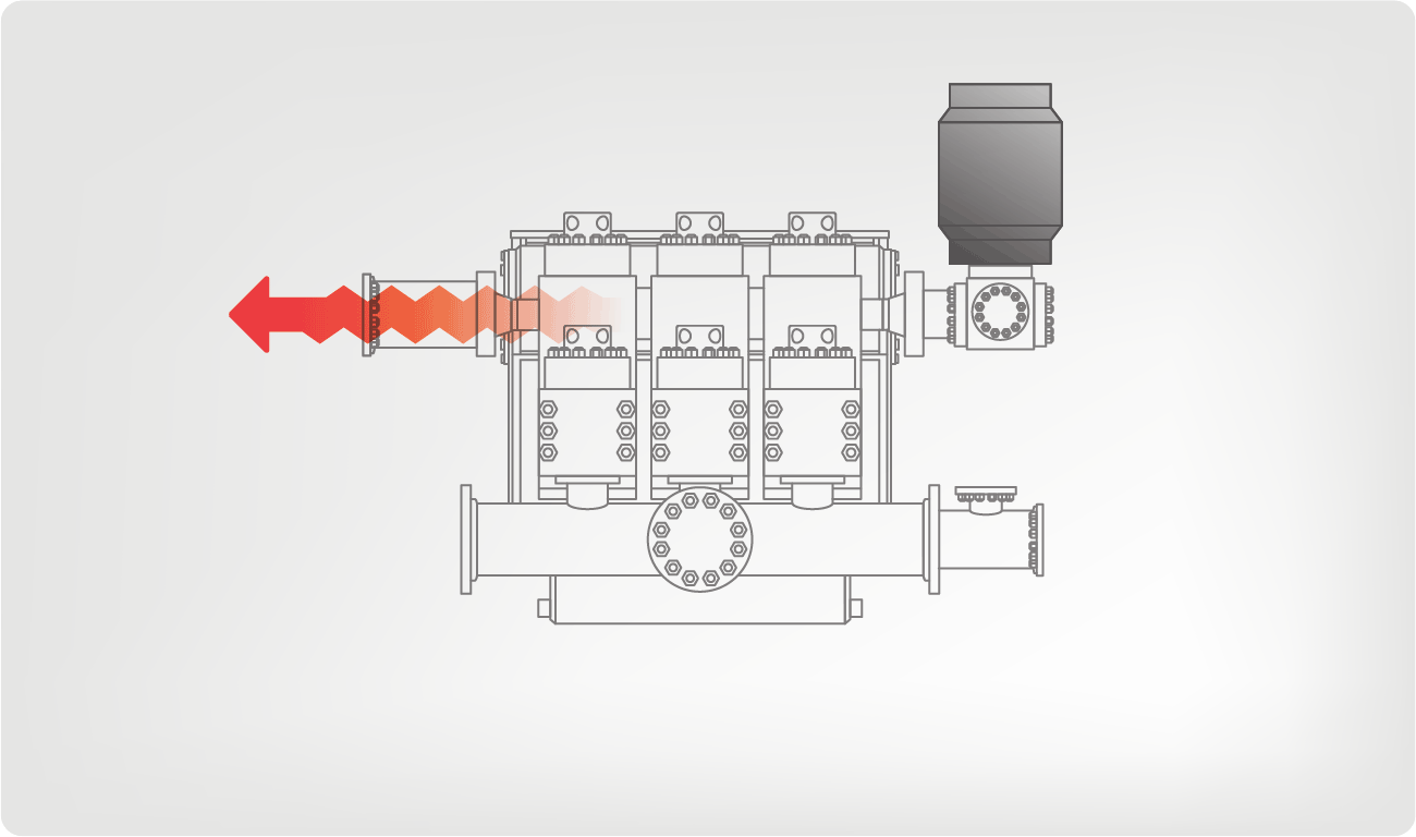
In some other embodiments, a downlink system comprises a device that causes the mud pumps to operate inefficiently or that causes at least a portion of the mud pumps to temporarily stop operating. For example, Figure 6 diagrammatically shows a pump inefficiency controller 601 attached to a mud pump 602a. Figure 6 shows three mud pumps 602a, 602b, 602c. Drilling rigs can include more or fewer than three mud pumps. Three are shown in Figure 6A for illustrative purposes.
Each of the mud pumps 602a, 602b, 602c draws mud from the mud storage tank 604 and pumps the mud into the standpipe 608. Ideally, the mud pumps 602a, 602b, 602c will pump at a constant flow rate. The pump inefficiency controller 601 is connected to the first mud pump 602a so that the controller 601 may affect the efficiency of the first mud pump 602a.
Figure 6B diagrammatically shows the internal pumping elements of the first mud pump 602a. The pumping elements of pump 602a include three pistons 621, 622, 623 that are used to pump the mud. For example, the third piston 623 has an intake stroke, where the piston 623 moves away from the intake valve 625, and mud is drawn from the mud tank into the piston chamber. The third piston 623 also has an exhaust stroke, where the piston 623 moves in the opposite direction and pushes the mud out an exhaust valve 626 and into the standpipe (608 in Figure 6A). Each of the other pistons 621, 622 has a similar operation that will not be separately described.
The first piston 621 includes a valve controller 628 that forms part of, or is operatively coupled to, the pump inefficiency controller (604 in Figure 6A). When it is desired to send a downlink signal, the valve controller 628 prevents the intake valve 627 on the first piston 621 from opening during the intake stroke. As a result, the first piston 621 will not draw in any mud that could be pumped out during the exhaust stroke. By preventing the intake valve 627 from opening, the efficiency of the first pump 603 is reduced by about 33%. The efficiency of the entire pumping system (including all three mud pumps 602a, 602b, 602c in the embodiment shown in Figure 6A, for example) is reduced by about 11 %.
By operating the pump inefficiency controller (604 in Figure 6A), the efficiency, and thus the flow rate, of the mud pumping system can be reduced. Intermittent or selective operation of the pump efficiency controller creates pulses in the mud flow rate that may be detected by sensors in the BHA.
One or more embodiments of a pump inefficiency controller may present some of the following advantages. An inefficiency controller may be coupled to any preexisting mud pump system. The downlink system may operate without the need to add any equipment to the pump system. The pump inefficiency controlled may be controlled by a computer or other automated process so that human error in the pulse generation is eliminated. Without human error, the downlink signal may be transmitted more quickly with a greater chance of the signal being received correctly on the first attempt.
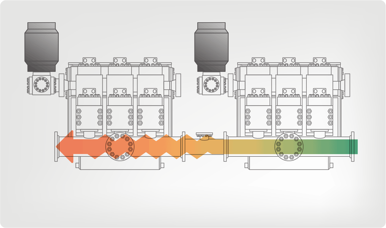
Figure 7A diagrammatically shows another embodiment of a downlink system 700 in accordance with the invention. A downlink pump 711 is connected to the mud manifold 707 that leads to the standpipe 708, but it is not connected to the mud tanks 704. As with a typical mud pump system, several mud pumps 702a, 702b, 702c are connected to the mud tank 704. Mud from the tank is pumped into the mud manifold 707 and then into the standpipe 708.
Pumps also have a "discharge," where fluid is pumped out of the pump. In Figure 7A, the intake end of each of the mud pumps 702a, 702b, 702c is connected to the mud storage tank 704, and the discharge end of each of the mud pumps 702a, 702b, 702c is connected to the mud manifold 707. Both the intake and the discharge of the downlink pump 711 are connected to the mud manifold 707.
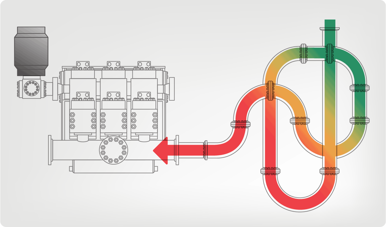
The downlink pump 711 shown in Figure 7A is a reciprocating piston pump that has intake and exhaust strokes like that described above with respect to Figure 6B. On the intake stroke, mud is drawn into the downlink pump 711, and on the exhaust stroke, mud is forced out of the downlink pump 711. The operation of the downlink pump 711 differs from that of the other pumps 702a, 702b, 702c in the mud pump system because it is not connected to the mud tank 704. Instead, both the intake and exhaust valves (not shown) of the downlink pump 711 are connected to the mud manifold 707. Thus, on the intake stroke, the downlink pump 711 draws in mud from the mud manifold 707, decreasing the overall flow rate from the mud pump system. On the exhaust stroke, the downlink pump 711 pumps mud into the mud manifold 707 and increases the overall flow rate from the mud pump system. In some embodiments, one valve serves as both the inlet and the discharge for the downlink pump. In at least one embodiment, a downlink pump is connected to the manifold, but it does not include any valves. The mud is allowed to flow in and out of the downlink pump through the connection to the manifold.
Selected operation of the downlink pump 711 will create a modulation of the mud flow rate to the BHA (not shown). The modulation will not only include a decrease in the flow rate-as with the bypass systems described above-but it will also include an increase in the flow rate that is created on the exhaust stroke of the downlink pump 711. The frequency of the downlink signal may be controlled by varying the speed of the downlink pump 711. The amplitude of the downlink signal may be controlled by changing the stroke length or piston and sleeve diameter of the downlink pump 711.
Those having ordinary skill in the art will also appreciate that the location of a downlink pump is not restricted to the mud manifold. A downlink pump could be located in other locations, such as, for example, at any position along the standpipe.
Figure 8 diagrammatically shows another embodiment of a downlink system 820 in accordance with the invention. The mud pumping system includes mud pumps 802a, 802b, 802c that are connected between a mud tank 804 and a standpipe 808. The operation of these components has been described above and, for the sake of brevity, it will not be repeated here.
The downlink system includes two diaphragm pumps 821, 825 whose intakes and discharges are connected to the mud manifold 807. The diaphragm pumps 821, 825 include a diaphragm 822, 826 that separates the pumps 821, 825 into two sections. The position of the diaphragm 822 may be pneumatically controlled with air pressure on the back side of the diaphragm 822. In some embodiments, the position of the diaphragm 822 may be controlled with a hydraulic actuator mechanically linked to diaphragm 822 or with an electromechanical actuator mechanically linked to diaphragm 822. When the air pressure is allowed to drop below the pressure in the mud manifold 807, mud will flow from the manifold 807 into the diaphragm pump 821. Conversely, when the pressure behind the diaphragm 822 is increased above the pressure in the mud manifold 807, the diaphragm pump 821 will pump mud into the mud manifold 807.
Figure 7 shows one piston downlink pump, and Figure 8 shows two diaphragm downlink pumps. The invention is not intended to be limited to either of these types of pumps, nor is the invention intended to be limited to one or two downlink pumps.
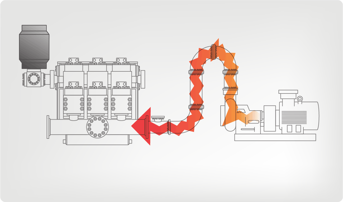
Figure 9 diagrammatically shows another embodiment of a downlink pump 911 in accordance with the invention. The discharge of the downlink pump 911 is connected to the mud manifold 907, and the intake of the downlink pump 911 is connected to the mud tank 904. The downlink pump 911 in this embodiment pumps mud from the mud tank 904 into the mud manifold 907, thereby increasing the nominal flow rate produced by the mud pumps 902a, 902b, 902c.
During normal operation, the downlink pump 911 is not in operation. The downlink pump 911 is only operated when a downlink signal is being sent to the BHA (not shown). The downlink pump 911 may be intermittently operated to create pulses of increased flow rate that can be detected by sensors in the BHA (not shown). These pulses are of an increased flow rate, so the mud flow to the BHA remains sufficient to continue drilling operations while a downlink signal is being sent.
One or more embodiments of a downlink pump may present some of the following advantages. A reciprocating pump enables the control of both the frequency and the amplitude of the signal by selecting the speed and stroke length of the downlink pump. Advantageously, a reciprocating pump enables the transmission of complicated mud pulse signals in a small amount of time.
A pump of this type is well known in the art, as are the necessary maintenance schedules and procedures. A downlink pump may be maintained and repaired at the same time as the mud pumps. The downlink pump does not require additional lost drilling time due to maintenance and repair.
Advantageously, a diaphragm pump may have no moving parts that could wear out or fail. A diaphragm pump may require less maintenance and repair than other types of pumps.
Advantageously, a downlink pump that is coupled to both the mud tanks and the standpipe may operate by increasing the nominal mud flow rate. Thus, there is no need to interrupt drilling operations to send a downlink signal.
In some embodiments, a downlink system includes electronic circuitry that is operatively coupled to the motor for at least one mud pump. The electronic circuitry controls and varies the speed of the mud pump to modulate the flow rate of mud through the drilling system.

Centrifugal pumps are used to transport fluids by the conversion of rotational kinetic energy to the hydrodynamic energy of the fluid flow. The rotational energy typically comes from an engine or electric motor. They are a sub-class of dynamic axisymmetric work-absorbing turbomachinery.volute chamber (casing), from which it exits.
Common uses include water, sewage, agriculture, petroleum, and petrochemical pumping. Centrifugal pumps are often chosen for their high flow rate capabilities, abrasive solution compatibility, mixing potential, as well as their relatively simple engineering.centrifugal fan is commonly used to implement an air handling unit or vacuum cleaner. The reverse function of the centrifugal pump is a water turbine converting potential energy of water pressure into mechanical rotational energy.
According to Reti, the first machine that could be characterized as a centrifugal pump was a mud lifting machine which appeared as early as 1475 in a treatise by the Italian Renaissance engineer Francesco di Giorgio Martini.Denis Papin built one using straight vanes. The curved vane was introduced by British inventor John Appold in 1851.
Like most pumps, a centrifugal pump converts rotational energy, often from a motor, to energy in a moving fluid. A portion of the energy goes into kinetic energy of the fluid. Fluid enters axially through eye of the casing, is caught up in the impeller blades, and is whirled tangentially and radially outward until it leaves through all circumferential parts of the impeller into the diffuser part of the casing. The fluid gains both velocity and pressure while passing through the impeller. The doughnut-shaped diffuser, or scroll, section of the casing decelerates the flow and further increases the pressure.
The color triangle formed by velocity vector u,c,w called "velocity triangle". This rule was helpful to detail Eq.(1) become Eq.(2) and wide explained how the pump works.
Fig 2.3 (a) shows triangle velocity of forward curved vanes impeller ; Fig 2.3 (b) shows triangle velocity of radial straight vanes impeller. It illustrates rather clearly energy added to the flow (shown in vector c) inversely change upon flow rate Q (shown in vector cm).
Vertical centrifugal pumps are also referred to as cantilever pumps. They utilize a unique shaft and bearing support configuration that allows the volute to hang in the sump while the bearings are outside the sump. This style of pump uses no stuffing box to seal the shaft but instead utilizes a "throttle bushing". A common application for this style of pump is in a parts washer.
In the mineral industry, or in the extraction of oilsand, froth is generated to separate the rich minerals or bitumen from the sand and clays. Froth contains air that tends to block conventional pumps and cause loss of prime. Over history, industry has developed different ways to deal with this problem. In the pulp and paper industry holes are drilled in the impeller. Air escapes to the back of the impeller and a special expeller discharges the air back to the suction tank. The impeller may also feature special small vanes between the primary vanes called split vanes or secondary vanes. Some pumps may feature a large eye, an inducer or recirculation of pressurized froth from the pump discharge back to the suction to break the bubbles.
A centrifugal pump containing two or more impellers is called a multistage centrifugal pump. The impellers may be mounted on the same shaft or on different shafts. At each stage, the fluid is directed to the center before making its way to the discharge on the outer diameter.
A common application of the multistage centrifugal pump is the boiler feedwater pump. For example, a 350 MW unit would require two feedpumps in parallel. Each feedpump is a multistage centrifugal pump producing 150 L/s at 21 MPa.
The energy usage in a pumping installation is determined by the flow required, the height lifted and the length and friction characteristics of the pipeline.
An oilfield solids control system needs many centrifugal pumps to sit on or in mud tanks. The types of centrifugal pumps used are sand pumps, submersible slurry pumps, shear pumps, and charging pumps. They are defined for their different functions, but their working principle is the same.
Magnetically coupled pumps, or magnetic drive pumps, vary from the traditional pumping style, as the motor is coupled to the pump by magnetic means rather than by a direct mechanical shaft. The pump works via a drive magnet, "driving" the pump rotor, which is magnetically coupled to the primary shaft driven by the motor.gland is needed. There is no risk of leakage, unless the casing is broken. Since the pump shaft is not supported by bearings outside the pump"s housing, support inside the pump is provided by bushings. The pump size of a magnetic drive pumps can go from few watts of power to a giant 1 MW.
The process of filling the pump with liquid is called priming. All centrifugal pumps require liquid in the liquid casing to prime. If the pump casing becomes filled with vapors or gases, the pump impeller becomes gas-bound and incapable of pumping.
In normal conditions, common centrifugal pumps are unable to evacuate the air from an inlet line leading to a fluid level whose geodetic altitude is below that of the pump. Self-p


 8613371530291