
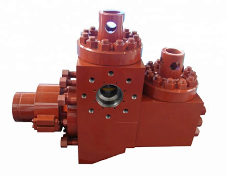
mud pump fluid end assemblies free sample
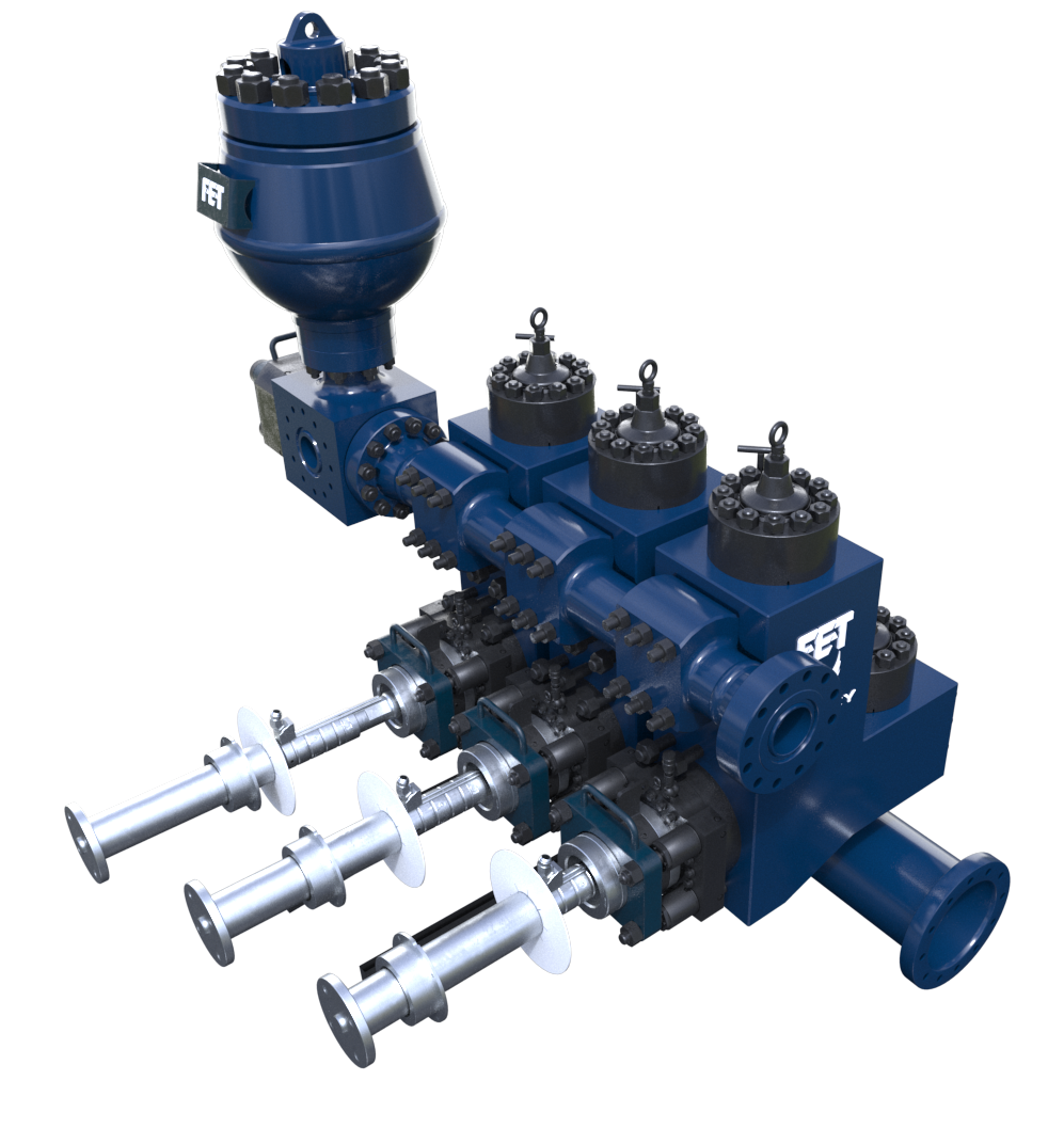
Fluid end modules are workhorses of mud pump systems, but extreme working environments make them especially vulnerable to stress, wear and damage. In choosing durable fluid end parts that resist cracking and corrosion, you’re making a wise long-term investment for your operations.
Forum offers a full line of high-quality fluid end modules that are entirely manufactured in the United States. Designed for the challenges of higher-pressure drilling, they are crafted with industry-leading materials and technologies to resist cracking and reduce stress concentrations for significantly longer life. Complementary features include our industry-leading P-Quip® liner retention and rod systems. Additional benefits and features include:

A wide variety of mud pump fluid end modules options are available to you, such as 1 year, not available and 3 years.You can also choose from new, mud pump fluid end modules,As well as from energy & mining, construction works , and machinery repair shops. and whether mud pump fluid end modules is 1.5 years, 6 months, or unavailable.

The invention relates to an assembly for quickly securing and releasing a component to a pump housing and more particularly to a retainer assembly for releasably mounting a piston liner within a hydraulic cylinder on the module of a pump.
Heavy duty large horsepower pumps are used to pump fluids or slurries with entrained solids. In the oil industry, for example, slush or mud pumps are used to pump viscous fluids, such as drilling muds, cement, or other well fluids. Although mud pumps may be either centrifugal or reciprocating type pumps, typically mud pumps are reciprocating pumps using one or more pistons and hydraulic cylinders with liners to generate the high pressures required to pump these viscous fluids in and out of the well.
Mud pumps include a fluid end and a power end. In the fluid end of one type of a triplex mud pump, for example, there are three sets of suction modules and discharge modules in fluid communication. A suction manifold is connected to the fluid inlets of the suction modules for receiving fluids and passing those fluids to each of the suction modules. A discharge manifold is connected to the fluid outlets of the discharge modules for discharging the pumped fluids. Each module encloses a set of flow passages with check valves for controlling the direction of flow of the fluids. A check valve is disposed at the suction module fluid inlet to only allow fluids to enter the suction module inlet end of the module and another check valve is disposed at the discharge module fluid outlet to only allow fluids to exit the the discharge module for flow into the discharge manifold.
Each discharge module includes a liner retainer flange attached to the discharge module. The liner retainer flange attaches to a replaceable liner within which a pump piston reciprocates. The piston is a generally cylindrical steel member having a polymer, such as polyurethane, bonded to its outer diameter for sealingly engaging the inner cylindrical wall of the liner to ensure a fluid tight seal required for drawing the low pressure fluids through the suction manifold and module flow passages. The seal integrity must be maintained to withstand the high discharge pressure on the discharge stroke. The power end contains the gears that reciprocate the pump piston within the liner for pumping the fluid through the module passages in the fluid end and thence out the discharge valve.
In operation, on the suction stroke, the pump piston draws fluids through the suction manifold and suction valve as the piston strokes within the liner. On the discharge stroke, the check valve in the discharge module opens simultaneously as the suction valve closes preventing suction back flow into the suction module. Fluid in the liner is compressed and pressure is built up until the pressure overcomes well bore pressure so as to pump the mud into the well. The piston then reverses for another suction stroke whereby the check valve in the suction module opens and the discharge valve closes simultaneously, the piston now making a suction stroke.
As the piston reciprocates within the liner, friction wears the liner. Further, the fluid passing through the fluid end includes particulates and other solids which wear away and destroy the liner and piston. When the liner and piston degrade, the fluid seal is lost and the pump becomes much less efficient. Also, the reciprocation of the piston in the liner causes pulsations that over time cause the liner to become loose within the containment of the liner retainer flange thus resulting in a degradation of the seal at the face of the liner and the seal at the face of the liner wear plate. Therefore, it is important to be able to replace the liner as a part of routine maintenance (or when emergencies occur from seal failure while drilling) to ensure that the pump operates efficiently and can control well pressure. It is also important to have a means for fastening the liner to the liner retainer flange so as to ensure that the liner remains firmly secured despite extended reciprocation of the piston assembly within the liner.
Typically each liner retainer flange, and the cradle of the pump power end are all secured to the fluid end module by studs and threaded connections. Because of the environment in which the mud pump operates and the corrosive nature of the fluids being pumped, the studs and threaded connections, such as nuts, become corroded and are difficult to unthread for the replacement of the liner. Often, the threaded connections have been over tightened, making it even more difficult to unthread. Where the liner is retained by an end cap, a steel bar is inserted into a guide hole in the side of the end cap and then the cap is unscrewed using a significant amount of torque. This end cap is very heavy as it must have sufficient strength to keep the liner from moving, even with pressures up to 7500 psi. Where a nut or end cap resists unscrewing, a sledge hammer is used to hammer on a socket wrench or a special hammer wrench is used to loosen the nut or cap. Such activity is obviously dangerous. In some regions of the world local laws prohibit the use of sledge hammers for personnel safety reasons or to avoid the risk of an explosion due to sparks.
Prior art liner retention systems include spring mechanisms around each stud with an end flange for securing the liner against a fluid end module. Hydraulic pressure is applied to the spring mechanism of each stud by a small hydraulic pump to remove the clamping force of the spring mechanism. The release of the clamping force allows the removal of the clamping flange of the liner retention system. Individually actuated spring loaded studs cause an uneven pressure to be applied to the clamping flange. Further, the clamping force is limited because of the limited space available to hold numerous springs.
The liner retainer assembly of the present invention includes a liner retainer flange that is mounted on the discharge module of the fluid end of a pump. A pressure actuated hydraulic clamping piston with related actuated, conical dished washers and necessary static and sliding seals is disposed within the retainer flange . The hydraulic pressure actuated clamping piston is configured to receive and hold the liner. The hydraulic clamping piston and an end cap maintain the liner in contact with the module during actuation. The hydraulic clamping cylinder includes a counterbore which is divided by the hydraulic piston into a fluid cavity and a spring cavity. The spring cavity houses a plurality of springs which bias the hydraulic piston, end cap, and liner towards the module, thus providing a strong clamping securing force when the hydraulic pressure is released. The fluid cavity communicates with a supply of hydraulic fluid for biasing the hydraulic piston away from the module to activate the springs. By pressurizing the fluid cavity, the springs are compressed so as to disengage the liner retaining end cap from the liner and allow the unthreading of the liner end cap to then remove the liner.
The liner retainer assembly permits preloading or prestressing of the liner against the module of the fluid end of the pump so that the liner will not loosen upon the reciprocation of the pump piston within the liner. Further, the liner may be easily secured and unsecured from the module without the necessity of a sledge hammer or other methods for applying excessive amounts of torque to a securing fitting. The assembly of the present invention permits the easy and quick replacement of the liner as necessary.
Referring first to FIGS. 1 and 2, there is shown a fluid end module 10 and a cradle 28 of the pump power end. The pump is of the type used to pump fluids, such as drilling muds, cement or the like. Pumps of this type are well known. A wear plate 14 defines a bore 16 which leads into liner 20. The module 10 is used for the transfer of fluid from the suction manifold and suction module (not shown) to the discharge manifold (not shown) and discharge module.
An exemplary liner retaining flange assembly 18 of the present invention is used to secure liner 20 within a hydraulic cylinder 30 mounted on module 10 and liner retainer flange 22. Those of skill in the art will understand that a pump piston (not shown) attached to the power end of the pump is reciprocated within the liner 20 to effect the desired pumping action to flow fluid through the fluid end module 10 of the pump. Hydraulic cylinder 30 provides an open end into which the liner 20 is inserted. Module 10 also provides a counterbore 12 for the adjacent wear plate 14 against which it is desired to retain the liner 20 during operation of the pump piston. It can be appreciated that the purpose of wear plate 14 is to avoid the end of liner 20 wearing module 10 due to the reciprocation of the piston within liner 20. However, wear plate 14 may cause wear to the module 10 if the liner 20 is not securely affixed. Wear plate 14 may be replaced should that wear become excessive. It is noted that the end of the liner 20 adjacent the wear plate 14 includes an internal annular groove 59 with seal member 61 for sealingly engaging the wear plate 14 and the other open end 15 of liner 20 includes an external annular load-bearing shoulder 60 which retains end cap 64 (FIG. 2).
The hydraulic cylinder 30 includes a threaded, reduced diameter portion 24 and an enlarged diameter portion 32. Reduced diameter portion 24 is secured in a threaded or splined relation at 23 to liner retainer flange 22 that is located in an abutting relation to the module 10. Bolted studs 26 secure the cradle 28 of the pump power end, the liner retaining flange 22 and hydraulic cylinder 30 to module 10.
The enlarged portion 32 of hydraulic cylinder 30 includes an inner clearance cavity 33 which has a reduced diameter neck, forming a hydraulic cavity 58 to activate hydraulic piston 42 which in turn compresses springs 56 which are restrained from escaping from the spring cavity 35 by retainer ring 48. Hydraulic sealing is accomplished by sealing rings 39 and 49. End cap 64 is held in place with external threads 46. A hydraulic fluid port and fitting 38 is disposed through the wall of enlarged diameter portion 32.
When these components are assembled, the annular flange 44 of piston 42 forms hydraulic cavity 58 and outer spring cavity 35. The hydraulic fluid port and fitting 38 communicates with hydraulic cavity 58 for applying hydraulic pressure to flange 44. The spring cavity 35 houses a plurality of axially compressible Belleville springs or washers 56. Retainer ring 48 has external threads 50 which threadingly mate in a complimentary fashion with the internal threads 34 of enlarged diameter portion 32. The washers 56 bear against the retainer ring 48 and annular flange 44. Enough springs are used so as to insure sufficient force is generated to prevent movement of liner 20 when pump pressure is at maximum. The retainer ring 48 secures the washers 56 and hydraulic piston 42 within the enlarged diameter portion 32 of hydraulic cylinder 30. O-ring 49 provides a fluid-tight seal between the piston 42 and enlarged diameter portion 32.
Upon assembly as shown in FIG. 1, hydraulic piston 42 has previously been inserted into enlarged diameter portion 32 of cylinder 30 to form cavities 58 and 35. Belleville washers 56 are inserted into outer spring cavity 35 and retainer ring 48 is threaded into place. The liner 20 is inserted into the outer hydraulic cylinder 30 of liner retaining assembly 18 so that the end of the liner 20 with seal 61 abuts wear plate 14.
Referring particularly to FIG. 2, the retaining assembly 18 is shown ready to secure the liner 20 in place. A hydraulic hose 62 is secured to the external port and fitting 38 for supplying hydraulic fluid to inner hydraulic cavity 58. As fluid pressure is supplied to cavity 58, fluid pressure is exerted against flange 44 urging piston 42 outward toward retainer ring 48. As annular flange 44 of piston 42 is so moved, springs 56 are axially compressed. As springs 56 are compressed, the threaded end 46 of piston 42 extends further away from wear plate 14 and module 10.
In the outward and extended position of piston 42, end cap 64 is threaded onto the threaded end 46 of the piston 42 so the threads 46 mate with the threads 66 of end cap 64. End cap 64 need only be hand tightened. It is noted that liner load bearing shoulder 60 mates with the shoulder 68 on end cap 64.
Referring now to FIG. 3, the retaining assembly 18 is shown completely assembled with the liner 20 securely affixed within the hydraulic cylinder 30. Once end cap 64 has been affixed, the fluid within the hydraulic cavity 58 is evacuated through port and fitting 38 permitting the springs 56 to bias flange 44 toward wear plate 14 and module 10 and bias end cap 64 against the other end 15 of liner 20. As the hydraulic pressure in the hydraulic cavity 58 is released, stored energy from the compression of springs 56 is released to load the liner 20 longitudinally. As a result, the energy stored by compressing springs 56 is transmitted to the liner 20 in order to load it longitudinally against wear plate 14 and module 10.
In order to remove the liner 20, the procedure is substantially reversed. Fluid is introduced into the hydraulic cavity 58 through port and fitting 38 in the same manner as previously described to compress springs 56 and external piston 42. Once spring forces are removed, end cap 64 may then be unthreaded. Fluid is bled off, springs 56 are decompressed and the unit is stabilized.
It is noted that the arrangement of the present invention permits a liner to be replaced rapidly and easily and without the use of extra tools or having to apply excessive torque. Further, a prestress force is applied to the liner 20 so that it is longitudinally compressed against wear plate 14 and module 10. This load or prestress securely holds the liner 20 against the wear plate 14 despite repeated reciprocation of the pump piston within liner 20.
In this embodiment, hydraulic cylinder 36 defines a plurality of individual piston chambers 72. There are 4, 6, or 8 chambers 72 (depending on the holding force required) which are azimuthally spaced around hydraulic cylinder 36. Each piston chamber 72 contains a wear cylinder sleeve 101 with an individual piston 74 that is reciprocably disposed therein. Wear sleeve 101 includes threaded bores 103 for receiving bolts to assist in the replacement of sleeves 101 when excessive wear has occurred. Each piston 74 provides an elongated shaft 76 and a radially extending flange 78 so that when disposed within the chamber 72, the chamber 72 is divided into a spring retaining chamber 80 and fluid chamber 82. The shaft 76 of the piston 74 is threaded at 84 for threadingly receiving a nut 86. Fluid may be introduced into the fluid chamber 82 through an associated hydraulic fluid port and external fitting 38.
A cover 88 is placed over the open end 15 of liner 20, the cover 88 having a central opening 90 through which liner 20 is disposed. The cover 88 also includes apertures 92 for the disposal of each piston shaft 76. The cover 88 serves to provide a solid surface against which Belleville springs 94 may be compressed. O-ring seals 96 surround the flange 78 of each piston 74 to ensure fluid sealing.
An end cap 98 is shown disposed over the cover 88. The end cap 98, like the cover 88, provides apertures 100 for receiving piston shafts 76. However, the central aperture 102 is only large enough to permit a portion of the liner 20 to be disposed therethrough, creating a shoulder 104 which mates with the shoulder 60 of liner 20.
Referring particularly to FIG. 5, a plurality of fluid passages 106 are provided in hydraulic cylinder 36 which interconnect and communicate with each piston chamber 72 and each of the ports and fittings 38 on the hydraulic cylinder 36. The fluid interconnection permits all of the fluid chambers 82 (FIG. 4) to be filled with fluid by using only one or a few of the hydraulic fluid ports and fittings 38 for injecting fluid. The common communication with all fluid chambers 82 also allows the common hydraulic actuation of all the pistons 74 (FIG. 4).
In operation as shown in FIG. 4, the liner 20 is installed and removed in a manner similar to that described with respect to liner retaining assembly 18. Fluid is introduced into each individual fluid chamber 82 urging the associated piston 74 to move toward the open end 15 of liner 20. Energy is stored through axial compression of the Belleville springs 94. The end cap 98 is placed onto the liner open end 15 so that the shoulder 104 engages shoulder 60 of liner 20. Nuts 86 are then tightened onto each piston 74. Again, the nuts need only be hand tightened. Fluid is then evacuated from the fluid chambers 82 and the Belleville springs 94 bias pistons 74 toward the wear plate 14 and the module 10, thus loading liner 20 longitudinally against wear plate 14 and module 10.
This section is intended to introduce the reader to various aspects of art that may be related to various aspects of the presently described embodiments. This discussion is believed to be helpful in providing the reader with background information to facilitate a better understanding of the various aspects of the present embodiments. Accordingly, it should be understood that these statements are to be read in this light, and not as admissions of prior art.
In order to meet consumer and industrial demand for natural resources, companies often invest significant amounts of time and money in finding and extracting oil, natural gas, and other subterranean resources from the earth. Particularly, once a desired subterranean resource such as oil or natural gas is discovered, drilling and production systems are often employed to access and extract the resource. These systems may be located onshore or offshore depending on the location of a desired resource. Further, such systems generally include a wellhead assembly mounted on a well through which the resource is accessed or extracted. These wellhead assemblies may include a wide variety of components, such as various casings, valves, pumps, fluid conduits, and the like, that control drilling or extraction operations.
As will be appreciated, drilling and production operations employ fluids referred to as mud or drilling fluids to provide lubrication and cooling of the drill bit, clear away cuttings, and maintain desired hydrostatic pressure during operations. Mud can include all types of water-based, oil-based, or synthetic-based drilling fluids. Mud pumps can be used to move large quantities of mud from surface tanks, down thousands of feet of drill pipe, out nozzles in the bit, back up the annulus, and back to the tanks. Operations come to a halt if the mud pumps fail, and thus, reliability under harsh conditions, using all types of abrasive fluids, is of utmost commercial interest.
Certain aspects of some embodiments disclosed herein are set forth below. It should be understood that these aspects are presented merely to provide the reader with a brief summary of certain forms the invention might take and that these aspects are not intended to limit the scope of the invention. Indeed, the invention may encompass a variety of aspects that may not be set forth below.
Some embodiments of the present disclosure generally relate to a self-aligning mud pump apparatus. In one embodiment, the self-aligning mud pump apparatus includes a housing and a rotatable crankshaft disposed in the housing. The self-aligning mud pump apparatus can include a crosshead disposed in the housing, as well as a crosshead guide disposed in the housing to constrain movement of the crosshead. The self-aligning mud pump apparatus can include a hub disposed in the housing and disposed on the crankshaft for converting a rotating motion of the crankshaft to a reciprocating motion of the crosshead via a connecting rod having a first end coupled to the hub and a second end coupled to the crosshead. The connecting rod can be coupled to the crosshead such that the connecting rod has five degrees of freedom with respect to the crosshead guide.
Certain embodiments of the present disclosure generally relate to a method for assembling self-aligning components of a pump. The method can include providing a crosshead of the pump and coupling a connecting rod to the crosshead with a first socket joint that allows three rotational degrees of freedom between the connecting rod and the crosshead. The method can also include coupling a piston to the crosshead with a second socket joint that allows three rotational degrees of freedom between the piston and the crosshead.
Various refinements of the features noted above may exist in relation to various aspects of the present embodiments. Further features may also be incorporated in these various aspects as well. These refinements and additional features may exist individually or in any combination. For instance, various features discussed below in relation to one or more of the illustrated embodiments may be incorporated into any of the above-described aspects of the present disclosure alone or in any combination. Again, the brief summary presented above is intended only to familiarize the reader with certain aspects and contexts of some embodiments without limitation to the claimed subject matter.
FIG. 6B shows a schematic of an alternative crankshaft of a mud pump such as shown in FIG. 6A in accordance with one or more implementations described herein.
FIG. 6C shows a schematic of an alternative crankshaft of a mud pump such as shown in FIG. 6A in accordance with one or more implementations described herein.
FIG. 7A shows a schematic of a modular mud pump unit that can be used alone or in combination with a mirror-image modular unit, as shown in FIG. 7B, in accordance with one or more implementations described herein.
FIG. 8A shows a partial cross-section of a crosshead and connecting rod interface of a mud pump, in accordance with one or more implementations described herein.
FIG. 8C shows a partial cross-section of a crosshead and connecting rod interface of a mud pump, in accordance with one or more implementations described herein.
When introducing elements of various embodiments, the articles “a,” “an,” “the,” and “said” are intended to mean that there are one or more of the elements. The terms “comprising,” “including,” and “having” are intended to be inclusive and mean that there may be additional elements other than the listed elements. Moreover, any use of “top,” “bottom,” “above,” “below,” other directional terms, and variations of these terms is made for convenience, but does not require any particular orientation of the components.
The present disclosure describes a variety of design changes to mud pump kinematics and construction to result in a less rigid, more robust and reliable mud pump. In a first embodiment described in greater detail below, load balancing is achieved by spacing hubs along the crankshaft of the mud pump with the bull gears disposed opposite one another, on the outermost ends of the crankshaft adjacent to the housing. In such an embodiment, the hubs are disposed along the crankshaft between the bull gears. In a second embodiment described in greater detail below, a novel crosshead design enables connection to both connecting rod and piston, resulting in self-aligning components with at least three degrees of rotational freedom and two degrees of translational freedom. In a third embodiment described in greater detail below, the present disclosure also includes various seal and/or piston sleeve assemblies that can be applied to a plunger style piston.
Generally speaking, FIG. 1 illustrates a wellsite system in which the disclosed mud pump can be employed. The wellsite system of FIG. 1 may be onshore or offshore. In the wellsite system of FIG. 1, a borehole 11 may be formed in subsurface formations by rotary drilling using any suitable technique. A drill string 12 may be suspended within the borehole 11 and may have a bottom hole assembly 100 that includes a drill bit 105 at its lower end. A surface system of the wellsite system of FIG. 1 may include a platform and derrick assembly 10 positioned over the borehole 11, the platform and derrick assembly 10 including a rotary table 16, kelly 17, hook 18 and rotary swivel 19. The drill string 12 may be rotated by the rotary table 16, energized by any suitable means, which engages the kelly 17 at the upper end of the drill string 12. The drill string 12 may be suspended from the hook 18, attached to a traveling block (not shown), through the kelly 17 and the rotary swivel 19, which permits rotation of the drill string 12 relative to the hook 18. A top drive system could alternatively be used, which may be a top drive system well known to those of ordinary skill in the art.
In the wellsite system of FIG. 1, the surface system may also include drilling fluid 26 (also referred to as mud) stored in a pit/tank 27 at the wellsite. A pump 29 supported on a skid 28 may deliver the drilling fluid 26 to the interior of the drill string 12 via a port in the swivel 19, causing the drilling fluid to flow downwardly through the drill string 12 as indicated by the directional arrow 8. The drilling fluid 26 may exit the drill string 12 via ports in a drill bit 105, and circulate upwardly through the annulus region between the outside of the drill string 12 and the wall of the borehole 11, as indicated by the directional arrows 9. In this manner, the drilling fluid 26 lubricates the drill bit 105 and carries formation cuttings up to the surface, as the drilling fluid 26 is returned to the pit/tank 27 for recirculation. The drilling fluid 26 also serves to maintain hydrostatic pressure and prevent well collapse. The drilling fluid 26 may also be used for telemetry purposes. A bottom hole assembly 100 of the wellsite system of FIG. 1 may include logging-while-drilling (LWD) modules 120 and 120A and/or measuring-while-drilling (MWD) modules 130 and 130A, a roto-steerable system and motor 150, and the drill bit 105.
FIG. 2 shows a cutaway side view of a prior art mud pump, illustrating various components of the power assembly, the portion of the pump that converts rotational energy into reciprocating motion. A pump as shown in FIG. 2 could be used as pump 29 of FIG. 1, although many other mud pumps, including those with designs described below in accordance with certain embodiments of the present technique, could instead be used as pump 29. Pinion gears 52 along a pinion shaft 48 drive a larger gear referred to as a bull gear 42 (e.g., a helical gear or a herringbone gear), which rotates on a crankshaft 40. Pinion shaft 48 is turned by a motor (not shown). The crankshaft 40 turns to cause rotational motion of hubs 44 disposed on the crankshaft 40, each hub 44 being connected to or integrated with a connecting rod 46. By way of the connecting rods 46, the rotational motion of the crankshaft 40 (and hub 44 connected thereto) is converted into reciprocating motion. The connecting rods 46 couple to a crosshead 54 (a crosshead block and crosshead extension as shown may be referred to collectively as the crosshead 54 herein). The crosshead 54 moves translationally constrained by guide 57. Pony rods 60 connect the crosshead 54 to a piston 58. In the fluid end of the pump, each piston 58 reciprocates to move mud in and out of valves in the fluid end of the pump 29.
Using conventional mud pump designs, pumping drilling fluids at above 50% capacity and/or for longer periods of time accelerates pump failure. With any combination of the design changes described below implemented, a mud pump may be operable at a higher capacity for longer periods of time. The design changes disclosed herein include load balancing embodiments, self-aligning power assembly embodiments, and piston sealing implementations.
Turning now to FIG. 3, a load-balanced mud pump is shown. Within a housing 33, a pinion shaft 48 is disposed, supported in roller bearings 51 at each opposing end of pinion shaft 48. Pinion shaft 48 is driven by a motor (not shown). A pair of pinion gears 52 rotate on the pinion shaft 48. Pinion gears 52 engage with bull gears 42, each of which rotate on a crankshaft 40. As can be seen in FIG. 3, the bull gears 42 are positioned adjacent to the housing 33 along the crankshaft 40, and pinion gears 52 are likewise positioned adjacent to the housing 33 along the pinion shaft 48. A plurality of hubs 44 are positioned along the crankshaft 40 between the bull gears 42 without any hubs positioned between the bull gears 42 and the walls of the housing 33.
By separating the largest, heaviest gears, i.e., the bull gears 42, toward the exterior along the crankshaft, an optimized load balance is accomplished. The position of the pinion gears 52 being substantially toward the exterior along the pinion shaft 48 further contributes to the load balance of the pump overall. In other embodiments, pinion gears 42 and bull gears 52 may be positioned further away from the walls of the housing while still remaining closer to the walls of the housing than to a midpoint along the pinion shaft 48 and crankshaft 40 respectively.
Each hub 44 is integrated with a connecting rod 46 (typically a forged metal) that couples at an interface to a crosshead 54, which will be discussed in further detail below. In turn, each crosshead 54 also couples at another interface to a plunger piston 58 (shown in FIG. 9A). Crosshead 54 is constrained in direction of movement by a guide, not shown in FIG. 3, discussed further below. In the fluid end, plunger piston 58 draws mud in and out by way of inlet 59 and outlet 61. Valve pots 63 are the machine openings to the fluid end of the mud pump.
FIG. 4A shows a schematic of a mud pump in accordance with one or more implementations described herein. Motors 31 couple operatively to a series of gear wheels 32. The gear wheels 32 rotate the pinion shaft 48. Pinion shaft 48 is supported in the housing 33 by a pinion shaft roller bearing 51 in the wall of housing 33 at either end of the pinion shaft 48. The pinion gears 52 are rotatable on pinion shaft 48. Pinion gears 52 engage bull gears 42, which are rotatable on the crankshaft 40. Crankshaft 40 is supported in the housing 33 on crankshaft roller bearings 56 in the walls of housing 33 at either end of the crankshaft 40. Bull gears 42 are positioned along crankshaft 40 at opposite ends of the crankshaft 40, adjacent to the walls of housing 33. Hubs 44 are positioned along the crankshaft between the bull gears 42. In the embodiment shown, the hubs 44 are spaced about evenly across the crankshaft 40. The crankshaft 40 passes through not the center of each hub, but at a position radially offset from the center of each hub, such that the hubs 44 are out of phase relative to one another to drive the pistons. Alternatively, embodiments are envisioned in which spacing is optimized for load balancing based on the weight and/or size of each individual hub 44 and connecting rod 46. Additionally, four hubs 44 are shown in FIG. 4A, though pumps having as few as two, or as many as five, hubs for driving reciprocal motion of crossheads are likewise contemplated in the present disclosure.
FIG. 4B shows a schematic of an alternative of a mud pump in accordance with one or more implementations described herein. Motors 31 couple operatively to a series of gear wheels 32. The gear wheels 32 rotate two separate pinion shafts, denoted pinion shafts 48A and 48B in FIG. 4B. Separate pinion shafts 48 enable easier repair of pump components, as there is sufficient room to, if needed, remove each pinion shaft independently. By comparison a single longer length pinion shaft may be of such a length as to be physically difficult to remove once the pump is rigged up in limited space at a wellsite. Pinion shafts 48 are supported in the housing 33 by at least a pair of pinion shaft roller bearings 51A and 51B in the wall of housing 33 on both sides of the housing 33. In order for each pinion shaft to rotate without wobbling under weight, at least two points of mechanical support are used. Thus, a mechanical support 55 affixed to (or integrated with) the housing 33 provides support to pairs of roller bearings 51A and 51B. A pinion gear 52 is rotatable on each separate pinion shaft 48. Pinion gears 52 engage bull gears 42, each of which is rotatable on the crankshaft 40. The positioning of the bull gears 42 and hubs 44 along the crankshaft 40 are, in FIG. 4B, similar to the configuration as described with respect to FIG. 4A.
FIG. 4C shows a schematic of an alternative of a mud pump in accordance with one or more implementations described herein. Motors 31 couple operatively to a series of gear wheels 32. The gear wheels 32 rotate two separate pinion shafts 48 coupled together at a coupler 65. The coupler 65 serves two purposes. First, the coupler 65 mechanically fastens the two pinion shafts 48 to one another such that the length of the fastened pinion shafts 48 is mechanically supported. Second, the coupler 65 serves to synchronize rotation of pinion shafts 48A and 48B, allowing the pinion shafts 48A and 48B to be rotated with respect to one another during assembly for proper rotational phase difference between the hubs 44 of the two shafts to drive the pistons. By disconnecting the coupler 65, each pinion shaft 48 can be replaced independent of the other. Pinion shafts 48 are supported in the housing 33 by at least a pair of pinion shaft roller bearings, denoted 51A and 51B, in the wall of housing 33 on both sides of the housing 33. As above, in order for each pinion shaft to rotate without wobbling under weight, at least two points of mechanical support are used. Thus, mechanical support 55 affixed to (or integrated with) the housing 33 provides an anchoring point for pairs of roller bearings 51A and 51B to hold up each pinion shaft 48A and 48B. A pinion gear 52 is rotatable on each separate pinion shaft 48. Pinion gears 52 engage bull gears 42, each of which is rotatable on the crankshaft 40. The positioning of the bull gears 42 and hubs 44 along the crankshaft 40 are, in FIG. 4C, similar to the configuration as described with respect to FIG. 4A.
In embodiments employing two independent separate pinion shafts, as shown in FIGS. 4B and 4C, the two segments of the pinion shaft 48 are indirectly rotationally coupled one to the other through the first bull gear 42, the crankshaft 40, and the second bull gear 42, respectively. In such embodiments, the two segments of pinion shaft 48 do not directly engage one another.
FIG. 5A shows a schematic of a crankshaft of a mud pump in accordance with one or more implementations described herein. The pinion shaft 48 and pinion gear 52 may be configured as in any of the embodiments described above. As can be seen in FIG. 5A, the bull gears 42 are positioned adjacent to the housing 33 along the crankshaft 40. Pinion gears 52 may likewise be positioned adjacent to the housing 33 along the pinion shaft 48. A plurality of hubs 44 are positioned along the crankshaft 40 between the bull gears 42. An optimized weight load balance is accomplished by separating the largest, heaviest gears, the bull gears 42. In the embodiment of FIG. 5A, the crankshaft 40 spans a length less than the width of the housing 33. In lieu of roller bearings 56 in the walls of the housing 33 to support the crankshaft 40, mechanical supports 62 are attached to (or integrated with) the housing 33 to support the crankshaft 40. Lubricated pads 64 affix to the mechanical supports 62 so that the crankshaft 40 rotates freely. FIG. 5B shows a cross-section of an example of a lubricated pad, as an alternative for a roller bearing, for use in the embodiment shown in FIG. 5A. The lubricated pad 64 may include a lower pad 64A and an upper pad 64B, each conformed to curve around crankshaft 40. In a preferred embodiment, the lubricated pads are offset by 30° relative to a horizontal plane running through the crankshaft 40, as shown. The surface of lower pad 64A and upper pad 64B are lubricated. Additional lubricant can be added to the surfaces in contact with the crankshaft 40 in the gap between lower pad 64A and upper pad 64B.
FIG. 6A shows a schematic of an alternative of a mud pump in accordance with one or more implementations described herein. Load balancing is achieved in the embodiment of FIG. 6A by positioning the bull gears 42 adjacent to one another, centered on the crankshaft 40 and having none of the hubs 44 positioned on the crankshaft 40 therebetween. Motors 31 couple operatively to a series of gear wheels 32. The gear wheels 32 rotate pinion shaft 48. Pinion shaft 48 is supported in the housing 33 by pinion shaft roller bearings 51 in the walls of housing 33 on both sides of the housing 33. Pinion gears 52A and 52B are rotatable on pinion shaft 48, and are positioned adjacent to one another without engaging one another. The pinion gears 52A and 52B may be helical in design, as shown in FIG. 6B. Pinion gears 52 engage bull gears 42, each of which is rotatable on the crankshaft 40. In the embodiment of FIG. 6A, the crankshaft 40 spans a length less than the width of the housing 33. In lieu of roller bearings 56 in the walls of the housing 33 to support the crankshaft 40, mechanical supports 62 are attached to or integrated with the housing 33 to brace or support the crankshaft 40, and lubricated pads 64, such as those shown in FIG. 5B, affix to the mechanical supports 62 such that the crankshaft 40 rotates freely.
In the embodiment shown in FIG. 5A, four hubs 44 are shown, and three mechanical supports 62 are shown between the hubs 44. In the embodiment shown in FIG. 6A, four hubs 44 are shown and four mechanical supports 62 are shown. As with the previously described embodiments, pumps having as few as two, or as many as five, hubs are likewise contemplated in the present disclosure, along with a number of mechanical supports to adequately support the weight of the hubs 44 along the crankshaft 40, as can be readily determined by one of ordinary skill in the art.
FIG. 6C illustrates an alternative embodiment, having bull gears 42 centered along the crankshaft relative to the walls of the housing 33, with hubs 44 disposed along crankshaft 40 axially away from each of the bull gears 42. Mechanical supports 62 extend from the housing 33 to positions between hubs 44. Any numerical combination of hubs and mechanical supports is contemplated by the present disclosure, to the extent that the mechanical supports 62 adequately bear the load of the crankshaft bearing the bull gears 42 and hubs 44. The load is balanced across the length of the crankshaft so as to minimize wobble during high or full capacity usage of the pump.
FIG. 7A shows a schematic of a modular unit that, when coupled with a mirror-image modular unit, is operable as a mud pump in accordance with one or more implementations described herein. By providing independent modules of mud pump power end components, the overall mud pump is scalable. Expensive downtime is reduced with quick repair by interchanging modules, should any component in one module fail. The interchangeable mud pump module shown in FIG. 7A is contained within a housing 33, and a mechanical support 55 is affixed to (or integrated with) the housing 33. A crankshaft 40 is disposed within the housing 33, and a pinion shaft 48 is disposed within the housing 33. A first end of the crankshaft is adapted to couple rotatably to a crankshaft of a second adjacent mud module (which would be coupled at the right side of FIG. 7A). The second end of the crankshaft is rotatably supported in the housing 33, such as by mechanical supports 62 having lubricated pads 64 about the crankshaft 40. As shown, the crankshaft 40 has a plurality of hubs 44 and a bull gear 42 disposed thereon. The bull gear 42 is positioned at the second end of the crankshaft adjacent the housing 33, opposite the end of the crankshaft 40 that is supported in the wall of the housing 33. The mud pump module can also include a rotatable pinion shaft 48 for driving the crankshaft 40. The pinion shaft 48 has disposed thereon a pinion gear 52 engaging the bull gear 42 on the crankshaft 40. When a module such as shown in FIG. 7A is coupled to another that is configured as a mirror image of the one shown in FIG. 7A (as seen in FIG. 7B), a scalable, load-balanced mud pump that is easily repaired is achieved. With a smaller footprint and less weight, substantially less effort is used in rig-up as well. FIG. 7B shows the crankshaft 40 of each module coupled together with a coupler 65. Coupler 65 serves to both provide mechanical strength where the coupler 65 fastens the two crankshafts 40 together, as well as serving to synchronize the rotation thereof, and allow rotation of the crankshafts relative to one another to position each of the hubs 44 properly out of phase with respect to one another for driving the pistons.
A further improvement upon the mud pump design addresses the overall rigidity of the components about the crosshead. When the connection of the connecting rod or piston to the crosshead is not in proper alignment, premature wear may occur on these components, leading to pump failure. By implementing the kinematics of the present disclosure, five degrees of freedom of movement between the connecting rod and the crosshead guide can be achieved: three degrees of rotational freedom and two degrees of translational freedom. Rather than a simple cylindrical pin to couple the connecting rod to the crosshead, the present disclosure envisions a crosshead as shown in FIGS. 8A and 8B having a pin 75A with a spherical main body 75B seated in a bearing to secure the connecting rod within the crosshead block.
FIG. 8A shows a cutaway cross-section of the crosshead and connecting rod interface, in accordance with one or more implementations described herein. In some instances, a crosshead comprises a block that the connecting rod end is inserted into or about, with the connecting rod held rigidly in place by a cylindrical pin through the connecting rod and crosshead. By comparison, the crosshead design of the present disclosure offers additional degrees of freedom of movement. Turning now to FIG. 8A, guides 57 hold the crosshead 54 in place for reciprocating motion. Crosshead 54 comprises a crosshead top 54T, a crosshead bottom 54B, and crosshead side plates 54S. Connecting rod 46 is inserted into the crosshead 54 and secured in place by a pin 75A having a spherical main body 75B. The spherical main body 75B may be integrated with a pin, or a sphere component may be placed about a cylindrical pin. The ends of pin 75A engage with crosshead side plates 54S to hold pin 75A in place while connecting rod 46 is engaged with the cross head 54. A two-piece bearing 76 fastened about the spherical main body 75B of pin 75A facilitates swiveling motion of the connecting rod 46 about the pin 75A. Crosshead side plates 54S secure in place via screws (or like fasteners) through holes 74 in crosshead side plates 54S after the connecting rod 46, bearing 76, and pin 75A are inserted in the crosshead 54. A brace plate 54C provides structural reinforcement to the pin 75A when secured in place to crosshead side plates 54S with fasteners through screw holes 74.
Turning to FIG. 8C, another embodiment demonstrating at least two degrees of translational freedom of the connecting rod 46 with respect to the crosshead guide 57 is shown. Separate pieces of bearing 76 can be seen clearly, providing spherical seating for spherical main body 75B of pin 75A. In assembly, pieces of bearing 76 can be fastened about spherical body 75B of pin 75A (e.g., with a fastener extending through tabs of the bearing 76 and the connecting rod 46, as shown at the top of FIG. 8C). Ends of pin 75A are shown engaged with the crosshead side plates 54S. Variable gaps intentionally imposed between bearing 76 and crosshead side plates 54S, as well as between bearing 76 and connecting rod 46, provide sufficient design latitude for incorporating a degree of mechanical give for translational movement of the connecting rod 46 in the TXdirection, as denoted by the double-sided arrow.
In a still further embodiment, FIG. 9A shows an illustration of a crosshead and piston interface in accordance with one or more implementations described herein. The end of piston 58 that connects to the crosshead 54 may be formed as a spherical knob. In one embodiment, the spherical knob may be integral to the piston 58; alternatively, the spherical knob may be a separate component fastened to the piston 58. Optionally, the piston 58 may have a sleeve 93 disposed thereon, so as to vary the effective diameter of the piston 58, which will be discussed further below. Turning to FIG. 9A, the knob of piston plunger 58 reciprocates along the Y-axis, forced by movement of crosshead 54, where spherical knob 90 of plunger piston 58 is enclosed in the crosshead 54. FIG. 9B shows a cutaway of the crosshead and piston interface shown in FIG. 9A. A lubrication channel 106 into the interior of the fluid-end side 92 of the crosshead 54 delivers lubricant to the spherical knob 90 of plunger piston 58. A bearing 107 further facilitates rotational movement. In an embodiment, the bearing 107 comprises more than one bearing component having a spherical seat to receive the spherical knob 90 of plunger piston 58, each of the bearing components of bearing 107 being configured to fasten together about the spherical knob 90 of plunger piston 58 in assembly. Thus, five degrees of freedom of movement are provided between the crosshead 54 and the plunger piston 58 in the fluid-end side 92 of the crosshead 54: the plunger piston 58 is able to swivel in three rotational directions with respect to the crosshead due to the spherical knob 90, and translational movement is permitted in the TXand TZdirections due to intentional play between the bearing 107 and crosshead housing.
A further improvement upon the mud pump design addresses the issue of seal failure about the piston. In some embodiments of mud pumps, a piston having a moveable sealing head at the fluid end is employed. However, failure of the mud pump occurs when the seal erodes in the harsh working conditions, or when the sealing head fails, such as by breaking off. As an alternative, the present disclosure describes a headless plunger piston having a seal 101 (and optionally sleeve 93) disposed about the piston 58. A variety of means are disclosed for monitoring the seal 101. Additionally, the sleeve 93 may be variable in size depending on the pumping pressure desired in a given application.
Turning now to FIG. 10A, plunger piston 58 is shown in detail, with reciprocating motion in the TYdirection. A directional seal 101 is disposed about the plunger piston 58 on the fluid end. A lubricated pad 94 is provided at the power end of the plunger piston 58, to which oil may be reapplied to lubricate the plunger piston 58. In a cavity 95 defined between the seal 101 and the lubricated pad 94, a drain port 96 may be included so that the quality of the seal 101 at the fluid end can be monitored. As the seal 101 fails, mud will leak in under and around the seal 101, and empty out of the drain port 96.
In an alternative embodiment, as shown in FIG. 10B, a lubricated pad 94 is provided at the power end of the plunger piston 58. Similar to as shown in FIG. 10A, in a cavity 95 formed between the seal 101 and the lubricated pad 94, a drain port 96 may be included so that the quality of the seal 101 at the discharge end can be monitored. Additionally, an injection port 98 to the cavity 95 may be provided such that water can be injected into the cavity to flush any leakage mud out of the drain port 96. In an embodiment, the water may be injected at a relatively low pressure. As the seal 101 fails, mud will leak in under and around the seal, and be forcibly flushed by the injected water out of the drain port 96. The injected water also serves to clean and protect the wetted area of the plunger piston 58.
In an alternative embodiment, as shown in FIG. 10C, a lubricated pad 94 is provided at the power end of the plunger piston 58, as in previous embodiments. An oil port 100 allows lubricant to be added, while an oil drain 102 allows lubricant to flush out, keeping the surface of the piston 58 continually renewed with lubricant. This embodiment is also depicted as having a cavity 95, drain port 96 and injection port 98, as described above. The lubricated pad 94 can be optionally isolated from the area where mud leakage may be present by an additional directional seal 97 that is not in contact with the pressurized mud in the fluid end. The flow and temperature of oil lubricant added may or may not be controlled.
In an alternative embodiment, as shown in FIG. 10D, a lubricated pad 94 is provided at the power end of the plunger piston 58. An oil port 100 allows lubricant to be added through cavity 103 to the lubricated pad 94, while an oil return 104 allows lubricant to circulate, keeping the surface of the plunger piston 58 continually renewed with lubricant. The oil return 104 enables control of the temperature of the lubricant, by inclusion of a heat exchanger 110 to cool the oil. The heat exchanger 110 employed may be of any type familiar to one of ordinary skill in the art. Cavity 95 is defined between seal 101A and an additional directional seal 101B. Additional directional seal 97 prevents oil from entering the fluid end from cavity 103, and mixing with any leaking mud in cavity 95. An injection port 98 to the cavity 95 may be provided such that water can be injected into the cavity 95 to clean the plunger piston 58. In such an embodiment, the water may be injected at a relatively high pressure, in contrast with the low pressure injected water described with respect to FIG. 10C, and forcibly flush leaking fluid from cavity 95. The lubricated pad 94 is thus fluidly isolated from the area around the seal 101 where mud leakage may be present. The embodiment shown in FIG. 10D does not include a drain port 96, but high-pressure water injected into cavity 95 can exit past the seal 101B into the fluid end of the pump.
An alternative embodiment, as shown in FIG. 10E, is similar to that shown in FIG. 10D, but also includes a cavity 99 with a drain port 96. The cavity 99 is provided between the end of the seal 101A and the directional seal 97. The drain port 96 allows the quality of the seals 101 to be monitored. Additionally, the injection port 98 and the cavity 95 between the sealing elements 101A and 101B allow water to be injected into the cavity 95, which can aid the directional seal elements such as 101B in the fluid end by providing resistance to mud leaking under the seal 101B from the working space of the pump.
In embodiments including a drain port 96, as the seals 101 fail, mud may leak and be forcibly flushed out of the drain port 96. Injected water also serves to clean and protect the wetted area of the plunger piston 58. When there is no mud particulate in the flow out of the drain port 96, the seal 101 is in good working condition; however, when there is mud particulate in the flow out of the drain port 96, it is indicative that the seal 101 has begun to fail.
FIG. 10F shows a detailed view of a scraper seal 112 that may be added to the fluid-end side of a seal 101. Scraper seal 112 may be selected from various known geometries of scraper or wiper styles that serve to clean the piston 58 when drawn towards the power-end of the pump.
Additionally, as the plunger piston 58 may be a headless plunger, a sleeve 93 can be disposed about the piston 58. The sleeve 93 may vary in thickness, and be selected to vary the overall effective piston diameter based on desired pressure in the mud pump. The sleeve 93 is disposed about the plunger piston 58 at the fluid end of the plunger piston 58 in fluid communication with the mud. When a sleeve 93 is employed, the seal 101 and lubricating pad 94 are disposed about the sleeve 93 positioned about the piston 58. In each of the embodiments shown in FIGS. 10A-10E, a sleeve 93 can optionally be disposed about the piston to vary piston diameter based on desired pressure in the fluid end of the pump.
FIG. 11A and FIG. 11B show a piston 58 having a sleeve 93 to manipulate the overall effective diameter of the piston 58. As previously stated, changing the diameter of the piston 58 by the addition of sleeve 93 can allow variation of the pressure in the mud pump. For example, FIG. 11A shows a first sleeve 93A that when in place about the piston 58 produces an overall diameter of 5.5 inches (approximately 14 cm). By comparison, FIG. 11B shows a second sleeve embodiment 93B that when in place about the piston 58 produces an overall diameter of 8 inches (approximately 20 cm).
Finally, wear and stress on components of the mud pump can be reduced during start-up of the mud pump. FIG. 12A and FIG. 12B provide schematics of a discharge valve in a fluid end of a mud pump. Without a discharge valve in the fluid end of a mud pump, the pistons are compressing fluid during the start-up of the mud pump, which can create unnecessary overload of the components. In such embodiments, mud pump flow is adjusted by changing the speed of the electrical motor driving the mud pump. By comparison, as can be seen in FIG. 12A, a discharge valve 108 is added to the fluid flow in the fluid end of the mud pump between inlet 59 and outlet 61 (e.g., at the end of a pump liner 115). During start-up of the mud pump, the discharge valve 108 can be opened (for example, by rotation) to provide direct fluid communication between the inlet 59 and the outlet 61. Such free fluid communication reduces the load on components of the mud pump, from electrical motor 31 to piston 58. Additionally, each section of the mud pump can be substantially instantaneously shut down to adjust flow. FIG. 12A shows discharge valve 108 closed with fluid communication blocked indicated by arrow 109. FIG. 12B shows discharge valve 108 open with fluid communication freely flowing indicated at arrow 109.
While the aspects of the present disclosure may be susceptible to various modifications and alternative forms, specific embodiments have been shown by way of example in the drawings and have been described in detail herein. But it should be understood that the invention is not intended to be limited to the particular forms disclosed. Rather, the invention is to cover all modifications, equivalents, and alternatives falling within the spirit and scope of the invention as defined by the following appended claims.

Kverneland, Hege, Kyllingstad, Åge, and Magne Moe. "Development and Performance Testing of the Hex Mud Pump." Paper presented at the SPE/IADC Drilling Conference, Amsterdam, Netherlands, February 2003. doi: https://doi.org/10.2118/79831-MS

Fluid-End Modules . . . . . . . . . . . . . . . . . . . . . . . . . . . . . . . . . . . . . . . . . . . . . . . . . . . . . . . . . . . . . . . . . . . 12
Mud-Pump Gear Sets . . . . . . . . . . . . . . . . . . . . . . . . . . . . . . . . . . . . . . . . . . . . . . . . . . . . . . . . . . . . . . . . . 13


 8613371530291