
mud pump fluid module free sample

A wide variety of mud pump fluid end modules options are available to you, such as 1 year, not available and 3 years.You can also choose from new, mud pump fluid end modules,As well as from energy & mining, construction works , and machinery repair shops. and whether mud pump fluid end modules is 1.5 years, 6 months, or unavailable.

Explore a wide variety of mud pump modules on Alibaba.com and enjoy exquisite deals. The machines help maintain drilling mud circulation throughout the project. There are many models and brands available, each with outstanding value. These mud pump modules are efficient, durable, and completely waterproof. They are designed to lift water and mud with efficiency without using much energy or taking a lot of space.
The primary advantage of these mud pump modules is that they can raise water from greater depths. With the fast-changing technology, purchase machines that come with the best technology for optimum results. They should be well adapted to the overall configuration of the installation to perform various operations. Hence, quality products are needed for more efficiency and enjoyment of the machines" full life expectancy.
Alibaba.com offers a wide selection of products with innovative features. The products are designed for a wide range of flow rates that differ by brand. They provide cost-effective options catering to different consumer needs. When choosing the right mud pump modules for the drilling project, consider factors such as size, shape, and machine cost. More powerful tools are needed when dealing with large projects such as agriculture or irrigation.
Alibaba.com provides a wide range of mud pump modules to suit different tastes and budgets. The site has a large assortment of products from major suppliers on the market. The products are made of durable materials to avoid corrosion and premature wear during operations. The range of products and brands on the site assures quality and good value for money.

The 2,200-hp mud pump for offshore applications is a single-acting reciprocating triplex mud pump designed for high fluid flow rates, even at low operating speeds, and with a long stroke design. These features reduce the number of load reversals in critical components and increase the life of fluid end parts.
The pump’s critical components are strategically placed to make maintenance and inspection far easier and safer. The two-piece, quick-release piston rod lets you remove the piston without disturbing the liner, minimizing downtime when you’re replacing fluid parts.

For maximum performance and durability, our modules are made from individually forged, heat-treated alloy steel and feature an API 7 valve assembly for improved flow. Our L-shaped design features bore-seal technology for improved seal performance in higher pressures and is compatible with numerous “F-Series” drilling pumps including Honghua®, Bomco® Rongsheng®, Workforce® and other similar designs.
NOV 12-P-160 Mud Pump is rated at 1600 input horsepower (1193 kw) at 120 strokes per minute, with a 12-inch (304.8 mm) stroke. Multiple liner sizes allow pressures and volumes to handle circulation requirements in deep drilling applications.
Flexibility: Compact engineering provides higher efficiency in less space. The NOV 12-P-160 Triplex Mud Pump light weight and flexible design make it easily adaptable to a variety of rig configurations. This provides flexibility as drilling requirements and conditions change.
Fluid End Modules: NOV offers a choice of fluid end modules and valve covers for every P Series pump model to select the fluid end module that exactly matches drilling requirements. All pump models can be equipped with either the standard or premium forged, two-piece interchangeable fluid modules
The invention relates to an assembly for quickly securing and releasing a component to a pump housing and more particularly to a retainer assembly for releasably mounting a piston liner within a hydraulic cylinder on the module of a pump.
Heavy duty large horsepower pumps are used to pump fluids or slurries with entrained solids. In the oil industry, for example, slush or mud pumps are used to pump viscous fluids, such as drilling muds, cement, or other well fluids. Although mud pumps may be either centrifugal or reciprocating type pumps, typically mud pumps are reciprocating pumps using one or more pistons and hydraulic cylinders with liners to generate the high pressures required to pump these viscous fluids in and out of the well.
Mud pumps include a fluid end and a power end. In the fluid end of one type of a triplex mud pump, for example, there are three sets of suction modules and discharge modules in fluid communication. A suction manifold is connected to the fluid inlets of the suction modules for receiving fluids and passing those fluids to each of the suction modules. A discharge manifold is connected to the fluid outlets of the discharge modules for discharging the pumped fluids. Each module encloses a set of flow passages with check valves for controlling the direction of flow of the fluids. A check valve is disposed at the suction module fluid inlet to only allow fluids to enter the suction module inlet end of the module and another check valve is disposed at the discharge module fluid outlet to only allow fluids to exit the the discharge module for flow into the discharge manifold.
Each discharge module includes a liner retainer flange attached to the discharge module. The liner retainer flange attaches to a replaceable liner within which a pump piston reciprocates. The piston is a generally cylindrical steel member having a polymer, such as polyurethane, bonded to its outer diameter for sealingly engaging the inner cylindrical wall of the liner to ensure a fluid tight seal required for drawing the low pressure fluids through the suction manifold and module flow passages. The seal integrity must be maintained to withstand the high discharge pressure on the discharge stroke. The power end contains the gears that reciprocate the pump piston within the liner for pumping the fluid through the module passages in the fluid end and thence out the discharge valve.
In operation, on the suction stroke, the pump piston draws fluids through the suction manifold and suction valve as the piston strokes within the liner. On the discharge stroke, the check valve in the discharge module opens simultaneously as the suction valve closes preventing suction back flow into the suction module. Fluid in the liner is compressed and pressure is built up until the pressure overcomes well bore pressure so as to pump the mud into the well. The piston then reverses for another suction stroke whereby the check valve in the suction module opens and the discharge valve closes simultaneously, the piston now making a suction stroke.
As the piston reciprocates within the liner, friction wears the liner. Further, the fluid passing through the fluid end includes particulates and other solids which wear away and destroy the liner and piston. When the liner and piston degrade, the fluid seal is lost and the pump becomes much less efficient. Also, the reciprocation of the piston in the liner causes pulsations that over time cause the liner to become loose within the containment of the liner retainer flange thus resulting in a degradation of the seal at the face of the liner and the seal at the face of the liner wear plate. Therefore, it is important to be able to replace the liner as a part of routine maintenance (or when emergencies occur from seal failure while drilling) to ensure that the pump operates efficiently and can control well pressure. It is also important to have a means for fastening the liner to the liner retainer flange so as to ensure that the liner remains firmly secured despite extended reciprocation of the piston assembly within the liner.
Typically each liner retainer flange, and the cradle of the pump power end are all secured to the fluid end module by studs and threaded connections. Because of the environment in which the mud pump operates and the corrosive nature of the fluids being pumped, the studs and threaded connections, such as nuts, become corroded and are difficult to unthread for the replacement of the liner. Often, the threaded connections have been over tightened, making it even more difficult to unthread. Where the liner is retained by an end cap, a steel bar is inserted into a guide hole in the side of the end cap and then the cap is unscrewed using a significant amount of torque. This end cap is very heavy as it must have sufficient strength to keep the liner from moving, even with pressures up to 7500 psi. Where a nut or end cap resists unscrewing, a sledge hammer is used to hammer on a socket wrench or a special hammer wrench is used to loosen the nut or cap. Such activity is obviously dangerous. In some regions of the world local laws prohibit the use of sledge hammers for personnel safety reasons or to avoid the risk of an explosion due to sparks.
Prior art liner retention systems include spring mechanisms around each stud with an end flange for securing the liner against a fluid end module. Hydraulic pressure is applied to the spring mechanism of each stud by a small hydraulic pump to remove the clamping force of the spring mechanism. The release of the clamping force allows the removal of the clamping flange of the liner retention system. Individually actuated spring loaded studs cause an uneven pressure to be applied to the clamping flange. Further, the clamping force is limited because of the limited space available to hold numerous springs.
The liner retainer assembly of the present invention includes a liner retainer flange that is mounted on the discharge module of the fluid end of a pump. A pressure actuated hydraulic clamping piston with related actuated, conical dished washers and necessary static and sliding seals is disposed within the retainer flange . The hydraulic pressure actuated clamping piston is configured to receive and hold the liner. The hydraulic clamping piston and an end cap maintain the liner in contact with the module during actuation. The hydraulic clamping cylinder includes a counterbore which is divided by the hydraulic piston into a fluid cavity and a spring cavity. The spring cavity houses a plurality of springs which bias the hydraulic piston, end cap, and liner towards the module, thus providing a strong clamping securing force when the hydraulic pressure is released. The fluid cavity communicates with a supply of hydraulic fluid for biasing the hydraulic piston away from the module to activate the springs. By pressurizing the fluid cavity, the springs are compressed so as to disengage the liner retaining end cap from the liner and allow the unthreading of the liner end cap to then remove the liner.
The liner retainer assembly permits preloading or prestressing of the liner against the module of the fluid end of the pump so that the liner will not loosen upon the reciprocation of the pump piston within the liner. Further, the liner may be easily secured and unsecured from the module without the necessity of a sledge hammer or other methods for applying excessive amounts of torque to a securing fitting. The assembly of the present invention permits the easy and quick replacement of the liner as necessary.
Referring first to FIGS. 1 and 2, there is shown a fluid end module 10 and a cradle 28 of the pump power end. The pump is of the type used to pump fluids, such as drilling muds, cement or the like. Pumps of this type are well known. A wear plate 14 defines a bore 16 which leads into liner 20. The module 10 is used for the transfer of fluid from the suction manifold and suction module (not shown) to the discharge manifold (not shown) and discharge module.
An exemplary liner retaining flange assembly 18 of the present invention is used to secure liner 20 within a hydraulic cylinder 30 mounted on module 10 and liner retainer flange 22. Those of skill in the art will understand that a pump piston (not shown) attached to the power end of the pump is reciprocated within the liner 20 to effect the desired pumping action to flow fluid through the fluid end module 10 of the pump. Hydraulic cylinder 30 provides an open end into which the liner 20 is inserted. Module 10 also provides a counterbore 12 for the adjacent wear plate 14 against which it is desired to retain the liner 20 during operation of the pump piston. It can be appreciated that the purpose of wear plate 14 is to avoid the end of liner 20 wearing module 10 due to the reciprocation of the piston within liner 20. However, wear plate 14 may cause wear to the module 10 if the liner 20 is not securely affixed. Wear plate 14 may be replaced should that wear become excessive. It is noted that the end of the liner 20 adjacent the wear plate 14 includes an internal annular groove 59 with seal member 61 for sealingly engaging the wear plate 14 and the other open end 15 of liner 20 includes an external annular load-bearing shoulder 60 which retains end cap 64 (FIG. 2).
The hydraulic cylinder 30 includes a threaded, reduced diameter portion 24 and an enlarged diameter portion 32. Reduced diameter portion 24 is secured in a threaded or splined relation at 23 to liner retainer flange 22 that is located in an abutting relation to the module 10. Bolted studs 26 secure the cradle 28 of the pump power end, the liner retaining flange 22 and hydraulic cylinder 30 to module 10.
The enlarged portion 32 of hydraulic cylinder 30 includes an inner clearance cavity 33 which has a reduced diameter neck, forming a hydraulic cavity 58 to activate hydraulic piston 42 which in turn compresses springs 56 which are restrained from escaping from the spring cavity 35 by retainer ring 48. Hydraulic sealing is accomplished by sealing rings 39 and 49. End cap 64 is held in place with external threads 46. A hydraulic fluid port and fitting 38 is disposed through the wall of enlarged diameter portion 32.
When these components are assembled, the annular flange 44 of piston 42 forms hydraulic cavity 58 and outer spring cavity 35. The hydraulic fluid port and fitting 38 communicates with hydraulic cavity 58 for applying hydraulic pressure to flange 44. The spring cavity 35 houses a plurality of axially compressible Belleville springs or washers 56. Retainer ring 48 has external threads 50 which threadingly mate in a complimentary fashion with the internal threads 34 of enlarged diameter portion 32. The washers 56 bear against the retainer ring 48 and annular flange 44. Enough springs are used so as to insure sufficient force is generated to prevent movement of liner 20 when pump pressure is at maximum. The retainer ring 48 secures the washers 56 and hydraulic piston 42 within the enlarged diameter portion 32 of hydraulic cylinder 30. O-ring 49 provides a fluid-tight seal between the piston 42 and enlarged diameter portion 32.
Referring particularly to FIG. 2, the retaining assembly 18 is shown ready to secure the liner 20 in place. A hydraulic hose 62 is secured to the external port and fitting 38 for supplying hydraulic fluid to inner hydraulic cavity 58. As fluid pressure is supplied to cavity 58, fluid pressure is exerted against flange 44 urging piston 42 outward toward retainer ring 48. As annular flange 44 of piston 42 is so moved, springs 56 are axially compressed. As springs 56 are compressed, the threaded end 46 of piston 42 extends further away from wear plate 14 and module 10.
Referring now to FIG. 3, the retaining assembly 18 is shown completely assembled with the liner 20 securely affixed within the hydraulic cylinder 30. Once end cap 64 has been affixed, the fluid within the hydraulic cavity 58 is evacuated through port and fitting 38 permitting the springs 56 to bias flange 44 toward wear plate 14 and module 10 and bias end cap 64 against the other end 15 of liner 20. As the hydraulic pressure in the hydraulic cavity 58 is released, stored energy from the compression of springs 56 is released to load the liner 20 longitudinally. As a result, the energy stored by compressing springs 56 is transmitted to the liner 20 in order to load it longitudinally against wear plate 14 and module 10.
In order to remove the liner 20, the procedure is substantially reversed. Fluid is introduced into the hydraulic cavity 58 through port and fitting 38 in the same manner as previously described to compress springs 56 and external piston 42. Once spring forces are removed, end cap 64 may then be unthreaded. Fluid is bled off, springs 56 are decompressed and the unit is stabilized.
It is noted that the arrangement of the present invention permits a liner to be replaced rapidly and easily and without the use of extra tools or having to apply excessive torque. Further, a prestress force is applied to the liner 20 so that it is longitudinally compressed against wear plate 14 and module 10. This load or prestress securely holds the liner 20 against the wear plate 14 despite repeated reciprocation of the pump piston within liner 20.
In this embodiment, hydraulic cylinder 36 defines a plurality of individual piston chambers 72. There are 4, 6, or 8 chambers 72 (depending on the holding force required) which are azimuthally spaced around hydraulic cylinder 36. Each piston chamber 72 contains a wear cylinder sleeve 101 with an individual piston 74 that is reciprocably disposed therein. Wear sleeve 101 includes threaded bores 103 for receiving bolts to assist in the replacement of sleeves 101 when excessive wear has occurred. Each piston 74 provides an elongated shaft 76 and a radially extending flange 78 so that when disposed within the chamber 72, the chamber 72 is divided into a spring retaining chamber 80 and fluid chamber 82. The shaft 76 of the piston 74 is threaded at 84 for threadingly receiving a nut 86. Fluid may be introduced into the fluid chamber 82 through an associated hydraulic fluid port and external fitting 38.
A cover 88 is placed over the open end 15 of liner 20, the cover 88 having a central opening 90 through which liner 20 is disposed. The cover 88 also includes apertures 92 for the disposal of each piston shaft 76. The cover 88 serves to provide a solid surface against which Belleville springs 94 may be compressed. O-ring seals 96 surround the flange 78 of each piston 74 to ensure fluid sealing.
Referring particularly to FIG. 5, a plurality of fluid passages 106 are provided in hydraulic cylinder 36 which interconnect and communicate with each piston chamber 72 and each of the ports and fittings 38 on the hydraulic cylinder 36. The fluid interconnection permits all of the fluid chambers 82 (FIG. 4) to be filled with fluid by using only one or a few of the hydraulic fluid ports and fittings 38 for injecting fluid. The common communication with all fluid chambers 82 also allows the common hydraulic actuation of all the pistons 74 (FIG. 4).
In operation as shown in FIG. 4, the liner 20 is installed and removed in a manner similar to that described with respect to liner retaining assembly 18. Fluid is introduced into each individual fluid chamber 82 urging the associated piston 74 to move toward the open end 15 of liner 20. Energy is stored through axial compression of the Belleville springs 94. The end cap 98 is placed onto the liner open end 15 so that the shoulder 104 engages shoulder 60 of liner 20. Nuts 86 are then tightened onto each piston 74. Again, the nuts need only be hand tightened. Fluid is then evacuated from the fluid chambers 82 and the Belleville springs 94 bias pistons 74 toward the wear plate 14 and the module 10, thus loading liner 20 longitudinally against wear plate 14 and module 10.

This present invention is directed to drilling wellbores in the earth, to systems for pumping drilling fluid (“mud”) for such operations, to mud pumping system modules with surge suppressing dampeners, and to methods of their use. DESCRIPTION OF THE RELATED
Known references disclose a wide variety of drilling systems, apparatuses, and methods including, but not limited to, the disclosures in U.S. Pat. Nos. 6,944,547; 6,918,453; 6,802,378; 6,050,348; 5,465,799; 4,995,465; 4,854,397; and 3,658,138, all incorporated fully herein for all purposes. Prior references disclose a wide variety of drilling fluid pumps (“mud pumps”) used in drilling operations and pump systems, for example, and not by way of limitation, those pumps and systems disclosed in U.S. Pat. Nos. 6,257,354; 4,295,366; 4,527,959; 5,616,009; 4,242,057; 4,676,724; 5,823,093; 5,960,700; 5,059,101; 5,253,987; in U.S. application Ser. No. 10/833,921 filed Apr. 28, 2004(all said U.S. references incorporated fully herein for all purposes). Known references disclose a variety of dampeners, accumulators, and surge suppressors; including, but not limited to, those disclosed in U.S. Pat. Nos. 4,299,253; 4,195,668; 2,757,689; 2,804,884; 3,674,053; 3,169,551; 3,674,053; 3,162,213; 2,380,866; 2,378,467; 2,397,248; 2,397,796; and 2,773,455—all incorporated fully herein for all purposes.
A drill bit carried at an end of a drillstring is rotated to form wellbores in the earth. Certain drillstrings include tubulars which may be drill pipe made of jointed sections or a continuous coiled tubing and a drilling assembly that has a drill bit at its bottom end. The drilling assembly is attached to the bottom end of the tubing or drillstring. In certain systems, to drill a wellbore, the drill bit is rotated (e.g., by a top drive, a power swivel, a rotary table system, or by a downhole mud motor carried by the drilling assembly). Drilling fluid, also referred to as “mud,” is pumped through the wellbore under pressure from a pit or container at the surface by a pumping system at the surface.
In certain known mud pump systems, suction and discharge modules have valves therein that selectively control fluid flow through the module in an intake (suction) mode in which piston apparatus creates a vacuum drawing drilling fluid into the module and in an output mode (Discharge) in which the piston apparatus creates pressure forcing drilling fluid out of the module. In the suction mode, a suction valve opens allowing drilling fluid into the module while a discharge valve remains closed. In the discharge mode, the pressure of the drilling fluid closes the suction valve and opens the discharge valve.
Both valves, the suction valve and the discharge valve, are subjected to the erosive and damaging effects of the flow of drilling fluid. The drilling fluid contains drilled cuttings and debris which can erode valve parts (e.g. seats, stems, valve members, seals, guide bushings, insert, liners, wear plates etc.). Also, mud pumps which can pump relatively hot drilling fluid at, e.g., 500 to 2000 gallons per minute, force the erosive drilling fluid against the valve parts at high velocities which add to the fluid"s damaging effects.
In many valves used in mud pump systems, a guide in the valve which is disposed across a flow path or guide fingers extending from a valve member into a valve seat guide a valve member so that valve member seats correctly and effectively against the valve seat. In many valves, the valve seat surface against which the valve member (or poppet) seats is, ideally, flat; and the surface of the valve member which sealingly abuts the flat seat surface of the valve seat is, correspondingly, and ideally, flat. A guide or guide fingers facilitates correct seating of the valve member"s flat seating surface against the valve seat"s flat seat surface. If either surface is not flat, or if one surface does not contact the other in a substantially parallel (flat surface to flat surface) manner, ineffective or inefficient valve operation may result.
The erosive and/or damaging effects of drilling fluid flow through a valve can damage the seating surfaces so that the ideal flat-surface-to-flat surface seating is not achieved. Also, the drilling fluid can damage a guide (e.g. ribs and a channel for receiving a stem or rod projecting from a valve member) or guide fingers so that the ideal surface seating is not achieved. In some instances, damage to a guide or to guide fingers results in a flat valve member surface contacting a flat seating surface at an angle so that effective valve closure is not possible or so that the valve is insufficiently closed for efficient operation. In some aspects, erosive drilling fluid flow renders initially-flat seating surfaces non-flat with resulting ineffective sealing and valve closure.
In many known mud pump valves, the valves are opened and closed by mechanically creating a vacuum or fluid pressure increase in the valve that overcomes a spring to allow a valve member to move. The movement of the valve member is not controlled, i.e., it is subject to a surge of fluid under pressure. As fluid pressure builds up to move a valve member, a corresponding amount of fluid builds up adjacent the valve. when the pressure is high enough, a relatively large charge of fluid goes through the valve at high velocity. This surge of fluid can have deleterious effects on valve parts. BRIEF SUMMARY OF THE INVENTION
The present invention, in at least certain embodiments, discloses systems for pumping a drilling fluid mixture, the drilling fluid mixture containing drilling fluid and solids, the systems having: a pump apparatus; the pumping apparatus having a body with a pumping chamber, an inlet and an outlet; a suction valve in the body for selectively controlling flow of the drilling fluid mixture in through the inlet; a discharge valve in the body for selectively controlling flow of the drilling fluid mixture out through the outlet; and a dampener system according to the present invention in fluid communication with the pumping chamber.
Such a pump system according to the present invention, in one aspect, includes: a base; a housing connected to the base, the housing having an interior; a liner within the housing, the liner expandable in response to fluid pressure; a piston/cylinder apparatus in fluid communication with the housing; the piston/cylinder apparatus having a movable piston movable in response to fluid flowing from the housing to the piston/cylinder apparatus; a torsion apparatus movably connected to the base, the piston movable to contact and to move the torsion apparatus in response to fluid flowing from the housing to the piston/cylinder apparatus; and the torsion apparatus movable by the piston from a first static position to a second position to dampen pulsations of fluid into the pumping chamber.
In one aspect, a pumping system according to the present invention has a dampener system according to the present invention which includes: a housing, the housing having an interior; a deformable bladder within the housing, the deformable bladder in fluid communication with the pumping chamber; and the deformable bladder deformable in response to pressure variation in the pumping chamber.
The present invention discloses, in certain aspects, dampeners for drilling fluid pumping systems which suppress and/or eliminate the damaging effects of undesirable pulsations or surges of drilling fluid passing through the systems. In certain aspects, the dampener has a liner with liquid therein which expands and contracts in response to the pressure of drilling fluid passing through a pumping system.
The present invention discloses, in certain aspects, dampeners for drilling fluid pumping systems in which the dampener has a liner with liquid therein which expands and contracts in response to the pressure of drilling fluid passing through a pumping system. In certain aspects, a dampener according to the present invention has a torsion apparatus that absorbs and then releases energy to facilitate the dampening of drilling fluid surges. In other aspects, a dampener system according to the present invention has an inflatable bladder surrounded by an expandable spring member, both the bladder and the spring member responsive to drilling fluid surges to suppress deleterious effects of such surges.
The present invention discloses, in certain aspects, modules for a drilling fluid pumping system which include a dampener for suppressing and/or eliminating the damaging effects of undesirable pulsations or surges of drilling fluid passing through the modules. In certain aspects, the dampener is within a block of the module that also contains suction and discharge valve assemblies within a module block.
The present invention discloses, in certain aspects, a drilling fluid pumping system, also known as a mud pump system, for pumping drilling fluid or mud used in wellbore operations which has pumping modules with valves that have non-flat seating surfaces. In certain aspects, such valves have a valve member or poppet that is movable with multiple degrees of freedom in any of which effective seating of the valve member against a valve seat is achieved. In particular aspects of such a valve, dual sealing is achieved by sealing of a valve member against both a valve seat and against a seal disposed in a valve seat.
In certain particular aspects of a mud pump system according to the present invention, a mud pump valve has a tapered spring biased against a valve member which enhances the free seating movement of a valve member.
The present invention discloses, in certain aspects, valves for a system for pumping a drilling fluid mixture, the drilling fluid mixture containing drilling fluid and solids, the valves having: a seat with a valve seat surface; a valve member with a member surface, part of the valve member movable to seat the member surface against the valve seat surface to prevent the flow of the drilling fluid mixture past the valve seat; a cartridge stem positioned with respect to the valve member, and a valve actuator within the cartridge stem for selectively moving the valve member. In certain aspects, the present invention discloses a system for pumping a drilling fluid mixture, the drilling fluid mixture containing drilling fluid and solids, the system having: a pump apparatus; the pumping apparatus having a body with an inlet and an outlet; a suction valve in the body for selectively controlling flow of the drilling fluid mixture in through the inlet; a discharge valve in the body for selectively controlling flow of the drilling fluid mixture out through the outlet; and a dampener within the body for inhibiting pulsations of fluid pumped from the pump apparatus In certain valves according to the present invention a valve actuator is used which is pneumatically powered without certain mechanically moving parts used in prior valves.
Accordingly, the present invention includes features and advantages which are believed to enable it to advance pumping system technology. Characteristics and advantages of the present invention described above and additional features and benefits will be readily apparent to those skilled in the art upon consideration of the following description of preferred embodiments and referring to the accompanying drawings.
What follows are some of, but not all, the objects of this invention. In addition to the specific objects stated below for at least certain embodiments of the invention, other objects and purposes will be readily apparent to one of skill in this art who has the benefit of this invention"s teachings and disclosures. It is, therefore, an object of at least certain preferred embodiments of the present invention to provide new, useful, unique, efficient, nonobvious dampener systems for drilling fluid pumping systems and methods of their use;
FIG. 2F is a perspective view, partially cutaway, of a pump module according to the present invention with valve assemblies according to the present invention.
The system 500 shown in FIG. 1 includes a derrick 502 from which extends a drillstring 504 into the earth 506. The drillstring 504, as is well known, can include drill pipes and drill collars. A drill bit 512 is at the end of the drillstring. A rotary system 514, top drive system 526, and/or a downhole motor 532 (“fluid motor”, “mud motor”) may be used to rotate the drillstring 504 and the drill bit 512. A typical drawworks 516 has a cable or rope apparatus 518 for supporting items in the derrick 502. A mud pump system 522 according to the present invention with one, two, three-to-ten, or more mud pumps 521 according to the present invention each with pumping modules with one or two valves according to the present invention supplies drilling fluid 524 to the drillstring 504. Drilling forms a wellbore 530 extending down into the earth 506. Each mud pump 521 has at least one valve 501 according to the present invention or (as shown in FIG. 1A schematically) multiple pumping modules 503 each with a suction valve 505 according to the present invention and a discharge valve 506 according to the present invention. Each mud pump 521 has a main crank shaft 521 c.
During drilling, the drilling fluid 524 is pumped by pump(s) 521 of the mud pump system 522 into the drillstring 504 (thereby operating a downhole motor 532 if such an optional motor is used). Drilling fluid 524 flows to the drill bit 512, and then flows into the wellbore 530 through passages in the drill bit 512. Circulation of the drilling fluid 524 transports earth and/or rock cuttings, debris, etc. from the bottom of the wellbore 530 to the surface through an annulus 527 between a well wall of the wellbore 530 and the drillstring 504. Cuttings and debris are removed from the drilling fluid 524 with equipment and apparatuses not shown, and it is re-circulated from a mud pit or container 528 by the pump(s) of the mud pump system 522 back to the drillstring 506. Also, some desirable solids may be added to the drilling fluid.
A system 10 according to the present invention as shown in FIGS. 2A and 2B has a main housing 12 mounted on a base 8 with an optional crane system 20 for lifting and moving system parts. A pedestal 21 of the crane system 20 is rotatably mounted on a bearing assembly 22 on the housing 12. A lift apparatus 23 is movably mounted on a beam 24 and a support 25 extends down from the lift apparatus 23. A chain hoist lift may be used with the structure shown which is attached to the support 25. Motors 14 each drive pinions 16 which in turn drive a drive gear 18 (see FIG. 3C) to move pistons 19 for six removable pump modules 650 (as described below; may be any module disclosed herein and/or may have any valve assembly or valve assemblies disclosed herein). A pressure relief apparatus (e.g. one or more relief valves) is provided for the modules 650 and, as shown, in one aspect, for each of the six modules 650 there is a pressure relief valve 13. Optional rails 15 project up from the housing 12.
An oil pump 2 pumps lubricating oil to various parts of the system. A water pump 4 pumps water to a filtration system (not shown) and a cooler (not shown). The pumps are mounted on pump mounts 8 bconnected to the base 8. Doors 3 and 5 (one each for each pump system 30) provide access to various internal parts of the system 10. Drilling fluid enters the system 10 through an inlet 7 and is pumped out via the modules 650 to a main outlet 9.
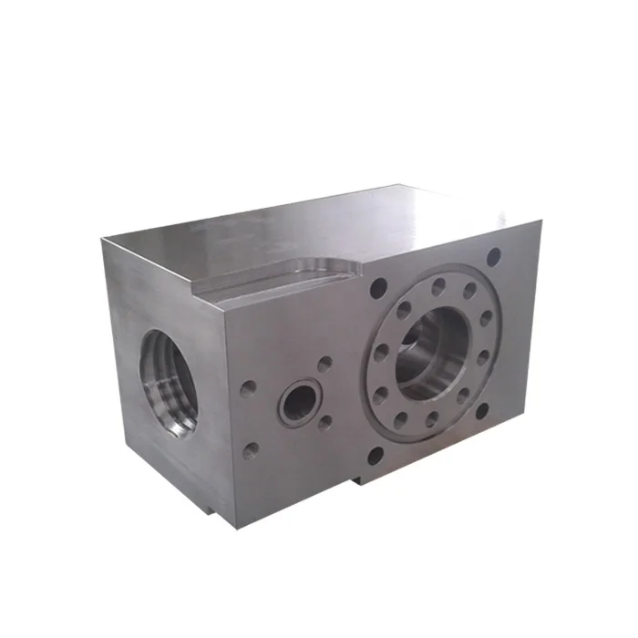
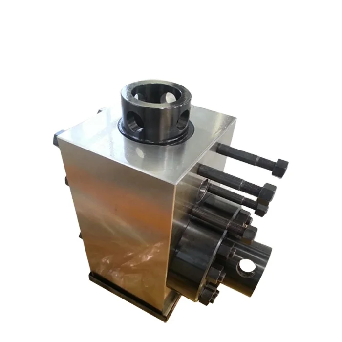
The modules 650 have a body 602 with a first bore 602 aand a second bore 602 b. A discharge valve assembly according to the present invention is in the first bore and a suction valve assembly according to the present invention is in the second bore. With a piston fluid is pumped into a chamber 652 of the module 650 via an inlet port 604 and is discharged from the module 650 into a discharge conduit 634 via an outlet port 606.
FIG. 2F shows the relative positions of two valve assemblies 100 a, 100 b(like the valve assembly 100) according to the present invention as they are present in a block of a mud pump module. The valve assemblies 100 a, 100 b(which may be any valve assemblies disclosed herein) are in bores 642, 643, respectively, in a block 644. The block 644 can be used in a system like that of FIG. 2A.
FIGS. 2G-2I show two valve assemblies 100 x, 100 y(like the valve assembly 100 a, FIG. 9A; may be any valve assembly according to the present invention) as they are disposed in a block B (shown in dotted line; may be any suitable block or body; including, but not limited to, the body 602 or block 644 referred to above) of a mud pump system. Fluid is sucked in by action of the suction valve assemblies 100 xthrough a suction inlet 400 and discharged by action of the discharge valve assembly 100 ythrough a discharge outlet 402. The fluid is received in a pumping chamber 404.
Fluid pumped from the chamber 404 can impact parts of the discharge valve 100 x. Optionally, an accumulator/dampener 410, positioned within the block B, is in fluid communication with the pumping chamber 404. The accumulator/dampener 410 reduces undesirable pulsations of fluid under pressure from the pumping chamber 404. Any suitable known accumulator/dampener may be used.
FIGS. 3A and 3B show a valve assembly 100 according to the present invention which can serve as a suction valve or a discharge valve for a mud pump system (e.g., but not limited to, the suction valve assembly 680 and the discharge valve assembly 630 described above; or the suction valve 100 xand the discharge valve 100 ydescribed above). FIG. 4 shows top portions of the valve assembly 100.
The poppet 114 is movable toward and away from a valve seat 160. The valve seat 160 has a channel 162 for fluid flow therethrough. The poppet 114 selectively closes off and opens up the channel 162 to fluid flow. Part of the channel 162 is sized and configured for the poppet 114. A surface 166 of the valve seat 160 is positioned to seal against the tapered of the surface 136 of the poppet 114. Optionally, there are no guide fingers projecting from the poppet 114 (although it is within the scope of the present invention to use them); and there are no arms or ribs across the valve seat (it is unobstructed) for receiving and stabilizing a rod, stem or neck projecting from a poppet; and there is no rod, neck or stem projecting from the poppet. Thus, flow through the channel 162 is unobstructed by such parts which are present in many prior valves.
A recess 168 around the valve seat 160 holds a seal 169. Part of the surface 136 of the poppet 114 sealingly abuts the seal 169 when the valve assembly is closed, preventing fluid flow. Thus dual sealing is achieved.
FIG. 6 shows one embodiment, a spring 120 a, of a spring 120. As compared to prior known spring designs, the spring 120 ahas a spring body with a smaller spring diameter, a, and with a higher spring force; but the wire diameter is relatively large, e.g. 0.22 inches, which results in the higher spring force. Use of an actuator like the actuator 130, FIG. 5, makes it possible to use a spring with the increased spring force (with the increased wire diameter). The overall diameter, b, of the spring 120 ais relatively smaller than prior springs because the spring 120 adoes not have to accommodate the relatively large necks of certain prior valve members. Certain prior mud pump valve springs reached a known resonant frequency (e.g. about 40 Hz to 43 Hz) creating poppet oscillations that resulted in an improperly seated poppet and in fluid pulsations transmitted downstream of a valve assembly. Due to its size and weight, the spring 120 ahas a higher natural frequency than those prior springs which resonate around 40 Hz and, thus, more force is required to resonate the spring 120 a. In certain aspects the spring 120 (or 120 a; or the spring 120 b, FIG. 7A) is sized and configured so its natural resonant frequency is about 25% higher than that of certain known springs (e.g., in one aspect 50 Hz vs 43 Hz). This reduces the chance of flow-induced resonance in the valve assembly with such a spring; provides better, more stable control of the valve assembly"s poppet; and provides more positive seating of the poppet against the valve seat.
FIGS. 8A and 8B illustrate steps in the operation of a valve assembly 100 (which has a spring 120 b, although any suitable spring may be used). As shown in FIG. 8A, air under pressure has not yet been applied within the hose 132 and the and the spring 120 burges the poppet 114 into sealing contact with the seal 169 and with the valve seat 160. The valve assembly 100 is closed to fluid flow therethrough. Fluid pressure also forces the poppet against the valve seat. On the discharge side of the valve seat at the beginning of the pumping/compression part of a cycle, the spring 120 band the fluid within a discharge manifold pushes the poppet 114 against the seat. This continues until the pressure within the discharge manifold drops below the pressure within the pumping cylinder and/or until the actuator 130 is commanded to open. On the suction side, the fluid within the pumping cylinder pushes the poppet 114 against the seat 160 again during the compression part and until the actuator 130 is commended to open the valve. When the “muscle” of the actuator 130 is not expanded, there is residual air trapped between the commanding valve and the actuator 130. The pressure of this trapped air is close to the pressure that existed in this line at the moment of exhausting the air and closing off the valve"s exhaust port. When the actuator is flexed, there is air at a pressure that is sufficient to open the valve, e.g. 110 psi. The actuator and air lines are filled in order to decrease the actuator"s response time—the time to respond to a commanding pressure. If the actuator is completely empty or, with, e.g. air at atmospheric pressure, it will take slightly longer for the actuator to respond, because when such a high pressure is applied the cavity would have to be filled with air first, then compress the air just introduced to a high enough pressure to barely stretch the hose 132 and only after that will the hose 132 change its length or respond to a commanding pressure.
As shown in FIG. 8B, air under pressure from an air supply 200 (with a proportional control valve 200 p) has been applied within the hose 132 causing it to expand and pulling the cable 128 away from the valve seat 160. In so doing, the poppet 114 is moved out of sealing contact with the seat 160 and the seal 169 of the valve seat 160 and the valve assembly is opened to fluid flow permitting fluid to flow into and out from a mud pump module housing the valve assembly.
It is advantageous that the poppet is part of the valve cartridge. During assembly, when the pump is assembled for the first time, it is much easier to have a preassembled valve cartridge and, without adjustments, to insert and bolt it in and have it immediately become functional. Moreover, in servicing the valve, it is much easier to extract the entire cartridge, versus bits, individual parts, and/or pieces. In certain current designs, a poppet/valve has a pseudo cartridge design in the sense that the valve has no restricting elements to keep it attached to the cartridge. In other words, the cartridge can be loosely put together prior to assembly and it can be inserted as a cartridge being secured to the body by bolts. However, if during this assembly process, or later on during servicing the valve, this cartridge is turned upside down, the valve itself can become loose and fall to the ground.
Often in such prior systems there is no element like a snap ring to secure the valve to the cartridge. It is also advantageous that the seal is part of the valve housing. It is easier to have the seat part of a block that can be preassembled to the pump and, later on, during a later step in manufacturing, to bolt on to it a subassembly like the valve cartridge.
In certain current designs, valves have two parallel surfaces. Often these surfaces form a seal that is part of conical bodies; i.e. the seal has a conical machined surface against which is pushed a poppet. The poppet"s sealing surface is also conical so that, at every instance, the seat"s and poppet"s sealing surfaces are parallel. During discharge, when the two bodies are separating and, thus, allowing the fluid to flow from the pumping chamber into the discharge manifold, the fluid is squeezed in between these flat surfaces. During this phase the fluid"s velocity can be greatly increased as it passes from a large cross section of the pumping chamber into a small one with parallel surfaces of the valve"s passage way. Moreover, because there is no controlling actuator, such a valve can open suddenly when the fluid"s pressure exerts onto the valve"s face a force slightly higher than that developed by the spring acting on the opposite face. As the fluid leaves at high velocity, it enters into a larger cross section that is the discharge manifold The high velocity and energy fluid acts almost like a piston in this case and pushes an adjacent block of fluid along the discharge line. This sudden move of a significant block of fluid can create a “bang” or a specifically loud noise almost like a pounding. This repeated banging/pounding can have detrimental effects on the drill line or other equipment.
In certain valve assemblies according to the present invention, the flat parallel surfaces are replaced by curved ones. Additionally, there is a controlling actuator that can open the valve before pressure in the pumping chamber reaches a value high enough to counteract the spring and, thus, to open the vale. Pressure at which the fluid leaves the pumping chamber is greatly reduced. Being formed in between two curved surfaces, the valve"s passage way flow characteristics do not impart a high velocity/energy to the fluid stream. Consequently, the fluid enters and leaves the discharge manifold and line respectively in a more dispersed manner. There is no “bang” as in certain previous valves because the fluid does not flow in discrete “blocks”.
The control system CS controls the air supply 200 and, thus, controls the valve assembly 100. This is in contrast to prior valves in which fluid flow opens and closes the valve. In one aspect, the control system controls the speed with which the parts move and thereby controls the speed of opening and of closing off the valve. Using appropriate software programming of programmable media in the control system, the control system controls an electro proportional valve control (e.g. the valve 200 p. FIG. 8B) that, in turn, controls the amount of air that enters or leaves the actuator 132. Consequently, the control system controls how fast, how long and how much the valve is opened. Gradual opening and closing is possible which reduces pressure pulsations. Each pump shaft (crankshaft) may have a speed sensor in communication with the control system (e.g. a sensor 521 s, FIG. 1). In systems with electric motors that drive the crankshaft(s), the motors are commanded through software in the control system and the same speed control signal can be broadcast to the control system. A dedicated speed sensor or a linear displacement transducer installed in every cylinder provides information for a closed loop control system (usable, e.g., to diagnose a pump in case of failure). With valve assemblies according to the present invention, the valves are not connected to the crankshaft.
The control system has programmable media, e.g. in a computer, computers, and/or PLC(s). In one aspect, the control system is preloaded with a program that includes a defining equation and a curve fitter. The defining equation is a function of pump shaft speed. The curve fitter compares the curve generated by the defining equation with an “ideal” curve desired to drive the valve The ideal curve usually represents the valve"s speed, or acceleration, or opening and/or, a different relevant parameter plotted versus time. The output from the control system drives a proportional valve, a valve that controls the actuator 130, e.g., in one aspect, supply air into a FESTO (TRADEMARK) “muscle”. Thus, the valve being actuated closely follows the preprogrammed curve/equation and the valve opens or closes at a certain velocity or acceleration, or that it opens at a certain rate over the duration of a pumping cycle. The opening or closing rate can be constant or variable. That is, the valve can start opening at a certain low rate followed by a higher rate followed by a different rate, and so on.
In one aspect, during a cycle the valve tends to follow a certain bell-shaped curve. Thus, the valve starts opening at a low rate followed at the very next instance by a slightly higher rate and in the next instance by an even higher rate and so on. All this is followed on the descending side of the curve by a lower rate followed by a slightly lower rate and so on until the valve closes. By introducing or expelling fluid into or from the pumping chamber at certain times the pump"s behavior is changed or the pump"s flow is measurable.
The mechanical equivalent of controlling a valve"s opening rate is a cam. The cam, through its profile, controls how fast and in what relationship relative to another element, e.g. a crankshaft, the valve will open or close. In other words, it controls the valve"s rate (displacement versus time). However, a cam"s profile can not be changed very easily because it is cut in metal. A practical method is to introduce a hydraulically actuated push rod or cam follower in between the cam and valve. Thus, the rate can change at will within a limited range. In the control strategy according to the present invention there is no piece of hardware/cam that limits the valve"s rate. Consequently, in the proposed actuation and control strategy, the desired curve can be changed on the fly as long as the controller, e.g. a computer or PLC, can accept/support it. Programmability makes this equivalent to an infinitely variable profile cam shaft and the pump"s output flow and vibration can be controlled. (An undesirable consequence of output flow in certain prior systems is component failure, e.g. due to cavitation.)
With the curved mating sealing surfaces of the valve seat and poppet, any contact results in an effective seal. Pressure fluctuations generated in or by prior art valves are reduced or eliminated and valve control reduces pressure fluctuation in the discharge line during pump operation.
Systems according to the present invention provide a fail safe mode. If a valve assembly according to the present invention that is inserted fails, then, for safety reasons, the pump continues working at either reduced or normal parameters until it is safe to stop it for service. In systems according to the present invention, if the actuator fails, e.g. if the muscle fails, it breaks or bursts, the valve will operate unrestricted (e.g. as a current known design valve). Thus, the pump can continue working at almost the same parameters until it is safe to stop it.
FIGS. 9A and 9B show a valve assembly 100 a, like the valve assembly 100 (like numerals indicate like parts) with a spring 120 band a poppet 114 a. The poppet 114 ahas a nose 114 nprojecting from a poppet body 114 b. The nose 114 nprojects into the flow channel 162 of the valve seat 160. In certain aspects, in systems according to the present invention the surface on the valve seat becomes, advantageously, more elastic. In a seal, two surfaces or edges are pushed against each other by a force. This acting force can be perpendicular to or at an arbitrary angle relative to the sealing surfaces. In systems according to the present invention the sealing bodies are the rubber seal and the poppet in one instance and, the seat itself and the poppet in a second instance. During a valve closing cycle, the first seal occurs in between a rubber O-ring and poppet. The acting force is axial relative to the poppet, but it is at an angle relative to the edge of contact between the two curved surfaces of the O-ring and poppet respectively. When the two bodies come into contact, at the point of contact, the vector components of this acting force are a normal to curved surfaces component and a tangential to curve components. This tangential component will stretch the rubber (the over hanging part of it) instead of purely compressing it. With the rubber O-ring being surrounded/supported by the seat"s rigid body, the rubber will take a very high force in compression as the normal-to-curved surfaces vector component. The rubber becomes difficult to compress when it is surrounded by a rigid wall. Thus a mechanical maze is formed and, thus, the fluid encounters a high flow resistance. There is a sequence of high pressure (inside the pumping chamber), followed by a no flow area (where the rubber O-ring contacts the poppet), followed by a low pressure area (right after the rubber seal) and finally, followed by a no flow area at a contact between the poppet and the seat. Also, the shape of the deformed rubber O-ring at the leading edge toward the impinging fluid does not allow the fluid to enter in between the poppet and seal.
A valve assembly according to the present invention with a poppet like the poppet 114 aprovides uniform and stable poppet positioning and movement. FIG. 9D illustrates a velocity profile of incoming fluid E flowing around a poppet 114 a. Two rings A of high velocity fluid flow surround the poppet 114 a. The rings A are continuously and uniformly distributed all around the poppet 114 a, creating elastic cushions B that surround and stabilize the poppet 114 a, e.g. in the event of a disturbing force acting in a direction other than in an axial direction. A reverse fluid flow C (part of the flow E which has changed direction) acting on a back side of the poppet 114 atends to push the poppet 114 ainto the closed position shown against the incoming flow E and against the two elastic cushions B. The uniformity and distribution of the flow C also facilitate the maintenance of the poppet 114 ain a stable attitude.
FIG. 9E illustrates pressure distribution of an incoming flow E around the poppet 114 a. High pressure elastic fluid cushions D that surround and stabilize the poppet 114 a. The incoming flow E has a smooth transition around the nose 114 mof the poppet 114 aand the ensuing flow sticks (binds to or tends to flow along adjacent a curved surface) to the curved poppet surfaces. A reverse flow C will not suffer a sudden change in direction, but a gradual one (e.g. as illustrated by the curved arrows W of the flow C at the back of the poppet). In certain prior valves such a flow hits a poppet"s back surface and flows at or near a ninety degree angle to the back of the poppet. Wobbling of the poppet 114 ais reduced or eliminated and it will maintain a stable position with its vertical axis concentric with that of the tubular within which it is positioned.
In contrast, in certain prior art valve assemblies with typical plain rounded-head poppets, there are sudden ninety degree changes of fluid flow direction on both faces of the poppets. Sudden changes in the direction of fluid flow, as well as turbulence behind the poppet, can generate some flow-induced destabilizing forces. Also, with such typical plain rounded-head poppets with relatively large flat end surfaces, two areas of low pressure (vacuum or close to vacuum) are developed around sharp edges of the poppets. These areas are within and surrounded by high pressure. This pressure distribution can lead to cavitation and unstable attitude in flow. Also, discrete veins of flow can occur where these low pressure areas take place. Consequently, because of a non-uniform distribution around the body, the poppets will have a precession motion. This effect is amplified by the geometrical dimensions of the poppets. Non-uniform flow distribution results on the poppets back sides.
The present invention, therefore, provides in at least some embodiments, a system for pumping a drilling fluid mixture, the drilling fluid mixture containing drilling fluid and solids, the system including: a pump apparatus; the pumping apparatus having a body with an inlet and an outlet; a suction valve in the body for selectively controlling flow of the drilling fluid mixture in through the inlet; a discharge valve in the body for selectively controlling flow of the drilling fluid mixture out through the outlet; each of the suction valve and the discharge valve having a seat with a curved valve seat surface and a valve member with a curved member surface, part of the valve member movable to seat the curved member surface against the curved valve seat surface to prevent the flow of the drilling fluid mixture past the valve seat. Such a system according to the present invention may have one or some (in any possible combination) of the following: a seal recess in the curved valve seat of each of the suction valve and the discharge valve, a seal positioned in each seal recess so that resonating of the seal is inhibited, each valve member movable to seat against a corresponding seal; wherein each valve member has a range of freedom of movement for effecting seating against an adjacent corresponding curved valve seat surface (and, in certain aspects, against a seal in the valve seat), the freedom of movement including the ability to move not just toward and away from the valve seat but at an angle thereto; wherein each valve member has a spring urging the valve member against the curved valve seat surface; wherein the spring has a spring body with a first end and a second end, the first end in contact with the valve member, the first end tapering from the spring body; each valve having a cartridge stem positioned with respect to the valve member, and a valve actuator within the cartridge stem for selectively moving the valve member; wherein the valve actuator is interconnected with the valve member via a cable; the valve actuator includes a selectively expandable hose for moving the valve member; an air supply for supplying air to the valve actuator, and a control system for controlling the air supply to selectively open and close the valve; a ball movably mounted within each valve member, the cable connected to the ball and to the valve actuator, the valve member movable with respect to the ball; each valve member has a rounded nose and a curved tapered outer surface so that fluid flow contacting the nose and curved tapered outer surface forms stabilizing fluid cushions around the valve member; each valve member has a back surface, a portion of the fluid flow onto the nose and curved outer surface gradually changes direction on the back surface; wherein the seat has a flow channel adjacent the curved valve seat and the valve member is movable to close off flow through the flow channel and wherein the flow channel is unobstructed; and/or wherein each valve member has a spring urging the valve member against the curved valve seat surface, each spring having a top end with at least one curved spring projection, a spring mount within the valve member, the at least one spring projection movably connected to the spring mount to facilitate freedom of movement of the valve member with respect to the curved valve seat surface and/or a dampener within the body for inhibiting pulsations of fluid pumped from the pump apparatus.
The present invention provides systems for pumping a drilling fluid mixture, the drilling fluid mixture containing drilling fluid and solids, the systems having: a pump apparatus, the pumping apparatus having a body with an inlet and an outlet, a suction valve in the body for selectively controlling flow of the drilling fluid mixture in through the inlet, a discharge valve in the body for selectively controlling flow of the drilling fluid mixture out through the outlet, each of the suction valve and the discharge valve having a seat with a curved valve seat surface and a valve member with a curved member surface, part of the valve member movable to seat the curved member surface against the curved valve seat surface to prevent the flow of the drilling fluid mixture past the valve seat, a seal recess in the curved valve seat surface of each of the suction valve and the discharge valve, a seal positioned in each seal recess so that resonating of the seal is inhibited, each valve member movable to seat against a corresponding seal, each valve having a cartridge stem positioned with respect to the valve member, and a valve actuator within the cartridge stem for selectively moving the valve member.
The present invention provides a method for pumping fluid, the method including: sucking fluid into an inlet of a pumping apparatus of a system, the system comprising a pump apparatus, the pumping apparatus having a body with an inlet and an outlet, a suction valve in the body for selectively controlling flow of the drilling fluid mixture in through the inlet, a discharge valve in the body for selectively controlling flow of the drilling fluid mixture out through the outlet, each of the suction valve and the discharge valve having a curved valve seat surface and a valve member with a curved member surface, part of the valve member movable to seat the curved member surface against the curved valve seat surface to prevent the flow of the drilling fluid mixture past the valve seat; and with the pump apparatus, pumping fluid into the inlet and then out the outlet. The present invention provides wherein such a system, in certain aspects, that has a seal recess in the curved valve seat of each of the suction valve and the discharge valve, a seal positioned in each seal recess so that resonating of the seal is inhibited, each valve member movable to seat against a corresponding seal, the method further including seating each valve member surface against a corresponding seal; and/or wherein each valve has a cartridge stem positioned with respect to the valve member, and each valve has a valve actuator within the cartridge stem for selectively moving the valve member, the method further including actuating each of the suction valve and the discharge valve with the valve actuator.
The present invention provides a method for pumping fluid, the method including: sucking fluid into an inlet of a pumping apparatus of a system, the system having a pump apparatus, the pumping apparatus having a body with an inlet and an outlet, a suction valve in the body for selectively controlling flow of the drilling fluid mixture in through the inlet, a discharge valve in the body for selectively controlling flow of the drilling fluid mixture out through the outlet, each of the suction valve and the discharge valve having a curved valve seat surface and a valve member with a curved member surface, part of the valve member movable to seat the curved member surface against the curved valve seat surface to prevent the flow of the drilling fluid mixture past the valve seat, wherein each valve member has a range of freedom of movement for effecting seating against an adjacent corresponding curved valve seat surface; with the pump apparatus, pumping fluid into the inlet and then out the outlet; controlling fluid flow in through the inlet with the suction valve; and controlling fluid flow out the outlet with the discharge valve.
The present invention provides a method for pumping fluid, the method including: sucking fluid into an inlet of a pumping apparatus of a system, the system including a pump apparatus, the pumping apparatus having a body with an inlet and an outlet, a suction valve in the b


 8613371530291