
mud pump for 100 feet wells free sample

Typically, well pumps can be broken down into two categories: jet pumps and submersible pumps. Each design is built to fit the needs of various well sizes and conditions.
Most shallow well pumps are found in wells that are less than 25 feet deep and in areas with a high water table. These pumps have few running parts and require little maintenance.
This type of pump is located above the ground, typically just inside the well house, and generates high pressure to pull the water from the well and into the home using an inlet pipe. A tank or well booster pump is recommended to accompany this type of well pump to increase water pressure to the home.
Unlike its shallow counterpart, a deep well jet pump is located within the well, though its motor stays in the well house. This pump uses two pipes: one for drawing water out of the well and another for directing the water to the home. Deep well jet pumps are typically used in wells that are 110 feet deep.
A deep well submersible pump sits at the bottom of the well directly in the water. Using its motor, the pump draws water from the bottom and pushes it out of the well into your home’s water lines. These pumps can be used in wells up to 300 feet deep. The pumps work similar to sump pumps, which draw water and pump it out.
Although professional well pump replacement comes with high pump installation costs, you may have no choice but to call a professional depending on the well pump you have. Certain pumps, like deep well submersible pumps, require special equipment to get them out without damaging components or wiring. In addition to the fragility of the well’s components, removing a well pump can be very labor intensive, with some pumps weighing more than 100 pounds.
Even if you’re considering replacing your well pump on your own, call a plumber to confirm that the well pump is the issue with your system before removing it. This will prevent any unneeded work or unintentional damage to your well system.
Use the tool below to find a well service contractor who can diagnose your well pump problem and help you determine whether or not you can replace it yourself:

This website is using a security service to protect itself from online attacks. The action you just performed triggered the security solution. There are several actions that could trigger this block including submitting a certain word or phrase, a SQL command or malformed data.

When choosing a size and type of mud pump for your drilling project, there are several factors to consider. These would include not only cost and size of pump that best fits your drilling rig, but also the diameter, depth and hole conditions you are drilling through. I know that this sounds like a lot to consider, but if you are set up the right way before the job starts, you will thank me later.
Recommended practice is to maintain a minimum of 100 to 150 feet per minute of uphole velocity for drill cuttings. Larger diameter wells for irrigation, agriculture or municipalities may violate this rule, because it may not be economically feasible to pump this much mud for the job. Uphole velocity is determined by the flow rate of the mud system, diameter of the borehole and the diameter of the drill pipe. There are many tools, including handbooks, rule of thumb, slide rule calculators and now apps on your handheld device, to calculate velocity. It is always good to remember the time it takes to get the cuttings off the bottom of the well. If you are drilling at 200 feet, then a 100-foot-per-minute velocity means that it would take two minutes to get the cuttings out of the hole. This is always a good reminder of what you are drilling through and how long ago it was that you drilled it. Ground conditions and rock formations are ever changing as you go deeper. Wouldn’t it be nice if they all remained the same?
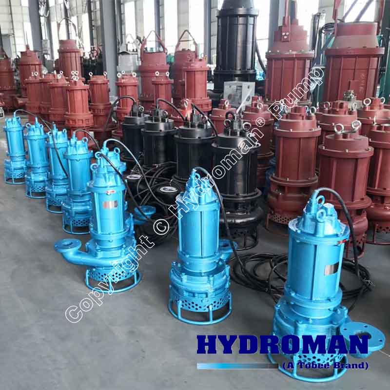
Centrifugal-style mud pumps are very popular in our industry due to their size and weight, as well as flow rate capacity for an affordable price. There are many models and brands out there, and most of them are very good value. How does a centrifugal mud pump work? The rotation of the impeller accelerates the fluid into the volute or diffuser chamber. The added energy from the acceleration increases the velocity and pressure of the fluid. These pumps are known to be very inefficient. This means that it takes more energy to increase the flow and pressure of the fluid when compared to a piston-style pump. However, you have a significant advantage in flow rates from a centrifugal pump versus a piston pump. If you are drilling deeper wells with heavier cuttings, you will be forced at some point to use a piston-style mud pump. They have much higher efficiencies in transferring the input energy into flow and pressure, therefore resulting in much higher pressure capabilities.
Piston-style mud pumps utilize a piston or plunger that travels back and forth in a chamber known as a cylinder. These pumps are also called “positive displacement” pumps because they literally push the fluid forward. This fluid builds up pressure and forces a spring-loaded valve to open and allow the fluid to escape into the discharge piping of the pump and then down the borehole. Since the expansion process is much smaller (almost insignificant) compared to a centrifugal pump, there is much lower energy loss. Plunger-style pumps can develop upwards of 15,000 psi for well treatments and hydraulic fracturing. Centrifugal pumps, in comparison, usually operate below 300 psi. If you are comparing most drilling pumps, centrifugal pumps operate from 60 to 125 psi and piston pumps operate around 150 to 300 psi. There are many exceptions and special applications for drilling, but these numbers should cover 80 percent of all equipment operating out there.
The restriction of putting a piston-style mud pump onto drilling rigs has always been the physical size and weight to provide adequate flow and pressure to your drilling fluid. Because of this, the industry needed a new solution to this age-old issue.
Enter Cory Miller of Centerline Manufacturing, who I recently recommended for recognition by the National Ground Water Association (NGWA) for significant contributions to the industry.
As the senior design engineer for Ingersoll-Rand’s Deephole Drilling Business Unit, I had the distinct pleasure of working with him and incorporating his Centerline Mud Pump into our drilling rig platforms.
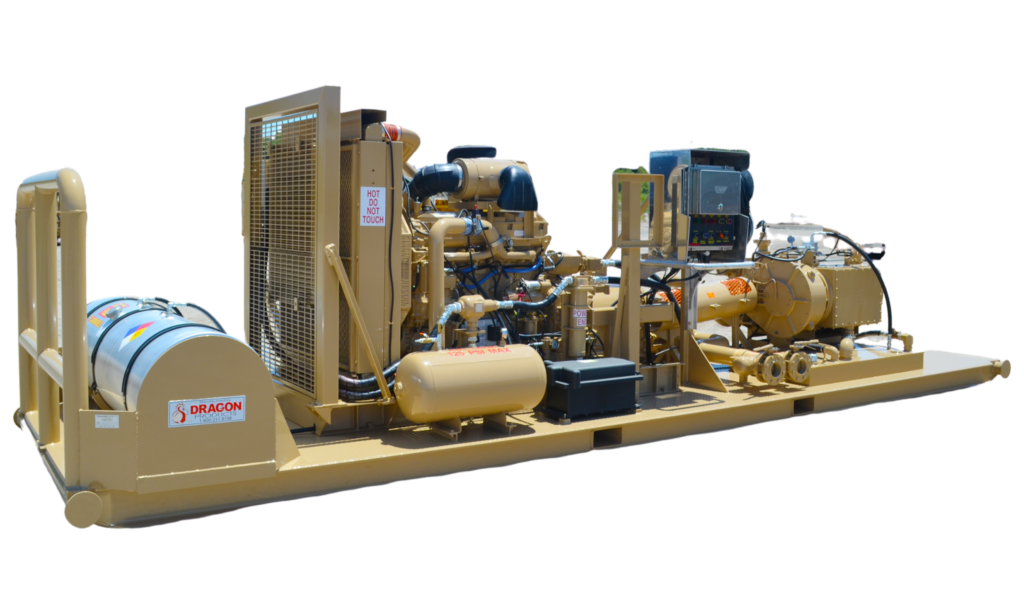
In the late ’90s — and perhaps even earlier — Ingersoll-Rand had tried several times to develop a hydraulic-driven mud pump that would last an acceptable life- and duty-cycle for a well drilling contractor. With all of our resources and design wisdom, we were unable to solve this problem. Not only did Miller provide a solution, thus saving the size and weight of a typical gear-driven mud pump, he also provided a new offering — a mono-cylinder mud pump. This double-acting piston pump provided as much mud flow and pressure as a standard 5 X 6 duplex pump with incredible size and weight savings.
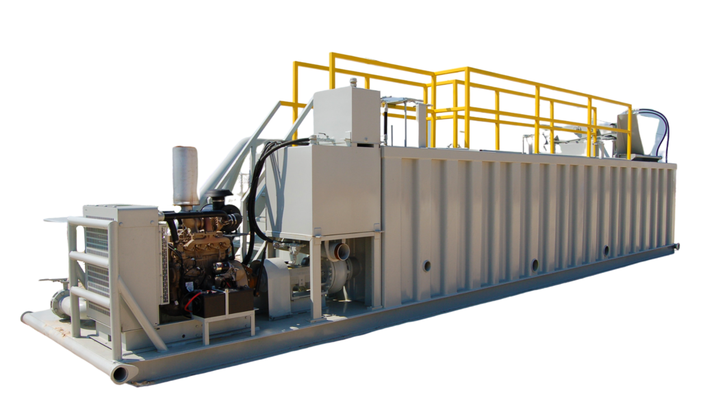
The true innovation was providing the well driller a solution for their mud pump requirements that was the right size and weight to integrate into both existing and new drilling rigs. Regardless of drill rig manufacturer and hydraulic system design, Centerline has provided a mud pump integration on hundreds of customer’s drilling rigs. Both mono-cylinder and duplex-cylinder pumps can fit nicely on the deck, across the frame or even be configured for under-deck mounting. This would not be possible with conventional mud pump designs.
The second generation design for the Centerline Mud Pump is expected later this year, and I believe it will be a true game changer for this industry. It also will open up the application to many other industries that require a heavier-duty cycle for a piston pump application.

However, the electrical and motor cooling requirements are certainly different with voltage drop to the motor and various other factors becoming much more important. In Part 2 of this three-part series on the design of a submersible pump we will design our pump end using the hydraulic design data to fit the same sample application we previously used for a vertical turbine pump.
Using our example installation in previous columns of The Water Works, we have successfully designed a sample water pumping installation for a vertical turbine pump with the following conditions:
Now that we have completed the determination of the required pump capacities and operating head, the first step in actually selecting a submersible pump end is to estimate the target horsepower required for the design conditions. From Part 1 (WWJ, January 2017):
From the above brake horsepower (BHP) estimates, it is apparent there will be a wide disparity of required horsepower (almost 30 BHP) between the two operating points. Generally, an application that requires two operating points so far apart requires strong consideration of either using a variable frequency drive (VFD) to use the affinity laws to lower the pump and motor speed for the alternate condition, an inline control valve to regulate outlet pressure and pump discharge, or a pump with an extremely flat head-capacity (H-Q) curve.
In our example, the use of a VFD has previously been determined to be the most cost effective solution, although an inline control valve could also have been used. However, it is highly unlikely the desired horsepower of 14.5 BHP at the alternate COS would have been met as the majority of submersible units have steep operating curves, owing to multiple stages plus the pump speed of 3450 RPM.
The final option, use of a flat curve pump, would also be unlikely as a preferred choice. Again, this is due to the pump’s rotation speed and number of pump stages required, except for the possible use of a 10-inch or 12-inch-diameter pump, which would require fewer stages than a smaller unit.
Although the hydraulic design is primarily vested in the pump’s capacity and head, the bowl diameter is also a critical factor. With a submersible pump, the bowl diameter is generally dictated by two primary conditions: the required pumping rate needed (in gallons per minute) and the limiting diameter of the well casing or wet well the bowl will be placed into (the maximum bowl outer diameter [O.D.]).
Table 1 cites the general maximum and minimum flow rates (including speed reduced minimum flows) for various bowl diameters at their respective best efficiency point (BEP) from various manufacturers for 3520/3450 RPM (3600 RPM synchronous speed) and 1760/1725 RPM (1800 RPM synchronous speed) rotational speeds.
The maximum rated capacity for each bowl diameter and speed are based on the typically highest BEP from various manufacturers, while the minimum flow for each bowl diameter and 3600 RPM speed represents an approximate maximum pump and motor speed reduction of 40% from the practical BEP at the lowest rated flow rate for each diameter and speed.
This would approximate correction of the performance of a submersible pump and motor when used on a VFD or when used with a control valve to maintain a minimum motor speed of 36 hertz (~2100 RPM) to maintain proper motor cooling and bearing lubrication, well above the manufacturer’s typical minimum of 30 hertz (~1750 RPM).
Vertical turbine pumps (VTPs) do not generally operate with the same flow range limitations as submersible pumps and motors. Therefore, the range of allowable flow rates with a VTP is often greater than that with a comparable submersible unit. The vast majority of 6-inch and most 8-inch-diameter submersible pump motors below 100 HP operate at a two-pole speed, or 3600 RPM. Therefore, this example pump selection should also be conducted using that same speed.
Given the knowledge of the primary and secondary (alternate) design capacities (500 GPM and 156 GPM) and the well diameter (12 inches) creates a fairly easy determination of the bowl diameter. From Table 1 it is apparent either a 6-, 7-, 8-, 9-, or even a 10-inch-diameter bowl assembly at 3450 RPM will likely work for this application with a 6-inch-diameter bowl at the extreme end of its practical and efficient flow range for 500 GPM.
The minimum recommended flow for a 10-inch-diameter bowl is also above the BEP for the low flow of 156 GPM and will most likely only require two or three stages to produce the needed head, which will result in a flatter total head curve. This is generally not as desirable for use with a VFD and compromises the pump efficiency and optimum clearance inside a 12-inch-diameter well by using a 10-inch-diameter bowl. This tends to limit the best overall selection to a 7-, 8-, or 9-inch-diameter bowl.
Building a unit through an analysis of a per-stage performance of individual stages (Figure 1), as with a VTP, and then dividing the total head required by the head per stage to determine the number of stages and horsepower needed to create an assembled pump.
Evaluating a manufacturer or supplier’s preselected and preassembled units and then selecting a pump that comes closest to the required flow and head (Figure 2).
When using a single-stage performance curve to evaluate a potential submersible pump, always be cognizant multi-stage pumps almost always display a higher efficiency at the same operating point, impeller trim, and capacity than a single-stage unit, so an efficiency correction may be needed.
For example, the single-stage bowl assembly shown in Figure 1 is the same bowl assembly with the same impeller trim (4.875 inches) and nominal speed (3600 RPM) as the 4-stage bowl assembly in Figure 2. However, the efficiency is three points higher (77.9% vs. 74.9%) for the 4-stage bowl. This relationship holds true for both VTPs and submersible pumps.
Usually, if any correction is required for multiple stages, this is generally indicated on the pump curve itself. In many cases this type of unit is further classified by the bowl’s BEP design flow and/or motor horsepower, especially when stainless steel impellers are used. Stainless steel impellers are not as easy to trim. Therefore, knowledge of the well diameter and the approximate required horsepower will often provide a shortcut to a pump selection.
For our example, 43.77 of estimated HP translates to the probable need for a 50 HP motor. This could provide the information required to select a preassembled submersible pump with a rating of 500 GPM and a 50 HP motor. This procedure is often shown on pump selection data sheets or curves with nomenclature to indicate the bowl diameter first, followed by the pump’s rated capacity or relative rating, the number of stages, or the motor horsepower.
For example, a specific manufacturer may use a model number such as 7TLC, 7CHE, 8RJO, or 8M23. The first number (7 or 8) usually signifies the bowl’s outer (nominal) diameter. The second and/or third letter (TL, CH, RJ, or M) may designate the manufacturer’s bowl capacity or head rating, such as L for low, M for medium, or H for high. The final letter or number often describes whether the impeller is an open (using an O) or enclosed (E or C) impeller. The use of a specific number (as in 23 for 230 GPM) may indicate the bowl’s rated capacity at its BEP. In some cases, “S” is inserted into the model number to signify the unit is a submersible pump.
Finally, the number of stages and the horsepower rating is often applied to the end or sometimes as part of the model number. A complete model number for an assembled submersible pump unit, for example, may be an 8SHHE-7-100, to signify an 8-inch nominal bowl diameter submersible pump, with a high capacity and head rated enclosed impeller, equipped with seven stages, and a 100 HP rated horsepower motor. In all cases, you should verify the breakdown of a specific model number with the manufacturer as many pumps do not follow these criteria.
Occasionally, I receive a request from someone to design a submersible pump using a semi-open impeller. Although I have used this type of impeller numerous times on VTPs, I do not routinely use them on subs for several reasons.
First, since they are locked onto the pump shaft and often situated several hundred feet down a well, they cannot be adjusted to regain performance or efficiency without pulling from the well. Secondly, although semi-open impellers are often a few points higher in efficiency, they usually display more axial and radial thrust than enclosed impellers, making them undesirable for use on the lower thrust rated submersible motor.
Finally, designing an application using semi-open impellers is at best an estimation since the pump’s performance and horsepower draw is primarily a factor of the impeller’s proper running clearance from the bowl. Any variation to this clearance from the manufacturer’s published curve data will adversely impact the performance by underperforming, overperforming, over possibly overloading the motor.
The seven submersible pump ends in Table 2 represent only a fraction of those available for the primary conditions of service. However, these potential selections nonetheless represent a cross-section of the typical bowl diameters and number of stages to consider for this application.
The final determination of the selected pump must weigh several factors. Some are universal while others may be site or locality specific. And since it is fairly obvious all the selected bowls will fit inside the 12-inch well casing, this initial factor can be ignored.
The next selection criteria I generally examine is the BHP requirement and pump efficiency at the specific operating condition that will be subject to the highest use. In our example, even though the bowl assembly has been designed for a primary design condition of 500 GPM, in actuality the pump will usually operate somewhere between the two design points with the alternate COS (156 GPM) in service much more than the primary COS. The three units with the lowest BHP requirement at the alternate design condition in the table are pumps R-1, F-1, and M-1.
My next criteria, particularly since the efficiency at the primary COS is close for all units, is to evaluate the operating speed at the alternate COS. This is more important to the success of the installation than one might imagine, particularly when a VFD will be used for motor control. Most motor (and some pump) manufacturers dictate the motor speed shall not fall below 50% speed (30 hertz, or ~1750 RPM). This is to provide adequate bearing lubrication in the motor as well as maintain enough velocity past the motor for cooling. As previously stated, when feasible, I prefer to design an installation so the pump and motor will not exhibit a minimum speed below 40% of the motor’s rated speed or about 2050-2100 RPM.
Tempered with this fact, however, is the knowledge the motor must be permitted to operate at a low enough speed to facilitate a reasonable VFD operating range and proper control settings. Experience has taught me this factor works best for a multi-stage submersible unit when using a shutdown speed between 70%-90% of full load (FL) speed—a range of 75%-85% of FL motor shutdown motor speed often works the best. Obviously, all these criteria must be ascertained after a full evaluation of the pump curve (flat vs. steep) and HP at the minimum speed.
From an examination of the pumps in Table 2, it is evident all the sample pumps fulfill these desires, with pumps G-1, R-1, L-1, G-2, and F-1 fitting the best at the reduced flow of 156 GPM along with a reduced speed range between 75%-85% of FL speed.
Finally, when cost is a factor, weighing the individual options for the lowest initial and operating cost is often conducted. For this final evaluation, pumps R-1 and F-1 were both good choices, although my ultimate selection was for pump R-1 as the runout capacity (Q = 575 GPM) was lower than F-1. The BEP for the R-1 pump was also slightly to the left of the primary design point which helps to retain higher operating efficiencies at lower speeds, plus the pump was represented locally and replacement parts were more readily available.
The runout capacity of ~575 GPM is an important selection criteria for this example to avoid excessive well overdraft, especially since flows above 500 GPM will be served from a supplementary source. See Figure 3 and Figure 4 for full speed and variable speed curves for pump R-1, a 7-inch × 3-stage bowl assembly.
Now that the pump end has been selected, we generally examine any special construction or metallurgy required for the pump end. If sand or abrasives were a concern, bowl wear rings might be warranted. If the bowl’s upper stages were exposed to excessive high pressures, O-rings or gaskets may be indicated to prevent inter-stage leakage. Since most 6- and 8-inch bowl assemblies are constructed using threaded construction between stages, this would usually not be a concern unless a 10-inch or larger diameter bowl was selected and only then with pressures in excess of the manufacturer’s pressure rating.
Next, static or dynamic balancing of the impellers should be considered. On one side, this pump uses a stock pump with only three stages and fairly small diameter (4.875 inches) impellers, plus we plan to use a 7-inch-diameter bowl inside a 12-inch well casing, so balancing of the impellers is probably not needed. However, the added cost for balancing just three impellers does not generally represent a huge added cost to the bowl assembly. So if there is any concern regarding the well’s alignment, this may be a desirable option.
Finally, many firms feel all larger capacity units should be factory tested to verify performance. Although I often require factory testing for expensive or large or deep well pumping units, submersible and vertical turbine, I rarely require or recommend factory testing on smaller (<10 inches) wet ends for various reasons.
Besides the added cost (which can actually cost more than the pump itself) and the associated time delay, experience has shown conducting factory testing on smaller diameter, multi-stage pumps does not generally result in any true power savings or added assurance to the owner, especially since the selection curves from the majority of pump manufacturers have repeatedly been shown to be accurate for capacity, head, and horsepower. Also note the majority of submersible pump models between 6 and 12 inches have been tested by their manufacturer during development.
Remember, any of the above concerns will usually result in not only added cost but a delay in constructing and shipping the unit, so consider these carefully. For our example, none of these concerns are present, so the final factor would be the pump setting and drop pipe size.
The riser drop pipe and check valve sizes depend on various factors: the desired minimum and maximum uphole velocities (critical when using a VFD); friction losses; pipe cost; well and drop cable clearance; and adequate space for any additional elements in the well/pipe annulus—sounding tubes, well or water level measurement devices, future chemical treatments. For our example installation, the pump will operate within a range of 156 GPM minimum, up to 500 GPM maximum.
Figure 5b shows flow ranges for various pipe sizes, and indicates a desired flow range of 160-700 GPM for 5-inch drop pipe. These values will maintain a minimum uphole velocity of ~2.5 feet per second (FPS) at 160 GPM to transfer any heavier solids from the well to prevent settlement onto the pump, with a maximum uphole velocity of 10 FPS at 700 GPM as an upper economic sizing. Figure 5b shows friction loss for new 5-inch steel drop pipe at 500 GPM is 4.16 feet per 100 feet of pipe with a velocity of 8.02 FPS.
Figure 6 and Figure 7 are included for those who use either PVC or flexible hose as drop pipe. We will finalize the friction loss calculation upon determining the pump setting.
The desired pump setting is truly a case-by-case determination that must be performed with full knowledge of the well casing diameter and depth, well screen upper termination depth, the reliable pumping water level (PWL), sand or abrasives pumping potential, and a reserve (safety) factor for unusual well drawdown or seasonal drafts.
Typically, I like to plan deep well installations to maintain a minimum of 10 feet of submergence over the top of the pump, not the suction or inlet, at the maximum projected pump capacity. For our example, this translates to a minimum pump setting of 110 feet (~100 feet PWL at 515 GPM + 10 feet of submergence).
In cases such as this example, when more depth is available I prefer to set the pump at least 20 feet deeper in the well to compensate for any future well decline or seasonal shifts. So, I will plan for 150 feet of drop pipe. This results in the use of seven lengths (147 feet at 21 feet per length) plus a 3-foot length for the upper well seal to provide an easy-to-remember figure for future reference.
The total friction loss would therefore be 4.16 feet/c × 1.5 (for 150 feet) = 6.24 feet + 1.60 feet for the riser check valve and miscellaneous loss = 7.84 feet total, well under our original estimate of 10 feet. The riser check valve should be placed between 5 to 20 feet above the pump, with 10 to 11 feet (the first full 21-foot joint above the pump cut and threaded in half), my usual location. This places the check valve at a sufficient distance above the pump to allow for the vertical movement of any entrapped air or vapor from the pump to the check valve and avoid air locking of the pump. It also provides two shorter pipe lengths to enable easy installation of the pump/motor and the well seal.
Also, remember in our example and any installation with a VFD, the riser check valve should be designed for continuous operation on a VFD to prevent possible valve chatter and premature failure. The proposed finished installation, along with alternate wellhead completion techniques, are shown in Figure 8.
This concludes Part 2 of the three-part series on sizing of submersible pumps for municipal, industrial, and commercial water supply. In Part 3, we will conclude with a detailed discussion of sizing and installing the submersible motor and drop cable, plus some of the pitfalls and issues associated with using this type of pump and motor.
To help meet your professional needs, this column covers skills and competencies found in DACUM charts for drillers and pump installers. PI refers to the pumps chart. The letter and number immediately following is the skill on the chart covered by the column. This column covers: PIC-5, PIC-6, PIC-10, PID-4, PIE-8, PIE-9, PIE-13, PIE-14 More information on DACUM and the charts are available at www.NGWA.org/Certification and click on “Exam Information.”
We have a huge air compressor on the rig that blows air down the drill stem. The air comes back up the hole with enough force to move all cuttings up and out of the hole. If the well is producing water, the water will come too. Most of the time, we are actually pumping water into the air stream already, and we are really looking for an increase in the water. If we think we have hit water, we can turn off our water injection pump and check the flow of water with the air compressor alone.
There is no definite answer to this question. We are estimating the flow based on what we see flowing from the well. Sometimes, the air pressure in the well can “hold back” on the flow, causing us to underestimate the production capacity. To overcome this, we can release the air pressure for a few minutes, and then reapply it after the well has built up a large volume. We then would see the volume of water that the well produced after several minutes. Then with simple math, we can calculate the production capacity. But it is also important to understand that the well production can also vary over time. So the well may produce more or less water in the future than it does today.
We are not only looking for water. We are mainly looking for the rock that produces water. The depth of each layer of rock depends greatly on the location and elevation of the drill site. The formations are relatively flat below the surface. However, they may not be level. We use a gps to tell us the elevation of your drill site and we survey the area wells that we have drilled and compare their elevations. From this, we can estimate the depth that your well will need to be. However, we have found out on many occasions, that when God laid the foundations of the earth, He followed no rules. It is not uncommon to see formations rise or fall several hundred feet in a mile. For instance, we drill in one subdivision where the depth to the lower trinity is 760′ on one side of the road, and 840′ on the other. We can never be sure about the depth of your well until we actually drill.
This website is using a security service to protect itself from online attacks. The action you just performed triggered the security solution. There are several actions that could trigger this block including submitting a certain word or phrase, a SQL command or malformed data.

This website is using a security service to protect itself from online attacks. The action you just performed triggered the security solution. There are several actions that could trigger this block including submitting a certain word or phrase, a SQL command or malformed data.
dear whoever wrote this, i did not actually read this 1100+ page book. i saw a picture of a dog listening to an old timey record player and i vibed with it really hard. he is super adorable. hes onpage 1056 or something like that. beyond that i really dont know what this was about. fur trapping, maybe? i dont know, nor do i care. i only found this "book" because i googled "how many eggs do i have to eat before i can regrow my limbs? please and thank you." ANYWAYS, if youre reading i wanna say hello, and ummmm, how are you and i hope you are having a lovely day. :)


 8613371530291