
mud pump for dug well in stock
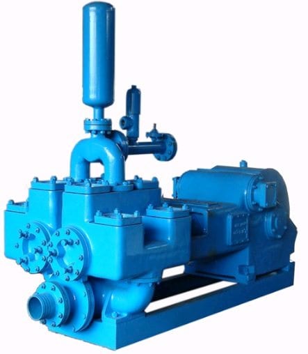
A mud pump is a reciprocating piston/plunger pump designed to circulate drilling fluid under high pressure (up to 7,500 psi (52,000 kPa)) down the drill string and back up the annulus. A duplex mud pump is an important part of the equipment used for oil well drilling.
Duplex mud pumps (two piston/plungers) have generally been replaced by the triplex pump, but are still common in developing countries. Two later developments are the hex pump with six vertical pistons/plungers, and various quintuplex’s with five horizontal piston/plungers. The advantages that Duplex mud pumps have over convention triplex pumps is a lower mud noise which assists with better Measurement while drilling and Logging while drilling decoding.
Use duplex mud pumps to make sure that the circulation of the mud being drilled or the supply of liquid reaches the bottom of the well from the mud cleaning system. Despite being older technology than the triplex mud pump, the duplex mud pumps can use either electricity or diesel, and maintenance is easy due to their binocular floating seals and safety valves.
A mud pump is composed of many parts including mud pump liner, mud pump piston, modules, hydraulic seat pullers, and other parts. Parts of a mud pump:housing itself
Duplex pumps are used to provide a secondary means of fuel transfer in the event of a failure of the primary pump. Each pump in a duplex set is sized to meet the full flow requirements of the system. Pump controllers can be set for any of the following common operating modes:Lead / Lag (Primary / Secondary): The lead (primary) pump is selected by the user and the lag (secondary pump operates when a failure of the primary pump is detected.
Alternating: Operates per Lead / Lag (Primary / Secondary) except that the operating pump and lead / lag status alternate on consecutive starts. A variation is to alternate the pumps based on the operating time (hour meter) of the lead pump.

Preferred Pump offers the best rewards program in the water well equipment industry. Check out our social media pictures to see what you"ve been missing!

A mud pump represents a huge improvement in drilling over just using two hoses. It improves water flow. A typical mud pump will put out 100 gallons per minute whereas two hoses are only good for about 12 to 15 gallons per minute.
It saves water. Just as important, a mud pump allows you to employ a re-circulating system so you can use bentonite or other gelling material that will solidify the sandy, crumbly walls of your borehole long enough you can drill without worrying about your hole collapsing on your drillpipe.
Water is pumped, using the mud pump, down the drillpipe. At the bottom of the borehole it turns and goes back up outside the drillpipe carrying cuttings with it. When it reaches the top it goes out through the tee over to the portable mud pit.
The portable mud pit is continiously shoveled to get the mud out of the water. A water/mud mixture is then pumped out of the pit and back down through the PVC drillpipe.
Before we go further please take a look at the drawing below.It is from an excellent site, http://www.lifewater.ca/ that is dedicated to helping third world countries drill for water. The drawing shows their drilling rig, an LS-100 instead of our PVC apparatus but the mud pit arrangement is excellent. If you have time, it would be a good idea to go to https://www.lifewater.ca/drill_manual/Section_3.htm and browse around as well. They have many other excellent ideas.
The drilling fluid (water & bentonite) is pumped by the mud pump down the drilling pipe. At the bottom of the borehole it picks up cuttings and carries them to the top. At the top of the borehole the mixture of drilling fluid and cuttings go into a ditch that leads to a settling pit. The cuttings fall to the bottom in the settling pit while the drilling fluid goes over a small ditch into the the mud pit. During the drilling process, the cuttings are occasionally or continually shoveled from the bottom of the settling pit. From the mud pit, the mud pump pumps the fluid back into the drilling pipe and the process continues.
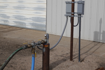
Now let’s move on to George’s arrangement. Rather than dig up his yard to make the settling and mud pits, he is using a portable mud pit. He has inserted a six inch diameter piece of PVC into the ground where he will be drilling. Then he attached a tee with a four inch pipe coming off the side. This four inch pipe leads to his portable mud pit
Below are a series of eMails George sent as he was drilling the well. As you can see, it took a bit of experimentation to find the right combination of size, speed, and drilling mud. He kept at it and his ultimate success is most impressive. I left off a couple of the first emails. As the story begins, George has a two inch pipe stuck in the ground from an effort using two water hoses as drilling fluid.
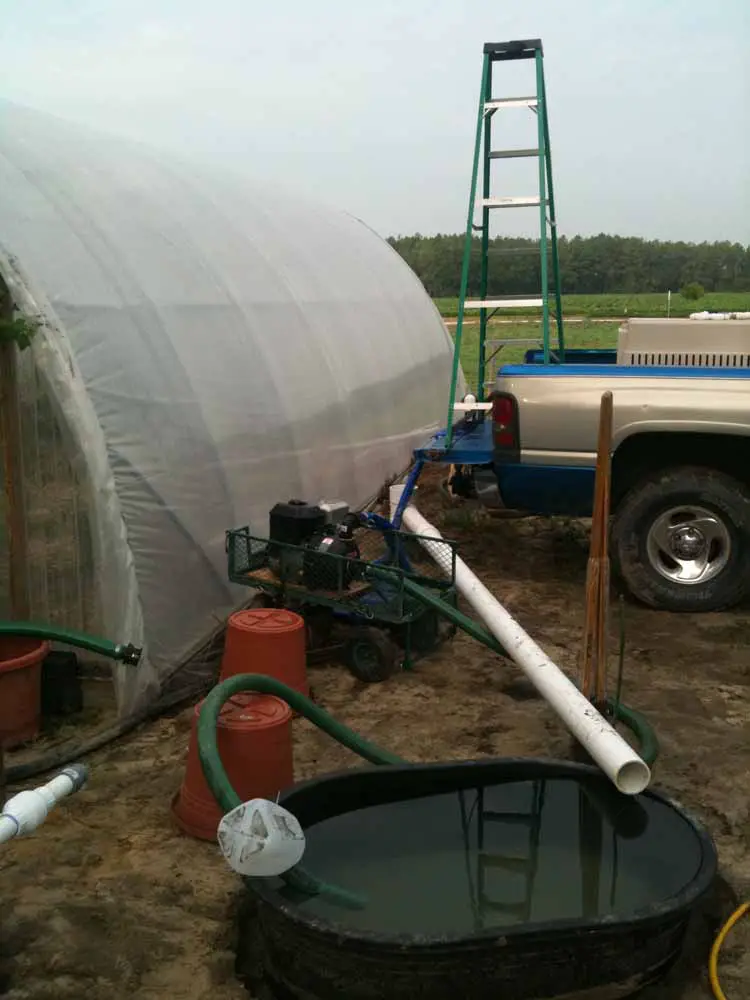
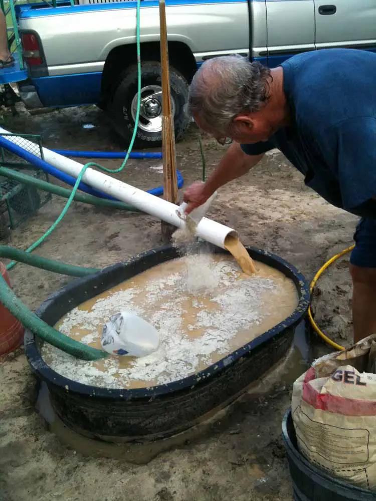
Using the mud pump method was GREAT ! I set everything up and had my neighbor over to help. I put the 20’ piece of 3″ pvc over my stuck 2″ pipe …. fired up the mud pump and got the water recirculating into my 110 gallon livestock tub. In less than 30 minutes, I had washed down to where the 3″ pipe was on top of the 2″ pipe. The 3″ pipe started wanting to stick in the soft sand, so I had my helper to add about 15 lbs. of “Aqua Gel” that I picked up at the plumbing store where I buy my well screens from. It’s a combination of bentonite and a vegetable polymer. Within a few minutes, I was able to easily slide the 3″ pipe up and down/side to side to enlarge my bore hole …… it quit caving in and sticking like it had been doingJ Instead of having to take the 2″ pipe out, both pipes washed down together ! At about 19’, I hit hardpan … so I decided to stop and pull out the 3″ pipe. After doing this, I had so much room left in the borehole, that I was able to pour 2 bags of pea gravel down the outside of my 2″ pipe all the way to the bottom …. without any caving in issues. I think I could have easily put down a 4″ pipe and well screen down that hole. The Aqua Gel was doing its job nicely.
Total time using the mud pump from starting to when I finished putting in the gravel pack was only 1 hour ! The guy at the plumbing shop told me I would have to backwash the well to remove the Aqua Gel because it would stop up the aquifer. I did that using my 110 gallon sprayer tank that was standing by full of clean water. I then hooked up my mud pump to the well and pumped it for 10 minutes … only getting about 9 gallons/minute flow. During this time, I filled my 110 gallon sprayer tank back up with clean water. I back flushed the well again …. after this time, I got a 16 gal/min flow …. getting better J On the third time I back flushed the well, I surged the mud pump from slow to fast … back and forth as it back flushed. Hooked everything back up and started pumping from the well ….. now getting 30 gal/min !! I decided to quit while I was ahead …. plus the temperature was pushing 100 degrees !!
Next weekend, I’m moving over about 14’ and putting down a second well so that I can eventually combine the two for my irrigation. I’ll take pictures and email them to you. I used a 6″ tee that had a 4″ side port to recirculate back to my 110 gallon stock tub. I only put 3’ of 6″ pvc in the ground and packed around the pipe to prevent leakage. Everything worked great … just like in the PVC video you sent me where the guy was using two dug pits to recirculate from.
next eMail)We jetted down the second well this past Saturday morning. It took only one hour from the time we started the pump until I finished with the gravel pack !! I used a 3″ pipe to jet with …. dropped in my 2″ pipe with 5’ well screen …. then pulled out the 3″ casing. At this point, there is enough room to pour 2.5 bags of pea gravel down the hole beside the well pipe. By using the Quick Gel, the hole does not cave in on the well pipe. The big difference this time was that I immediately back flushed the well with 110 gallons of fresh water to clear out the Quick Gel …. instead of trying to pump from it at the beginning like I did with my first well. This second well pumps a huge 60 gpm !!! I was amazed … to say the least. Tied together, both wells produce 90+ gpm with the pump slightly above idle speed J I’ve included some photos in this email and will send you some short videos in a follow up email. I hope it does not clog up your Inbox.Thanks so much for your help …… and inspiration from your website which got me started on this project !
Here are the short video clips. One thing I forgot to mention earlier was that you really have to mound up and pack the dirt around the bottom of your 6″ tee. We had a couple of times when the circulating water tried to come up around the 2.5 foot piece of 6″ pipe we had in the ground below the tee. It would be better if you could drive that pipe in the ground maybe another foot, but I did not have anything to do that with. Using the Quick Gel gives you enough time to stop and fix your leaks as you go without risking a cave in on your pipe.

Typically, well pumps can be broken down into two categories: jet pumps and submersible pumps. Each design is built to fit the needs of various well sizes and conditions.
Most shallow well pumps are found in wells that are less than 25 feet deep and in areas with a high water table. These pumps have few running parts and require little maintenance.
This type of pump is located above the ground, typically just inside the well house, and generates high pressure to pull the water from the well and into the home using an inlet pipe. A tank or well booster pump is recommended to accompany this type of well pump to increase water pressure to the home.
Unlike its shallow counterpart, a deep well jet pump is located within the well, though its motor stays in the well house. This pump uses two pipes: one for drawing water out of the well and another for directing the water to the home. Deep well jet pumps are typically used in wells that are 110 feet deep.
A deep well submersible pump sits at the bottom of the well directly in the water. Using its motor, the pump draws water from the bottom and pushes it out of the well into your home’s water lines. These pumps can be used in wells up to 300 feet deep. The pumps work similar to sump pumps, which draw water and pump it out.
Although professional well pump replacement comes with high pump installation costs, you may have no choice but to call a professional depending on the well pump you have. Certain pumps, like deep well submersible pumps, require special equipment to get them out without damaging components or wiring. In addition to the fragility of the well’s components, removing a well pump can be very labor intensive, with some pumps weighing more than 100 pounds.
Even if you’re considering replacing your well pump on your own, call a plumber to confirm that the well pump is the issue with your system before removing it. This will prevent any unneeded work or unintentional damage to your well system.
Use the tool below to find a well service contractor who can diagnose your well pump problem and help you determine whether or not you can replace it yourself:

This website is using a security service to protect itself from online attacks. The action you just performed triggered the security solution. There are several actions that could trigger this block including submitting a certain word or phrase, a SQL command or malformed data.
This website is using a security service to protect itself from online attacks. The action you just performed triggered the security solution. There are several actions that could trigger this block including submitting a certain word or phrase, a SQL command or malformed data.

Dug/Bored wellsare holes in the ground dug by shovel or backhoe. They are lined (cased) with stones, brick, tile, or other material to prevent collapse. Dug wells have a large diameter, are shallow (approximately 10 to 30 feet deep) and are not cased continuously.
Driven wells are constructed by driving pipe into the ground. Driven wells are cased continuously and shallow (approximately 30 to 50 feet deep). Though driven wells are cased, they can be contaminated easily because they draw water from aquifers near the surface. These wells draw water from aquifers near the surface.
Drilled wells are constructed by percussion or rotary-drilling machines. Drilled wells can be thousands of feet deep and require the installation of casing. Drilled wells have a lower risk of contamination due to their depth and use of continuous casing.
Well Casing is the tube-shaped structure placed in the well to maintain the well opening from the target ground water to the surface. Along with grout, the casing keeps dirt and excess water out of the well. This helps prevent contaminants from less desirable groundwater from entering the well and mixing with the drinking water. Some states and local governing agencies have laws that require minimum lengths for casing. The most common materials for well casing are carbon steel, plastic, and stainless steel. Local geology often dictates what type of casing can be used.
Well Caps are placed on top of the well casing to prevent debris, insects, or small animals from getting into the well. Well caps are usually made of aluminum or plastic. They include a vent to control pressure during well pumping.
Well Screens are attached to the bottom of the casing to prevent too much sediment from entering the well. The most common well screens are continuous slot, slotted pipe, and perforated pipe.
Jet Pumps are the most commonly used pumps for shallow wells (depth of 25 feet or less). Jet pumps are mounted above ground and use suction to draw water from the well.
Submersible Pumps are the most commonly used pumps for deep private wells. The pumping unit is placed inside the well casing and connected to a power source on the surface.
Proper well location and construction are key to the safety of your well water. The well should be located so rainwater flows away from it. Rainwater can pick up harmful bacteria and chemicals on the land’s surface. If this water pools near your well, it can seep into it and potentially cause health problems. The Center for Disease Control (CDC) has an excellent web page on well siting.
Appropriate well construction depends on local geologic and groundwater conditions. Your state water-well contractor licensing agency, your local health department, or a local water system professional can provide information on proper well construction. The National Ground Water Association (NGWA) provides a guide for hiring a water system professional that covers key considerations.
Make sure any water-well drillers and pump-well installers you work with are bonded and insured. If required in your state, make sure your ground water contractor is licensed and certified. Visit the National Ground Water Association to find certified water well contractors near you. The NGWA operates its own voluntary certification program for contractors . This allows drillers, and well pump installers can receive national training certification on top of state requirements. Some states actually use the Association’s exams as their test for licensing.

This website is using a security service to protect itself from online attacks. The action you just performed triggered the security solution. There are several actions that could trigger this block including submitting a certain word or phrase, a SQL command or malformed data.
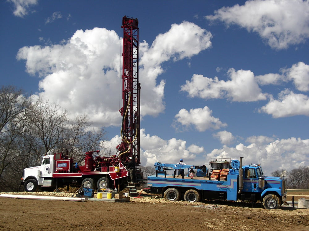
more at http://www.drillyourownwell.com This is an example of a Mud Pump Water Well Drilling Setup utilizing a Portable Mud pit. This particular well was ...
Mud pumps are the pumps deployed in the oil and gas industry, mainly to circulate drilling fluids and other kinds of fluids in and out of the drilled wells for exploration. The mud pumps transfer the fluids at a very high pressure inside the well using the piston arrangement. The number of pistons decides the displacement and efficiency of working of the mud pumps, originally only dual piston pumps and three-piston pumps were used, but the technological advancements have seen pumps with five and six pistons to come up. Currently the triplex pumps which have three pistons are used, but the duplex pumps having two pumps are still deployed in the developing countries.
Based on its types, global mud pump market can be segmented into duplex, triplex, and others. The triplex mud pumps will dominate the mud pump marking in the given forecast period owing to its advantages and ongoing replacement of duplex pumps with triplex pumps. Based on operation, the global mud pumps market can be segmented into electric and fuel engine.
The electric mud pumps will dominate the market during the given forecast period due to the advantage of eliminating the harmful carbon emission which is done in the case of fuel engine pumps. Based on its application, the global mud pumps market can be segmented into oil & gas, mining, construction, and others.
The major market driver for the global mud pumps market is the increasing exploration activities taking place in various regions of the world to satisfy the increased energy demand. The number of drilled wells has increased in recent years, which has certainly impacted the growth of the mud pumps market in both oil & gas and mining sectors.
Key market restraint for the global mud pumps market is the drift towards the cleaner sources of energy to reduce the carbon emissions, which will certainly decrease the demand for oil & gas and therefore will have a negative impact on the growth of the global mud pumps market.
Some of the notable companies in the global mud pump market are Mud King Products, Inc. Gardner Denver Pumps, Weatherford, Schlumberger, National Oilwell Varco, China National Petroleum Corporation, Flowserve Corporation, MHWirth, American Block, Herrenknecht Vertical Gmbh, Bentec GmbH Drilling & Oilfield Systems, Drillmec Inc, Sun Machinery Company, Shale Pumps, and Dhiraj Rigs.
The global mud pump market has been segmented into North America, Europe, Asia Pacific, Latin America, and Middle East & Africa. Owing to the well-established production sector and stable exploration industry North America holds the largest market for the mud pumps. The onshore exploration activities of oil & gas have increased at a good rate in the North America region, which has certainly boosted the growth of the mud pumps market in the region.
The demand from Europe and Asia Pacific has also increased due to exploration activities in both the regions owing to the increased energy demand. The energy demand specifically in the Asia Pacific has increased due to the increased population and urbanization. The Middle East and Africa also hold significant opportunities for the mud pumps market with increased exploration activities in the given forecast period.
In August 2018, Henderson which is a leading company in sales and service of drilling rigs, and capital drilling equipment in Texas signed a contract with Energy Drilling Company for the purchase and upgrade of oil field equipment’s which included three 1600hp × 7500psi mud pumps. This will be the first refurbishment completed at Henderson’s new service center and rig yard.
In January 2018, Koltek Energy Services launched the 99-acre facility for the testing of the oil field equipment in Oklahoma. This will allow the oil field equipment manufacturers to test their equipment at any given time. The company has deployed the MZ-9 pump which has a power rating of 1000Hp.

You may know that groundwater serves many purposes worldwide. Of course, drinking water and domestic uses of water are major components of those uses. The ways of getting at groundwater differ depending on the local underground conditions. Water may be plentiful just 10 feet below the land surface, or a deep well might have to be drilled many hundreds of feet to get at scarcer water filling the cracks between dense rock particles. Pumps are often needed to push water to the land surface.But this little lad is lucky as his well is located in a place where groundwater is shallow and plentiful. Thus, he, with his parents" help, can just hand-lower the bucket a few feet down and crank the bucket full of water back to the surface. This picture does not show a working well, but wells just like this have served the water needs of people for many centuries and still do today.
There"s a good chance that the average Joe who had to dig a well in ancient Egypt probably did the work with his hands, a shovel, and a bucket. He would have kept digging until he reached the
Digging a well by hand is becoming outdated today as automated drilling methods replace manual-labor methods. Modern wells are more often drilled by a truck-mounted drill rig. Still, there are many ways to put in a well — here are some of the common methods.
Hacking at the ground with a pick and shovel is one way to dig a well. If the ground is soft and the water table is shallow,then dug wells can work. Historically, dug wells were excavated by hand shovel to below the water table until incoming water exceeded the digger"s bailing rate. The well was lined with stones, brick, tile, or other material to prevent collapse, and was covered with a cap of wood, stone, or concrete. They cannot be dug much deeper than the water table — just as you cannot dig a hole very deep when you are at the beach... it keeps filling up with water!
Dug and bored wells have a large diameter and expose a large area to the aquifer. These wells are able to obtain water from less-permeable materials such as very fine sand, silt, or clay. Some disadvantages of this type of well are that they are shallow and lack continuous casing, making them subject to contamination from nearby surface sources, and they go dry during periods of drought if the water table drops below the well bottom.
Driven wells are still common today. They are built by driving a small-diameter pipe into soft earth, such as sand or gravel. A screen is usually attached to the bottom of the pipe to filter out sand and other particles. Problems? They can only tap shallow water, and because the source of the water is so close to the surface,
Most modern wells are drilled, which requires a fairly complicated and expensive drill rig. Drill rigs are often mounted on big trucks. They use rotary drill bits that chew away at the rock, percussion bits that smash the rock, or, if the ground is soft, large auger bits. Drilled wells can be drilled more than 1,000 feet deep. Often a pump is placed in the well at some depth to push the water up to the surface..Wells and Pumpage
Pumping a well lowers the water level around the well to form a cone of depression in the water table. If the cone of depression extends to other nearby wells, the water level in those wells will be lowered. The cone develops in both shallow water-table and deeper confined-aquifer systems. In the deeper confined-aquifer system, the cone of depression is indicated by a decline in the pressure and the cone spreads over a much larger area than in a water-table system. For a given rate of withdrawal, the cone of depression extends deeper in low-yielding aquifers than in high-yielding ones.
Well Casing is the tube-shaped structure placed in the well to maintain the well opening from the target ground water to the surface. Along with grout, the casing keeps dirt and excess water out of the well. This helps prevent contaminants from less desirable groundwater from entering the well and mixing with the drinking water. Some states and local governing agencies have laws that require minimum lengths for casing. The most common materials for well casing are carbon steel, plastic, and stainless steel. Local geology often dictates what type of casing can be used.
Well Caps are placed on top of the well casing to prevent debris, insects, or small animals from getting into the well. Well caps are usually made of aluminum or plastic. They include a vent to control pressure during well pumping.
Well Screens are attached to the bottom of the casing to prevent too much sediment from entering the well. The most common well screens are continuous slot, slotted pipe, and perforated pipe.
Jet Pumps are the most commonly used pumps for shallow wells (depth of 25 feet or less). Jet pumps are mounted above ground and use suction to draw water from the well.
Submersible Pumps are the most commonly used pumps for deep private wells. The pumping unit is placed inside the well casing and connected to a power source on the surface.
The groundwater well has been with us since ancient times and has allowed our species to populate land areas where surface water is not available. Though the design and construction of wells has changed and technology has produced pumps with amazing capabilities, the aquifer that supplies the well remains the same.
Many people get their drinking water from fresh water aquifers but few understand how or why you get pure water by simply drilling a hole in the ground and fewer still have any idea how the operation of their water system can affect the quality and sustainability of the water supply. In fact, aquifer/well relationships can be much more complicated than they appear and much of the damage we do to them results from actions that “seemed like a good idea at the time.”
The water well is your personal connection to nature’s infrastructure, the local aquifer. This connection means that millions of gallons of water are available for your use but the rate at which it flows into your well is determined by the makeup of the ground in which the well is constructed and the way that you operate it. That’s right, the way you operate the well can determine the quality and quantity of the water you get and the length of service the well will provide.
Most people know someone who has had to drill a new well because the old one “went dry.” The cause was a complete mystery and the fact that the driller was able to drill another good well only 50’ away raised no questions. The person with the dry well was just glad to have water again.
Had they stopped to think about it they might have wondered why a new hole so close found water when the one just over there was now dry. Obviously the aquifer still has water in it and the new well probably filled up just as high as the old one did when it was new, so what happened?
If theirs was a low yield well, chances are it was the way the well was operated that caused it to “run dry.” Conventional pumping systems remove water from the well until the end use is satisfied, whether that end use is your shower or a storage tank that needs filling. In a slow or low yield well, the water column is constantly being drawn down when demand for water exceeds the rate at which it flows into the well. Pumping water out of a well faster than it comes in is called over pumping. Periods of extended over pumping increase the rate at which water travels through the ground immediately around the well drawing in sediment that adds cloudiness to the water and may eventually clog the cracks that are the arteries in your water delivery system thus severing the well’s connection to the aquifer.
Every well that is being pumped has some influence on the surrounding area. When a well is pumped, the nearby water starts flowing in immediately, draining the ground around the well while the more distant water flows in to replace that which entered the well. This difference in rate of travel results in a cone shaped depression in the aquifer around the well that gets shallower as you get further from the well, growing in size the longer you keep the well level drawn down.
Once pumping ceases the cone of depression slowly fills in as water from a distance moves toward the area of lower pressure. Because this cone influences the movement of water through the aquifer it is said to create a “zone of influence” which affects the way water flows through the geology in the vicinity of the well.
When a well withdraws water slowly from an aquifer the only contaminants that are likely to affect it are those directly upstream from the well but over pumping increases the radius of influence that a well creates – its zone of influence – and can even reverse the direction of natural flow in the aquifer. The influence created by pumping hard draws water from 360 degrees around the well, bringing contaminants such as brine from nearby bodies of salt water, nitrates and fertilizers from adjacent farm land, surface water from streams or even leakage from underground storage tanks to the last place you want it; your water supply.
When a well is pumped more slowly we benefit from the aquifer’s natural tendency to dilute contaminants and when we pump too hard we cause the contaminants to be concentrated and drawn to the well.
The negative effects of over pumping are cumulative and lasting. When you over pump an aquifer the result can be the spreading of contamination or even land subsidence. Subsidence is the settling of ground and may be caused by a number of natural occurrences but more than 80 percent of the subsidence in the United States is related to the withdrawal of ground water1. When land subsides, it is compacting. The spaces in the ground are closing and therefore the ground lowers or subsides. If you look at the definition of an aquifer2 you see that it is the spaces that contain the water. Once those spaces disappear the aquifer’s ability to store water is reduced forever. A long rainy season or good snow melt is not going to recreate voids that have closed.
When a well is over pumped, water is withdrawn faster than it is coming in and the water level in the well drops dramatically as the geology around the well drains. The longer this goes on the more widespread the dewatered area is. When the nearby cracks and voids are emptied of water they may collapse if they were not self supporting.
This phenomenon is most obvious in hydrofractured wells that suffer from diminishing yield. If you review a description of hydrofracturing3 you will see why. Though many hydrofractured wells show an increase in production, it is often not enough to take them from low yield to great producers. When a low yield well is pumped by conventional means there will be times when it is pumped quite low. If the level in the well is reduced enough that the fractures opened by hydrofracting are out of the water and draining they can suffer from subsidence. The water was the wedge that created or widened the fracture and has been helping hold it open. Once the wedge is removed the fracture can slowly close back up decreasing yield and increasing the frequency of out of water events. The end result is that, over time, you can end up right back where you started. This is a phenomenon which those who hydrofracture oil and gas wells understand and is the reason that some inject sand with the water used in that process.
Even in the short term over pumping can result in decreased well yield. Dewatering is what causes the cone of depression around a well. The longer this goes on the larger the cone (dewatered area) becomes. The deeper and wider the cone, the smaller the interface between the well and aquifer and the lower the well yield will be. This should not come as shocking news as it is the purpose of a dewatering operation; to lower the groundwater level and decrease the inflow rate so that an area can be excavated. Whether on purpose or by accident, the result of over pumping is dewatering and this is not an efficient way to operate a well intended as a continuing source of water.
Recently a gentleman approached us asking if we could get more water from his wells. He had two 900’ wells that fed a 4200 gallon buried storage tank which he used to supply an irrigation system. The well pumps ran continually trying to keep up with the irrigation system’s needs but were failing to do so. When we suggested that he would get more water by pumping less he thought we were insane. It took a great deal of convincing but in the end he bought a Well Manager duplex well control system, a PumpChamber for the 4200 gallon tank and a Consistent Pressure Module for the irrigation system. The end result was that the 4200 gallon tank now fills in 1/3rd the time and the wells are easily keeping up with the irrigation. Now, you are wondering, how this could be?
The explanation can be found in a combination of factors. First, the well pumps are delivering more gpm now because the wells are running nearly full and they do not have to lift the water from 800 feet. Second, the well yield is increased because he is no longer dewatering the area and reducing the well’s interface with the aquifer. Of course, since the pumps run a lot less, his electric bill is reduced dramatically.
This demonstrates that you get the most from a well when withdrawals are in step with the rate at which the aquifer can transmit water. When pumping is in excess of the transmission rate the operation changes from water harvesting to dewatering and well yield begins to decline.
Over pumping threatens the well’s longevity not only through subsidence and dewatering but also through mineral or biological buildup. Wells fed by fractures, those that dribble in through tight shale or those with well screens are all susceptible to loss of production resulting from buildup of mineral crust or bio-slimes. This buildup can be hastened by continually over pumping and exposing the well walls to the air. The same minerals that cause buildup on your faucet aerator or create stalactites and stalagmites in caves can build up where water comes into the well bore reducing the well yield and eventually seal it off from the aquifer.
Arsenic in groundwater has been a hot topic for some time. The current federal limit in drinking water is 10 ppb (parts per billion) but some local jurisdictions have already adopted a lower 5ppb limit as the EPA has stated their intention to lower the maximum contaminant level again. New Jersey and other states now require a water test when you sell your home. If there is too much arsenic in the water, treatment is required and can be expensive.
Arsenic exists in nature in combination with other elements like iron or sulfur in the form of various minerals. It is the oxidative breakdown of these minerals that releases the arsenic into water. Natural changes in the water table can result in mineral oxidation but over pumping can make the situation worse. Over pumping a well exposes the geology in the cone of depression to the air. If there are arsenic-bearing minerals in that geology, arsenic can be released by oxidation and picked up in the water when the cone of depression fills back in after pumping ceases. Many experts now suspect that unacceptable levels of arsenic in well water are another unintended consequence of over pumping.
It is this reality that has led Dave Johnson and Tom Riewe of the Bureau of Drinking Water and Groundwater, Department of Natural Resources, Madison, Wisconsin, to recommend the testing of well water for arsenic every couple of years4. Other agencies around the world are recognizing that over pumping is the most common cause of premature well failure5. Some have rewritten their groundwater law to reflect this6.
Unfortunately, the most commonly installed system to deal with low-yield wells is a cistern-type system. Most of these cistern and similar above-ground tank systems control the well pump with a tank full float. When the tank is not full the well pump is turned on to replace the water used from the tank. The float keeps the well pump running until the tank is refilled but on occasion, when use is heavy and ongoing, there may not be enough water stored in the well to refill the tank and keep up with ongoing use.
To prevent the well pump from running when the well is empty most contractors install a motor protector with a timed reset so that the pump is turned off for a time while the well refills. Some people call these “well timers” but they were designed to protect well pumps from burnout due to dry running and are not a good operating mechanism to collect water from a low yield well because they only turn the well pump off AFTER the well is emptied. Constantly over pumping the well like this reduces well yield, increases the likelihood the well will be frequently pumped down, results in attracting dirt and contaminants and contributes to its early demise through mineral encrustation, bio-fouling, subsidence, and all the other factors discussed above. Why? Because the well must be pumped empty for the motor protector to shut the pump off. The well ends up being operated like a sump pump pit as it is emptied time and again until the cistern is full.
Well Manager was designed to work as it does because we realized early on that over pumping was a major cause of well failure and that you could actually get more from a well by pumping more slowly. Well Manager is the only “off the shelf” well water harvesting system that works to balance your water needs with the natural hydrologic cycle by getting in step with the rate at which nature delivers water to your well. The Well Manager® system is designed to be flexible so it can deal with a well yield that varies from season to season without over pumping while delivering constant, dependable service to your home, church, or school.
If the rate of flow into your well is 1 gallon per minute (GPM), then over the course of a 24-hour or 1440 minute time span it is capable of delivering 1440 gallons of water or enough to supply three to four times the amount of water to satisfy a household of four. In order to collect this much water from a well, however, you must keep it producing. Most wells produce only a fraction of their potential because standard pressure tank systems only withdraw water from the well when someone is using water and so allows them to be at rest most of the time.
The Well Manager® system, patented in the US and Canada, collects smaller amounts of water at regular timed intervals whether you are using water or not and is adjustable so it is possible to collect the entire production of a well or to limit the amount of water that can be withdrawn. Managing a well in this way means that it can be kept producing as long as necessary while maintaining it in a nearly full condition. This reduces the well’s adverse influence on the aquifer, the likelihood that debris and contaminants will be drawn to it, reduces the risk of releasing arsenic from minerals by oxidation, eliminates the damage to the feeding fractures caused by continually over pumping and minimizes the likelihood that air drawn into the well will cause contamination there.
The system’s atmospheric storage tank has a filtered air breather and is designed to handle peak demand; water is pumped from the well column at precisely timed intervals, generally 1, 2 or 3 times per hour. During each harvesting, the pump is run for only a few minutes and the interval between pump activations is more than adequate to keep the motor from overheating. By setting the Well Manager to retrieve water in this manner, the water level recovers between each pump interval and remains fairly high in the well bore, minimizing the cone of depression and all of the problems associated with it.
Maintaining the well in this condition throughout the operating cycle reduces the amount of air drawn in dramatically and the rate at which water travels through the ground. Slower, more natural water movement lowers the amount of oxygen in the water and reduces or eliminates the debris that faster-moving water often brings with it. As a result, many Well Manager customers find that their water clarity improves dramatically and that the contaminants revealed in their water tests is reduced over time.
A Well Manager® pumping at nature’s pace brings you more, better quality water and provides you with the satisfaction of knowing you have the most environmentally sensitive water harvesting system available anywhere!
An aquifer covers many square miles and is composed of spaces filled with water in the various layers of material beneath the ground. In one area there may be sand or gravel deposits, in another the shale may contain many fractures, and in still others dense rock formations may have relatively few spaces (voids) in the form of fractures created by the cooling and heating of the earth’s crust. These cracks and voids fill with water that soaks down through the ground and together form a water-bearing stratum called an aquifer.
Hydrofracturing – Water is pumped into the well bore quickly building pressure until a sudden drop in pressure occurs indicating a breakthrough. If the pressure was high enough, the rock pressure is overcome, the rock is cracked and a fluid-filled fracture is opened up. The overburden can actually be lifted up and pumping in more fluid can extend the crack. [The overburden is the rock layers above the fractured rock.] It is not necessary to have very large cracks to increase the permeability dramatically (tenths of an inch or less)


 8613371530291