
mud pump gear ratio calculator in stock

Rig pump output, normally in volume per stroke, of mud pumps on the rig is one of important figures that we really need to know because we will use pump out put figures to calculate many parameters such as bottom up strokes, wash out depth, tracking drilling fluid, etc. In this post, you will learn how to calculate pump out put for triplex pump and duplex pump in bothOilfield and Metric Unit.

Pump Output per Stroke (PO): The calculator returns the pump output per stroke in barrels (bbl). However this can be automatically converted to other volume units (e.g. gallons or liters) via the pull-down menu.
A triplex mud (or slush) pump has three horizontal plungers (cylinders) driven off of one crankshaft. Triplex mud pumps are often used for oil drilling.
We provide hydraulic components & repair services for industrial applications like paper mills, saw mills, steel mills, recycling plants, oil & gas applications and mobile applications, including construction, utility, mining, agricultural and marine equipment. This includes hydraulic pumps, motors, valves, servo/prop valves, PTOs, cylinders & parts.

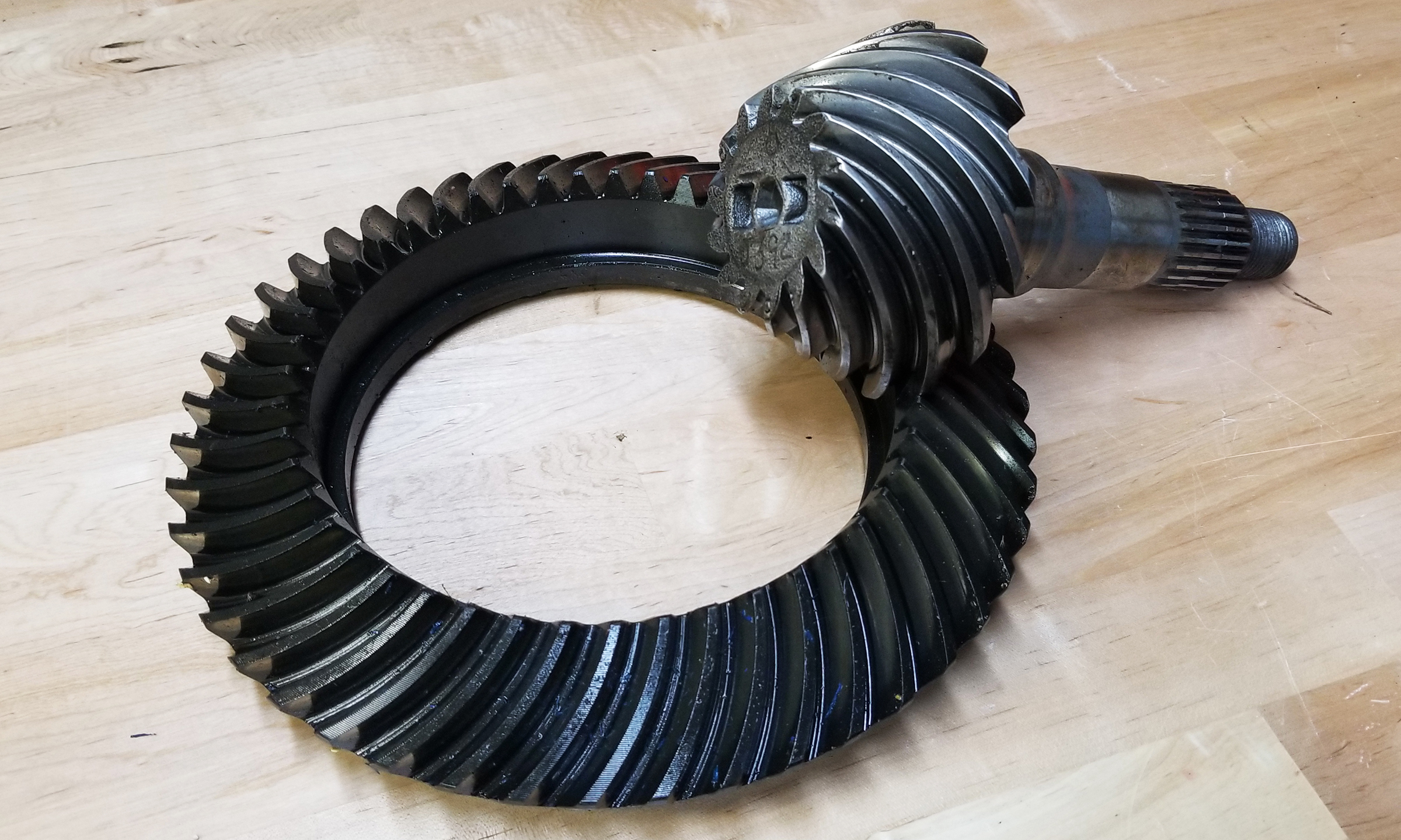
Okay, so you"ve torn your pumpkin apart and have the ring gear and pinion gear teeth count. This calculator will give you the gear ratio, just plug in the numbers.

Pumps tend to be one of the biggest energy consumers in industrial operations. Pump motors, specifically, require a lot of energy. For instance, a 2500 HP triplex pump used for frac jobs can consume almost 2000 kW of power, meaning a full day of fracking can cost several thousand dollars in energy costs alone!
So, naturally, operators should want to maximize energy efficiency to get the most for their money. Even a 1% improvement in efficiency can decrease annual pumping costs by tens of thousands of dollars. The payoff is worth the effort. And if you want to remotely control your pumps, you want to keep efficiency in mind.
In this post, we’ll point you in the right direction and discuss all things related to pump efficiency. We’ll conclude with several tips for how you can maintain pumping efficiency and keep your energy costs down as much as possible.
In simple terms, pump efficiency refers to the ratio of power out to power in. It’s the mechanical power input at the pump shaft, measured in horsepower (HP), compared to the hydraulic power of the liquid output, also measured in HP. For instance, if a pump requires 1000 HP to operate and produces 800 HP of hydraulic power, it would have an efficiency of 80%.
Remember: pumps have to be driven by something, i.e., an electric or diesel motor. True pump system efficiency needs to factor in the efficiency of both the motor AND the pump.
Consequently, we need to think about how electrical power (when using electric motors) or heat power (when using combustion engines) converts into liquid power to really understand pump efficiency.
Good pump efficiency depends, of course, on pump type and size. High-quality pumps that are well-maintained can achieve efficiencies of 90% or higher, while smaller pumps tend to be less efficient. In general, if you take good care of your pumps, you should be able to achieve 70-90% pump efficiency.
Now that we have a better understanding of the pump efficiency metric, let’s talk about how to calculate it. The mechanical power of the pump, or the input power, is a property of the pump itself and will be documented during the pump setup. The output power, or hydraulic power, is calculated as the liquid flow rate multiplied by the "total head" of the system.
Remember: we’re trying to find the ratio of power in to power out. Since rations require equal units on both sides, we"ll have to do some conversions to get our hydraulic power units in HP. You"ll see how this is done in the example below.
IMPORTANT: to calculate true head, you also need to factor in the work the pump does to move fluid from the source. For example, if the source water is below the pump, you need to account for the extra work the pump puts in to draw source water upwards.
*Note - this calculation assumes the pump inlet is not pressurized and that friction losses are minimal. If the pump experiences a non-zero suction pressure, or if there is significant friction caused by the distance or material of the pipe, these should be factored in as well.
You"ll notice that the elevation head is minimal compared to the discharge pressure, and has minimal effect on the efficiency of the pump. As the elevation change increases or the discharge pressure decreases, however, elevation change will have a greater impact on total head.
Obviously, that’s a fair amount of math to get at the pump efficiency, considering all of the units conversions that need to be done. To avoid doing these calculations manually, feel free to use our simple pump efficiency calculator.
Our calculations use static variables (pump-rated horsepower and water source elevation) and dynamic variables (discharge flow and pressure). To determine pump efficiency, we need to measure the static variables only once, unless they change.
If you want to measure the true efficiency of your pump, taking energy consumption into account, you could add an electrical meter. Your meter should consist of a current transducer and voltage monitor (if using DC) for electrical motors or a fuel gauge for combustion. This would give you a true understanding of how pump efficiency affects energy consumption, and ultimately your bank account.
Up until this point, we’ve covered the ins and outs of how to determine pump efficiency. We’re now ready for the exciting stuff - how to improve pump efficiency!
One of the easiest ways to improve pump efficiency is to actually monitor pumps for signs of efficiency loss! If you monitor flow rate and discharge (output power) along with motor current or fuel consumption, you’ll notice efficiency losses as soon as they occur. Simply having pump efficiency information on hand empowers you to take action.
Another way to increase efficiency is to keep pumps well-maintained. Efficiency losses mostly come from mechanical defects in pumps, e.g., friction, leakages, and component failures. You can mitigate these issues through regular maintenance that keeps parts in working order and reveals impending failures. Of course, if you are continuously monitoring your pumps for efficiency drops, you’ll know exactly when maintenance is due.
You can also improve pump efficiency by keeping pumps lubricated at all times. Lubrication is the enemy of friction, which is the enemy of efficiency (“the enemy of my enemy is my friend…”).
A fourth way to enhance pump efficiency is to ensure your pumps and piping are sized properly for your infrastructure. Although we’re bringing this up last, it’s really the first step in any pumping operation. If your pumps and piping don’t match, no amount of lubricant or maintenance will help.
In this post, we’ve given you the full rundown when it comes to calculating and improving pump efficiency. You can now calculate, measure, and improve pump efficiency, potentially saving your business thousands of dollars annually on energy costs.
For those just getting started with pump optimization, we offer purpose-built, prepackaged solutions that will have you monitoring pump efficiency in minutes, even in hazardous environments.

In this article discussed about pump basic formulas with examples likepump power calculation formula, specific speed of centrifugal pump and affinity laws for centrifugal and displacement pumps. Also provided online calculator for pump power calculation
The work performed by the pump is equal to the weight of liquid pumped in Unit time multiplied by total Head in meters. However the pump capacity in M3/hr and liquid specific gravity are used rather than weight of liquid pumped for work done by the pump.
The input power “P” of a pump is the mechanical power inkW or Watt taken by the shaft or coupling. So the input power of the pump also called Break Horse Power (BHP).
Pump output power is called as Water Horse Power (WHP ) or Hydraulic power and it is useful work delivered by the pump. and is usually expressed by the formula
The specific speed “Nq” is a parameter derived from a dimensional analysis which allows a comparison of impellers of various pump sizes even when their operating similar Q -H range. The specific speed can be used to classify the optimum impeller design.
Specific Speed of pump (Nq) is defined as the speed in RPM at which a geometrically similar impeller would run if it were reduced proportionately in size so as to delivered 75 kg of water per second to the height of 1 m.
Pump Efficiency is the most important factor while calculating power consumption. So while selection of the higher rating of pump always choose best efficiency pump set.

Determining the flow rate you will need is an essential part of planning your system design, before you go ahead and order or install your new pump. If you get this wrong, then you might have to invest money in replacement equipment which could seriously impact your budget.
All of these considerations will be specific to your project. The volume of fluid you wish to transport over a given time will be your flow rate, while the type of material and the distance between input and output will affect the flow rate you can realistically achieve. Therefore, these three aspects of a healthy system are all interlinked.
Once your system is installed and you have chosen the correct pump for the job, you will need to assess the system"s performance. There are a number of factors you could measure, but right now we will stick with flow rate. To measure the flow rate of your system you can:
Use a Flow Meter: This is a simple device which can measure the amount of fluid passing through it. Attach this to your discharge pipe, as close as possible to your pump and it should give you a reliable reading of your flow rate.
If the flow rate is not what it should be, given the expected performance of your installed pump, then you can move on and begin to assess each piece of your system for flaws. You may be interested in this blog:
Or, It could be that your pump is simply in need of replacement. If so, Global Pumps has a range of excellent industrial pumps available for any circumstance.

We commonly receive the call to help assist in properly sizing pulleys and sheaves for pump applications. Generally, this is in high pressure wash applications but we also run into a fair amount of agricultural applications where this knowledge can be leveraged. Pulleys or “sheaves” are commonly used for connecting pumps to motors or engines via drive belts. Most pulleys are cast iron or aluminum construction and are offered in either fixed-bore or tapered bushing styles.
For proper operation of any brand or pump type, it is critical to size pulleys and sheaves, correctly, in order to maintain correct RPM, (revolutions per minute). RPM speed is what determines the pump output flow rate – in gallons per minute, liters per minute, etc.
Incorrect pump RPM will adversely affect the pump performance. If the pump is turning too slow – it will not give full performance. Conversely, if the pump is turning too fast, it could cause premature mechanical failures (i.e. valve wear or elastomer failure).
Therefore, it is absolutely critical to ensure correct pulley sizing and analysis of the drive unit, (motor, engine, etc.) relative to the pump. For the sake of this discussion, we will assume standard electric motors at 1750 RPM and standard gas engines at 3400RPM. Do note, one must determine the rpm of their drive unit to be able to accurately calculate the pulley/sheave size.
If you start with an incorrect figure for RPM – you will size your equipment incorrectly. This could lead to shorter equipment lifespans and/or reduced output flow rates. Thus, ultimately a less efficient system which equates to more down time and added cost of operation. The scope of this post will be focused towards plunger pump applications. We assemble many units using this method in Omaha, NE. Dultmeier Sales is proud to display the Built in the USA logo on our products. Here are just a handful of the pulley-driven pump products that we offer.
There are complicated formulas for determining pulley ratios but in generic, layman terms, simply divide the driven component (pump) by RPM, the driver component (motor or engine) rated by RPM to get the required ratio. In the example below, the pump RPM is 1070, for full output, while the motor is 1750 RPM.
This means the pulley ratio must be .611 to drive the pump correctly. Hypothetically speaking, if we had a 4 inch pulley on the motor, we would require a 6.55” pulley on the pump. That mathematical equation is as follows: 4” divided by .611 = 6.55”
If the drive pulley on the engine is 4 inches in diameter, we need to calculate 4/.315 = 12.70. This means that the pump pulley must be 12.70 inches, in diameter, to run the pump at 1070 rpm. You can view a technical page from our catalog here – it will help to further explain the calculation process.
Most pulleys, or sheaves, are designed with either fixed shaft bores or tapered bushing hubs. Replaceable hubs fit the required motor or pump shaft size in either inch or mm sizes – depending on the application requirement. These hubs come with bolts to attach them to the pulley, or sheave.
Tapered style hubs simply fit into the pulley opening and then are tightened with two or three set screws, which draw the bushing and pulley together to make one assembly. The pulleys are then attached to the driver (electric motor or gas engine) and driven components (pump). The type of hub, H, SD, SH, etc. must match to a pulley with the same designation for proper fit.
A belts are not as wide as B belts and, therefore, sit lower in the pulley groove. While this may seem as a minor detail – it absolutely affects the ratio measurement when properly sizing a pulley.
As the information above shows, there are many things involved in order to determine the correct pulleys required to drive your pumps correctly. It is important to remember the larger the difference in pulley sizes, the larger the center distance required to maintain minimum contact with the smaller pulley. We would be glad to help with any sizing for your specific applications. Your Experts in Delivering Fluid Handling Solutions – We Know Flow!

The motor used to power a centrifugal pump needs to be able to produce enough torque to start the pump and bring it to an optimal operating speed. If a motor lacks enough torque to operate a pump, the pump may not start or may only operate at a reduced speed. The centrifugal pump suppliers at PumpWorks will guide you through the pump motor selection process.
A pump’s torque-speed curve is used to determine the appropriate motor to match with it. A pump’s torque-speed curve is produced by plotting the percentage of full load torque (FLT) vertically against the percentage of full load speed (FLS) plotted horizontally. An example is shown below.
The torque-speed curve is similar for all centrifugal pumps due to simple math: the pump torque varies as the square of its speed. However, when the pump is at rest—0% full load speed—the full load torque is never also 0%. Starting a rotating pump requires the motor to overcome the pump inertia and static friction.
To overcome pump inertia and static friction, approximately 20% of full load torque is required. As the pump’s speed increases, the required torque gradually declines. For example, at about 15% full load speed the required torque typically is around 5% or 10% full load torque. As shown below, the pump torque-speed curve follows the square law:
Like pumps, motors produce a torque-speed curve of their own. By overlaying the torque-speed curve of a pump and a motor, one can verify that the motor is producing enough accelerating torque to drive the pump to full speed, as shown below.
In this overlay the shaded area reflects the accelerating torque available from the motor to drive the pump. Where the two curves intersect is the point at which the motor’s torque is insufficient to drive the pump any faster. In other words, this is the point of maximum pump speed while powered by this motor.
Torque at zero flow is especially important for pumps with axial flow (or propeller) designs. The torque-speed curve of such pumps is such that the highest HP, and therefore the highest torque, is required at zero flow. An axial-flow pump must be paired with a motor with adequate HP to get the pump moving.
Another important factor in motor selection is the pump’s inertia value at the motor shaft. Inertia is a measure of an object’s resistance to movement change. The higher the pump inertia, the longer the motor will take to start the pump and bring it to full load speed.
This is significant because motors draw current to bring pumps up to speed. The longer a motor takes to overcome a pump’s inertia, the more heat it will generate. A motor must be sized to handle the pump’s inertia to avoid damaging the motor’s windings.
If a motor directly drives the pump, the values of the pump and pump-motor coupling inertias are the same regardless of pump speed. If the pump is driven by a gearbox and motor, however, the gearbox can have a major impact on inertia values. In this application inertia can be expressed as:
A gearbox’s effect on inertia can be understood by analogy to a bicycle. When a bicycle is ridden at high speeds, the rider may change to a higher gear ratio (one greater than 1.0) to go faster. Such a ratio also requires the rider to put in more effort. Likewise, if a gearbox shifts to a higher gear ratio, the motor will have a higher load. The same logic applies if the gearbox is reducing the motor speed to drive the pump slower. When the gearbox ratio is less than 1.0, it will reduce the load requirements on the motor.
Selecting the right pump and motor for a specific application can be a complex job. The team at PumpWorks is dedicated to finding pump solutions that meet the exact needs of each customer.

When two (or more) pumps are arranged in serial their resulting pump performance curve is obtained by adding theirheads at the same flow rate as indicated in the figure below.
Centrifugal pumps in series are used to overcome larger system head loss than one pump can handle alone. for two identical pumps in series the head will be twice the head of a single pump at the same flow rate - as indicated with point 2.
With a constant flowrate the combined head moves from 1 to 2 - BUTin practice the combined head and flow rate moves along the system curve to point 3. point 3 is where the system operates with both pumps running
When two or more pumps are arranged in parallel their resulting performance curve is obtained by adding the pumps flow rates at the same head as indicated in the figure below.
Centrifugal pumps in parallel are used to overcome larger volume flows than one pump can handle alone. for two identical pumps in parallel and the head kept constant - the flow rate doubles compared to a single pump as indicated with point 2
Note! In practice the combined head and volume flow moves along the system curve as indicated from 1 to 3. point 3 is where the system operates with both pumps running
In practice, if one of the pumps in parallel or series stops, the operation point moves along the system resistance curve from point 3 to point 1 - the head and flow rate are decreased.


 8613371530291