
mud pump lubrication system free sample

Created specifically for drilling equipment inspectors and others in the oil and gas industry, the Oil Rig Mud Pump Inspection app allows you to easily document the status and safety of your oil rigs using just a mobile device. Quickly resolve any damage or needed maintenance with photos and GPS locations and sync to the cloud for easy access. The app is completely customizable to fit your inspection needs and works even without an internet signal.Try Template

I’ve run into several instances of insufficient suction stabilization on rigs where a “standpipe” is installed off the suction manifold. The thought behind this design was to create a gas-over-fluid column for the reciprocating pump and eliminate cavitation.
When the standpipe is installed on the suction manifold’s deadhead side, there’s little opportunity to get fluid into all the cylinders to prevent cavitation. Also, the reciprocating pump and charge pump are not isolated.
The gas over fluid internal systems has limitations too. The standpipe loses compression due to gas being consumed by the drilling fluid. In the absence of gas, the standpipe becomes virtually defunct because gravity (14.7 psi) is the only force driving the cylinders’ fluid. Also, gas is rarely replenished or charged in the standpipe.
The suction stabilizer’s compressible feature is designed to absorb the negative energies and promote smooth fluid flow. As a result, pump isolation is achieved between the charge pump and the reciprocating pump.
The isolation eliminates pump chatter, and because the reciprocating pump’s negative energies never reach the charge pump, the pump’s expendable life is extended.
Investing in suction stabilizers will ensure your pumps operate consistently and efficiently. They can also prevent most challenges related to pressure surges or pulsations in the most difficult piping environments.

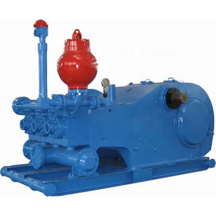
The 2,200-hp mud pump for offshore applications is a single-acting reciprocating triplex mud pump designed for high fluid flow rates, even at low operating speeds, and with a long stroke design. These features reduce the number of load reversals in critical components and increase the life of fluid end parts.
The pump’s critical components are strategically placed to make maintenance and inspection far easier and safer. The two-piece, quick-release piston rod lets you remove the piston without disturbing the liner, minimizing downtime when you’re replacing fluid parts.

Mystique Mud pump Coolant and Lubricant extends mud pump liner and piston life and provides internal lubrication and extra cooling to the coolant system of mud pumps. It extends the life of all liners, even ceramic. Mystique will not cause corrosion or rusting of iron, and is safe with all alloys. Recommened dilution rate of 12.5%. (25 gallons will treat a 200-gallon system.) For use on closed systems.
If you run a mud rig, you have probably figured out that the mud pump is the heart of the rig. Without it, drilling stops. Keeping your pump in good shape is key to productivity. There are some tricks I have learned over the years to keeping a pump running well.
First, you need a baseline to know how well your pump is doing. When it’s freshly rebuilt, it will be at the top efficiency. An easy way to establish this efficiency is to pump through an orifice at a known rate with a known fluid. When I rig up, I hook my water truck to my pump and pump through my mixing hopper at idle. My hopper has a ½-inch nozzle in it, so at idle I see about 80 psi on the pump when it’s fresh. Since I’m pumping clear water at a known rate, I do this on every job.
As time goes on and I drill more hole, and the pump wears, I start seeing a decrease in my initial pressure — 75, then 70, then 65, etc. This tells me I better order parts. Funny thing is, I don’t usually notice it when drilling. After all, I am running it a lot faster, and it’s hard to tell the difference in a few gallons a minute until it really goes south. This method has saved me quite a bit on parts over the years. When the swabs wear they start to leak. This bypass pushes mud around the swab, against the liners, greatly accelerating wear. By changing the swab at the first sign of bypass, I am able to get at least three sets of swabs before I have to change liners. This saves money.
Before I figured this out, I would sometimes have to run swabs to complete failure. (I was just a hand then, so it wasn’t my rig.) When I tore the pump down to put in swabs, lo-and-behold, the liners were cut so badly that they had to be changed too. That is false economy. Clean mud helps too. A desander will pay for itself in pump parts quicker than you think, and make a better hole to boot. Pump rods and packing last longer if they are washed and lubricated. In the oilfield, we use a petroleum-based lube, but that it not a good idea in the water well business. I generally use water and dish soap. Sometimes it tends to foam too much, so I add a few tablets of an over the counter, anti-gas product, like Di-Gel or Gas-Ex, to cut the foaming.
Maintenance on the gear end of your pump is important, too. Maintenance is WAY cheaper than repair. The first, and most important, thing is clean oil. On a duplex pump, there is a packing gland called an oil-stop on the gear end of the rod. This is often overlooked because the pump pumps just as well with a bad oil-stop. But as soon as the fluid end packing starts leaking, it pumps mud and abrasive sand into the gear end. This is a recipe for disaster. Eventually, all gear ends start knocking. The driller should notice this, and start planning. A lot of times, a driller will change the oil and go to a higher viscosity oil, thinking this will help cushion the knock. Wrong. Most smaller duplex pumps are splash lubricated. Thicker oil does not splash as well, and actually starves the bearings of lubrication and accelerates wear. I use 85W90 in my pumps. A thicker 90W140 weight wears them out a lot quicker. You can improve the “climbing” ability of the oil with an additive, like Lucas, if you want. That seems to help.
Outside the pump, but still an important part of the system, is the pop-off, or pressure relief valve. When you plug the bit, or your brother-in-law closes the discharge valve on a running pump, something has to give. Without a good, tested pop-off, the part that fails will be hard to fix, expensive and probably hurt somebody. Pop-off valve are easily overlooked. If you pump cement through your rig pump, it should be a standard part of the cleanup procedure. Remove the shear pin and wash through the valve. In the old days, these valves were made to use a common nail as the shear pin, but now nails come in so many grades that they are no longer a reliable tool. Rated shear pins are available for this. In no case should you ever run an Allen wrench! They are hardened steel and will hurt somebody or destroy your pump.
One last thing that helps pump maintenance is a good pulsation dampener. It should be close to the pump discharge, properly sized and drained after every job. Bet you never thought of that one. If your pump discharge goes straight to the standpipe, when you finish the job your standpipe is still full of fluid. Eventually the pulsation dampener will water-log and become useless. This is hard on the gear end of the pump. Open a valve that drains it at the end of every job. It’ll make your pump run smoother and longer.
Cavitation is an undesirable condition that reduces pump efficiency and leads to excessive wear and damage to pump components. Factors that can contribute to cavitation, such as fluid velocity and pressure, can sometimes be attributed to an inadequate mud system design and/or the diminishing performance of the mud pump’s feed system.
Although cavitation is avoidable, without proper inspection of the feed system, it can accelerate the wear of fluid end parts. Over time, cavitation can also lead to expensive maintenance issues and a potentially catastrophic failure.
When a mud pump has entered full cavitation, rig crews and field service technicians will see the equipment shaking and hear the pump “knocking,” which typically sounds like marbles and stones being thrown around inside the equipment. However, the process of cavitation starts long before audible signs reveal themselves – hence the name “the silent killer.”
Mild cavitation begins to occur when the mud pump is starved for fluid. While the pump itself may not be making noise, damage is still being done to the internal components of the fluid end. In the early stages, cavitation can damage a pump’s module, piston and valve assembly.
The imperceptible but intense shock waves generated by cavitation travel directly from the fluid end to the pump’s power end, causing premature vibrational damage to the crosshead slides. The vibrations are then passed onto the shaft, bull gear and into the main bearings.
If not corrected, the vibrations caused by cavitation will work their way directly to critical power end components, which will result in the premature failure of the mud pump. A busted mud pump means expensive downtime and repair costs.
To stop cavitation before it starts, install and tune high-speed pressure sensors on the mud suction line set to sound an alarm if the pressure falls below 30 psi.
Accelerometers can also be used to detect slight changes in module performance and can be an effective early warning system for cavitation prevention.
Although the pump may not be knocking loudly when cavitation first presents, regular inspections by a properly trained field technician may be able to detect moderate vibrations and slight knocking sounds.
Gardner Denver offers Pump University, a mobile classroom that travels to facilities and/or drilling rigs and trains rig crews on best practices for pumping equipment maintenance.
Severe cavitation will drastically decrease module life and will eventually lead to catastrophic pump failure. Along with downtime and repair costs, the failure of the drilling pump can also cause damage to the suction and discharge piping.
When a mud pump has entered full cavitation, rig crews and field service technicians will see the equipment shaking and hear the pump ‘knocking’… However, the process of cavitation starts long before audible signs reveal themselves – hence the name ‘the silent killer.’In 2017, a leading North American drilling contractor was encountering chronic mud system issues on multiple rigs. The contractor engaged in more than 25 premature module washes in one year and suffered a major power-end failure.
Gardner Denver’s engineering team spent time on the contractor’s rigs, observing the pumps during operation and surveying the mud system’s design and configuration.
The engineering team discovered that the suction systems were undersized, feed lines were too small and there was no dampening on the suction side of the pump.
Following the implementation of these recommendations, the contractor saw significant performance improvements from the drilling pumps. Consumables life was extended significantly, and module washes were reduced by nearly 85%.
Although pump age does not affect its susceptibility to cavitation, the age of the rig can. An older rig’s mud systems may not be equipped for the way pumps are run today – at maximum horsepower.
It may be impractical to flush system piping during drilling operations. However, strainer screens should be checked daily to remove any debris or other flow restrictions.
Specifically designed for drilling companies and others in the oil and gas industry, the easy to use drilling rig inspections app makes it easy to log information about the drill rigs, including details about the drill rigs operators, miles logged and well numbers. The inspection form app covers everything from the mud pump areas and mud mixing area to the mud tanks and pits, making it easy to identify areas where preventative maintenance is needed. The drilling rig equipment checklist also covers health and safety issues, including the availability of PPE equipment, emergency response and preparedness processes, and other critical elements of the drilling process and drill press equipment.

Many things go into getting the most life out of your mud pump and its components — all important to extend the usage of this vital piece of equipment on an HDD jobsite. Some of the most important key points are covered below.
The most important thing you can do is service your pump, per the manufacturer’s requirements. We get plenty of pumps in the shop for service work that look like they have been abused for years without having basic maintenance, such as regular oil changes. You wouldn’t dream of treating your personal vehicle like that, so why would you treat your pump like that.
Check the oil daily and change the oil regularly. If you find water or drilling mud contamination in the oil, change the oil as soon as possible. Failure to do so will most likely leave you a substantial bill to rebuild the gear end, which could have been avoided if proper maintenance procedures would have been followed. Water in the oil does not allow the oil to perform correctly, which will burn up your gear end. Drilling mud in your gear end will act as a lapping compound and will wear out all of the bearing surfaces in your pump. Either way it will be costly. The main reasons for having water or drilling mud in the gear end of your pump is because your pony rod packing is failing and/or you have let your liners and pistons get severely worn. Indication of this is fluid that should be contained inside the fluid end of your pump is now moving past your piston and spraying into the cradle of the pump, which forces its way past the pony rod packing. Pony rod packing is meant to keep the oil in the gear end and the liner wash fluid out of the gear end. Even with brand new packing, you can have water or drilling fluid enter the gear end if it is sprayed with sufficient force, because a piston or liner is worn out.
There is also usually a valve on the inlet of the spray bar. This valve should be closed enough so that liner wash fluid does not spray all over the top of the pump and other components.
Liner wash fluid can be comprised of different fluids, but we recommend just using clean water. In extremely cold conditions, you can use RV antifreeze. The liner wash or rod wash system is usually a closed loop type of system, consisting of a tank, a small pump and a spray bar. The pump will move fluid from the tank through the spray bar, and onto the inside of the liner to cool the liner, preventing scorching. The fluid will then collect in the bottom of the cradle of the pump and drain back down into the collection tank below the cradle and repeat the cycle. It is important to have clean fluid no matter what fluid you use. If your liners are leaking and the tank is full of drilling fluid, you will not cool the liners properly — which will just make the situation worse. There is also usually a valve on the inlet of the spray bar. This valve should be closed enough so that liner wash fluid does not spray all over the top of the pump and other components. Ensure that the water is spraying inside the liner and that any overspray is not traveling out of the pump onto the ground or onto the pony rod packing where it could be pulled into the gear end. If the fluid is spraying out of the cradle area and falling onto the ground, it won’t be long before your liner wash tank is empty. It only takes a minute without the cooling fluid being sprayed before the liners become scorched. You will then need to replace the pistons and liners, which is an avoidable costly repair. Make a point to check the liner wash fluid level several times a day.
Drilling fluid — whether pumping drilling mud, straight water or some combination of fluid — needs to be clean. Clean meaning free of solids. If you are recycling your fluid, make sure you are using a quality mud recycling system and check the solids content often throughout the day to make sure the system is doing its job. A quality mud system being run correctly should be able to keep your solids content down to one quarter of 1 percent or lower. When filling your mud recycling system, be sure to screen the fluid coming into the tanks. If it is a mud recycling system, simply make sure the fluid is going over the scalping shaker with screens in the shaker. If using some other type of tank, use an inline filter or some other method of filtering. Pumping out of creeks, rivers, lakes and ponds can introduce plenty of solids into your tanks if you are not filtering this fluid. When obtaining water out of a fire hydrant, there can be a lot of sand in the line, so don’t assume it’s clean and ensure it’s filtered before use.
Cavitation is a whole other detailed discussion, but all triplex pumps have a minimum amount of suction pressure that is required to run properly. Make sure this suction pressure is maintained at all times or your pump may cavitate. If you run a pump that is cavitating, it will shorten the life of all fluid end expendables and, in severe cases, can lead to gear end and fluid end destruction. If the pump is experiencing cavitation issues, the problem must be identified and corrected immediately.
The long and the short of it is to use clean drilling fluid and you will extend the life of your pumps expendables and downhole tooling, and keep up with your maintenance on the gear end of your pump. Avoid pump cavitation at all times. Taking a few minutes a day to inspect and maintain your pump can save you downtime and costly repair bills.

Since the NOV A1700-PT Triplex Mud Pump was built approximately 60 years ago, the industry has widely accepted the three cylinder or triplex style pump. Triplex mud pumps are manufactured worldwide, and many companies have emulated the original design and developed an improved form of the triplex pump in the past decade.
NOV A1700-PT Triplex Mud Pumps have many advantages they weight 30% less than a duplex of equal horsepower or kilowatts. The lighter weight parts are easier to handle and therefore easier to maintain. The other advantages include;They cost less to operate
One of the more important advantages of triplex over duplex pumps, is that they can move large volumes of mud at the higher pressure is required for modern deep hole drilling.
NOV A1700-PT Triplex Mud Pump is gradually phasing out duplex units. In a triplex pump, the pistons discharge mud only when they move forward in the liner. Then, when they moved back they draw in mud on the same side of the piston. Because of this, they are also called “single acting.” Single acting triplex pumps, pump mud at a relatively high speeds. NOV A1700-PT Triplex Mud Pump has three pistons each moving in its own liner. It also has three intake valves and three discharge valves. It also has a pulsation dampener in the discharge line.
NOV 12-P-160 Mud Pump is rated at 1600 input horsepower (1193 kw) at 120 strokes per minute, with a 12-inch (304.8 mm) stroke. Multiple liner sizes allow pressures and volumes to handle circulation requirements in deep drilling applications.
Flexibility: Compact engineering provides higher efficiency in less space. The NOV 12-P-160 Triplex Mud Pump light weight and flexible design make it easily adaptable to a variety of rig configurations. This provides flexibility as drilling requirements and conditions change.
Fluid End Modules: NOV offers a choice of fluid end modules and valve covers for every P Series pump model to select the fluid end module that exactly matches drilling requirements. All pump models can be equipped with either the standard or premium forged, two-piece interchangeable fluid modules

Lubrication is one of the most important factors determining bearing performance. The suitability of the lubricant and lubrication method have a dominant influence on bearing life.
Bearing lubrication is classified broadly into two categories: grease lubrication and oil lubrication. Table 12-1 makes a general comparison between the two.
Grease lubrication is widely applied since there is no need for replenishment over a long period once grease is filled, and a relatively simple structure can suffice for the lubricant sealing device.
There are two methods of grease lubrication. One is the closed lubrication method, in which grease is filled in advance into shielded/sealed bearing; the other is the feeding method, in which the bearing and housing are filled with grease in proper quantities at first, and refilled at a regular interval via replenishment or replacement.
The method of replenishing/replacing grease depends largely on the lubrication method. Whichever method may be utilized, care should be taken to use clean grease and to keep dirt or other foreign matter out of the housing.
Oil lubrication is usable even at high speed rotation and somewhat high temperature, and is effective in reducing bearing vibration and noise. Thus oil lubrication is used in many cases where grease lubrication does not work. Table 12-2 shows major types and methods of oil lubrication.
This type of lubrication method makes use of a gear or simple flinger attached to shaft in order to splash oil. This method can supply oil for bearings located away from the oil tank.
Supplied oil lubricates inside of the bearing, is cooled and sent back to the tank through an oil escape pipe. The oil, after filtering and cooling, is pumped back.
This method provides and sustains the smallest amount of oil film necessary for lubrication, and has the advantages of preventing oil contamination, simplifying bearing maintenance, prolonging bearing fatigue life, reducing oil consumption etc.
A proportioning pump sends forth a small quantity of oil, which is mixed with compressed air by a mixing valve. The admixture is supplied continuously and stably to the bearing.
Consequently, the piping diameter and dimensions of the lubrication hole/groove in the housing should be designed to keep the flow rate of mist, obtained by the following equation, from exceeding 5 m/s.
(Oil mist lubrication has a number of advantages for high speed rotation bearings. Its performance, however, is largely affected by surrounding structures and bearing operating conditions.

Another aspect of drilling and well control relates to the drilling fluid, called "mud." The mud is a fluid that is pumped from the surface to the drill bit by way of the drill string. The mud serves to cool and lubricate the drill bit, and it carries the drill cuttings back to the surface. The density of the mud is carefully controlled to maintain the hydrostatic pressure in the borehole at desired levels.
One common method of communication is called "mud pulse telemetry." Mud pulse telemetry is a method of sending signals, either downlinks or unlinks, by creating pressure and/or flow rate pulses in the mud. These pulses may be detected by sensors at the receiving location. For example, in a downlink operation, a change in the pressure or the flow rate of the mud being pumped down the drill string may be detected by a sensor in the BHA. The pattern of the pulses, such as the frequency and the amplitude, may be detected by the sensors and interpreted so that the command may be understood by the BHA.
Mud pulse telemetry is well known in the drilling art. A common prior art technique for downlinking includes the temporary interruption of drilling operations so that the mud pumps at the surface can be cycled on and off to create the pulses. Drilling operations must be interrupted because the drill bit requires a continuous flow of mud to operate properly. Thus, drilling must be stopped while the mud pumps are being cycled.
Figure IA shows a prior art mud pulse telemetry system 100. The system 100 includes a mud pump 102 that pumps the mud from the surface, to the BHA 112, and back to the surface. A typical drilling rig will have multiple mud pumps that cooperate to pump the mud. Mud pumps are positive displacement pumps, which are able to pump at a constant flow rate at any pressure. These pumps are diagrammatically represented as one pump 102.
Mud from the mud storage tank 104 is pumped through the pump 102, into a standpipe 108, and down the drill string 110 to the drill bit 114 at the bottom of the BHA l 12. The mud leaves the drill string 1 10 through ports (not shown) in the drill bit 114, where it cools and lubricates the drill bit 114. The mud also carries the drill cuttings back to the surface as it flows up through the annulus 1 16. Once at the surface, the mud flows through a mud return line 118 that returns the mud to the mud storage tank 104. A downlink operation involves cycling the pump 102 on and off to create pulses in the mud. Sensors in the BHA detect the pulses and interpret them as an instruction.
Another prior art downlink technique is shown in Figure 1B. The downlink signal system 120 is a bypass from the standpipe 108 to the mud return line 118. The system 120 operates by allowing some of the mud to bypass the drilling system. Instead of passing through the drill string (110 in Figure IA), the BHA (112 in Figure IA), and returning through the annulus (116 in Figure I A), a relatively small fraction of the mud flowing through the standpipe 108 is allowed to flow directly into the mud return line 118. The mud flow rate to the BHA (not shown) is decreased by the amount that flows through the bypass system 120.
The bypass system 120 includes a choke valve 124. During normal operations, the choke valve 124 may be closed to prevent any flow through the bypass system 120.
The full output of the mud pump 102 will flow to the BHA (not shown) during normal operations. When an operator desires to send an instruction to the BHA (not shown), a downlink signal may be generated by sequentially opening and closing the choke valve 124. The opening and closing of the choke valve 124 creates fluctuations in the mud flow rate to the BHA (not shown) by allowing a fraction of the mud to flow through the bypass 120. These pulses are detected and interpreted by the sensors in the BHA (not shown). The bypass system 120 may include flow restrictors 122, 126 to help regulate the flow rate through the system 120.
One advantage to this type of system is that a bypass system diverts only a fraction of the total flow rate of mud to the BHA. With mud still flowing to the BHA and the drill bit, drilling operations may continue, even while a downlink signal is being sent.
One aspect of the invention relates to a downlink system comprising at least one mud pump for pumping drilling fluid from a drilling fluid storage tank to a drilling system, a standpipe in fluid communication with the mud pump and in fluid communication with the drilling system, a return line in fluid communication with the drilling system for returning the drilling fluid to the drilling fluid storage tank, and a drilling fluid modulator in fluid communication with at least one of the group consisting of the standpipe and the return line.
Another aspect of the invention relates to a method of transmitting a downlink signal comprising pumping drilling fluid to a drilling system and selectively operating a modulator to create pulses in a drilling fluid flow. In some embodiments the modulator is disposed in a standpipe.
Yet another aspect of the invention relates to a drilling fluid pump controller comprising at least one actuation device coupled to a control console, and at least one connector coupled to the at least one actuation device and a pump control mechanism.
A still further aspect of the invention relates to a method for generating a downlink signal comprising coupling an actuation device to a pump control panel, coupling the actuation device to a pump control device on the pump control panel, and creating a pulse in a drilling fluid flow by selectively controlling the pump control device with the actuation device.
Another aspect of the invention relates to a downlink system comprising a drilling fluid pump in fluid communication with a drilling system, the drilling fluid pump having a plurality of pumping elements, and a pump inefficiency controller operatively coupled to at least one of the plurality of pumping elements for selectively reducing the efficiency of the at least one of the plurality of pumping elements.
Another aspect of the invention relates to a method of generating a downlink signal comprising pumping drilling fluid using at least one drilling fluid pump having a plurality of pumping elements, and creating a pulse in a drilling fluid flow by selectively reducing the efficiency of at least one of the plurality of pumping elements.
Another aspect of the invention relates to a downlink system comprising at least one primary drilling fluid pump in fluid communication with a drilling fluid tank at an intake of the at least one drilling fluid pump and in fluid communication with a standpipe at a discharge of the at least one drilling fluid pump, and a downlink pump in fluid communication with the standpipe at a discharge of the reciprocating downlink pump.
Another aspect of the invention relates to a method of generating a downlink signal comprising pumping drilling fluid to a drilling system at a nominal flow rate, and selectively alternately increasing and decreasing the mud flow rate of the drilling fluid using a downlink pump having an intake that is in fluid communication with a standpipe and having a discharge that is in fluid communication with the standpipe.
Another aspect of the invention relates to a downlink system comprising at least one primary drilling fluid pump in fluid communication with a drilling fluid tank at an intake of the at least one drilling fluid pump and in fluid communication with a standpipe at a discharge of the at least one drilling fluid pump, and an electronic circuitry operatively coupled to the at least one primary drilling fluid pump and adapted to modulate a speed of the at least one primary drilling fluid pump.
Another aspect of the invention relates to a method of generating a downlink signal comprising operating at least one primary drilling fluid pump to pump drilling fluid through a drilling system, and engaging an electronic circuitry that is operatively coupled to the at least one primary drilling fluid pump to modulate a speed of the at least one primary drilling fluid pump.
In certain embodiments, the present invention relates to downlink systems and methods for sending a downlink signal. A downlink signal may be generated by creating pulses in the pressure or flow rate of the mud being pumped to the drill bit.
"Standpipe" is a term that is known in the art, and it typically refers to the high- pressure fluid passageway that extends about one-third of the way up a drilling rig. In this disclosure, however, "standpipe" is used more generally to mean the fluid passageway between the mud pump and the drill string, which may include pipes, tubes, hoses, and other fluid passageways.
A "drilling system" typically includes a drill string, a BHA with sensors, and a drill bit located at the bottom of the BHA. Mud that flows to the drilling system must return through the annulus between the drill string and the borehole wall. In the art, a "drilling system" may be known to include the rig, the rotary table, and other drilling equipment, but in this disclosure it is intended to refer to those components that come into contact with the drilling fluid.
In this disclosure, "selectively" is intended to indicate at a time that is selected by a person or by a control circuitry based on some criteria. For example, a drilling operator may select the time when a downlink signal is transmitted. In automated operations, a computer or control circuitry may select when to transmit a downlink signal based on inputs to the system.
Figure 2 shows a schematic of a downlink system in accordance with one embodiment of the invention. The system includes a bypass line 200 with a shutoff valve 204, a flow restrictor 205, a flow diverter 206, a modulator 210 coupled to a control circuitry 231, and a second flow restrictor 215. The bypass 200 is in fluid communication with the standpipe 208 at an upstream end and with the mud return line 218 on a downstream end. This arrangement enables the bypass line 200 to divert mud flow from the standpipe 208, thereby reducing the flow rate to the BHA (not shown).
The bypass system 200 includes a modulator 210 for varying the flow rate of mud through the bypass system 200. The frequency and amplitude of the flow rate changes define the downlink signal. One embodiment of a modulator will be described in more detail later, with respect to Figure 3A.
The downlink system in Figure 2 includes a shutoff valve 204. The shutoff valve 204 is used to isolate the bypass line 200 when no downlink signal is being transmitted. By closing the shutoff valve 204, the downlink system is protected from erosion that can occur when mud flows through the components of the system. When the bypass line 200 is in use, the shutoff valve 204 may be in a fully open position so that it will not be exposed to the high mud velocities that erode the choke valves (e.g., 124 in Figure I B) of the prior art. In a preferred embodiment, the shutoff valve 204 is disposed up stream of a flow restrictor (e.g., 205) so that the shutoff valve 204 will not experience the high mud flow rates present downstream of a flow restrictor.
In some embodiments, a bypass line 200 according to the invention includes a flow restrictor 205. The flow restrictor 205 provides a resistance to flow that restricts the amount of mud that may flow through the bypass line 200. The flow restrictor 205 is also relatively low cost and easily replaced. This enables the flow restrictor 205 to be eroded by the mud flow without damaging more expensive parts of the system.
When the flow restrictor 205 is located upstream from the modulator 210, it may also serve as a pressure pulse reflector that reduces the amount of noise generated in the standpipe 208. For example, the modulator 210 may be used to create pulses in the mud flow. This has a side effect of creating back pulses of pressure that will propagate through the standpipe 208 and create noise. In drilling systems that also use uplink telemetry, noise may interfere with the detection of the uplink signal. A flow restrictor 205 will reflect a large portion of these back pressure pulses so that the standpipe 208 will be much less affected by noise.
It is noted that in the cases where the downlink sensors on the BHA are pressure transducers, it may be desirable to use a downlink system without a flow restrictor upstream of the modulator. Thus, some embodiments of a downlink system in accordance with the invention do not include a flow restrictor 205. Those having ordinary skill in the art will be able to devise a downlink system with selected components to fit the particular application.
In some embodiments, a downlink system in accordance with the invention includes a flow diverter 206 that is located upstream from the modulator 210. A flow diverter 206 may be used to reduce the amount of turbulence in the bypass line 202.
A flow diverter 206 may be advantageous because the mud flow downstream of a flow restriction 205 is often a turbulent flow. A flow diverter 206 may be used to bring the mud flow back to a less turbulent flow regime. This will reduce the erosion effect that the mud flow will have on the modulator 210.
In some embodiments, a downlink system 200 in accordance with the invention includes a second flow restrictor 215 that is disposed downstream of the modulator 210.
The second flow restrictor serves to generate enough back pressure to avoid cavitation in the modulator 210. Cavitation is a danger because it affects the mud pulse signal and it causes severe erosion in the modulator 210. In situations where cavitation is not a danger, it may be advantageous to use embodiments of the invention that do not include a second or downstream flow restrictor 215.
Those having skill in the art will realize that the above described components may be arranged in a downlink system in any order that may be advantageous for the particular application. For example, the embodiment shown in Figure 2 may be modified by adding a second flow diverter downstream of the second flow restrictor 215. Those having ordinary skill in the art will be able to devise other component arrangements that do not depart from the scope of the invention.
As the rotor 302 rotates, the passages 311, 312, 313 in the rotor 302 alternately cover and uncover the passages 321, 322, 323 in the stator 304. When the passages 321, 322, 323 in the stator are covered, flow through the modulator 301 is restricted. The continuous rotation of the rotor 302 causes the flow restriction in the modulator 301 to alternately close to a minimum size and open to a maximum size. This creates sine wave pulses in the mud flow.
One or more embodiments of a downlink system with a modulator may present some of the following advantages. A modulator may generate sine waves with a frequency and amplitude that are easily detectable by sensors in a BHA. The frequency of the sine waves may also enable a much faster transmission rate than was possible with prior art systems. Advantageously, a sine wave has less harmonics and generates less noise that other types of signals. Certain embodiments of the invention may enable the transmission of a downlink signal in only a few minutes, compared to the twenty to
Advantageously, certain embodiments of the invention enable a downlink signal to be transmitted simultaneous with drilling operations. This means that a downlink signal may be transmitted while drilling operations continue and without the need to interrupt the drilling process. Some embodiments enable the adjustment of the modulator so that an operator can balance the need for signal strength with the need for mud flow. Moreover, in situations where it becomes necessary to interrupt drilling operations, the improved rate of transmission will enable drilling to continue in a much shorter time.
Figure 4A shows another embodiment of a downlink system 400 in accordance with the invention. A modulator 410 is disposed in-line with the standpipe 408 and down stream of the mud pump 402. Instead of regulating the flow of mud through a bypass, the modulator 410 in the embodiment shown in Figure 4A regulates the pressure in the standpipe 408.
In the embodiment shown in Figure 4A, the downlink system 400 includes a flow diverter 406 downstream of the mud pump 402 and upstream of the modulator 410. The mud flow from the mud pump is often turbulent, and it may be desirable to create a normal flow regime upstream of the modulator 410. As was described above with reference to Figure 3A, the flow diverter 406 may be coated on its inside with an erosion resistant coating, such as carbide or diamonds. In some embodiments, the flow diverter 406 may include a carbide insert designed to be easily replaced.
The modulator 410 shown in Figure 4A is in parallel with a second flow restrictor 411. The second flow restrictor 411 enables some of the mud to flow past the modulator without being modulated. This has the effect of dampening the signal generated by the modulator 410. While this dampening will decrease the signal strength, it may nevertheless be desirable. The second flow restrictor 411 may enable enough mud to flow through the downlink system 400 so that drilling operations can continue when a downlink signal is being transmitted. Those having skill in the art will be able to balance the need for mud flow with the need for signal strength, when selecting the components of a downlink system.
In some embodiments, although not illustrated in Figure 4A, a downlink system includes a flow restrictor downstream of the modulator 410. In many circumstances, the drilling system provides enough resistance that a flow restrictor is not required.
in another embodiment, shown in Figure 4B, a downlink system 450 may be disposed in the mud return line 418. The embodiment shown in Figure 4B includes a flow diverter 406, a modulator 410 in parallel with a flow restrictor 411, and a down stream flow restrictor 415. Each operates substantially the same as the same components described with reference to Figure 4A. In this case, however, the downlink system 450 is located in the return line 418 instead of the standpipe (408 in Figure 4A).
The downlink system 450 is still able to modulate the mud pressure in the drilling system (not shown) so that the pulses may be detected by sensors in the BHA.
Advantageously, a downlink system disposed in the mud return linegenerates a very small amount of noise in the standpipe that would affect uplink transmissions.
One embodiment of a downlink control system 500 in accordance with the invention is shown in Figure 5A. An operator"s control console 502 typically includes pump control mechanisms. As shown in Figure 5A the pump control mechanisms may comprise knobs 504, 505, 506 that control the speed of the mud pumps (not shown).
Figure 5A shows three control knobs 504, 505, 506 that may control three mud pumps (not shown). A drilling system may contain more or less than three mud pumps.
Accordingly, the control console can have more or less mud pump control knobs. The number of control knobs on the control console is not intended to limit the invention.
A typical prior art method of sending a downlink system involves interrupting drilling operations and manually operating the control knobs 504, 505, 506 to cause the mud pumps to cycle on and off. Alternatively, the control knobs 504, 505, 506 may be operated to modulate the pumping rate so that a downlink signal may be sent while drilling continues. In both of these situations, a human driller operates the control knobs 504, 505, 506. It is noted that, in the art, the term "driller" often refers to a particular person on a drilling rig. As used herein, the term "driller" is used to refer to any person on the drilling rig.
The actuation devices may operate in a number of different ways. For example, each actuation device may be individually set to operate a control knob to a desired frequency and amplitude. In some embodiments, the actuation devices 511, 513, 515 are coupled to a computer or other electronic control system that controls the operation of the actuation devices 511, 513, 515.
The actuation devices 511, 513, 515 may be coupled to the control knobs 504, 505, 506 by methods other than belts 511, 513, 515. For example, Figure 5B shows a pump control knob 504 that is coupled to an actuation device 521 using a drive wheel 523. The actuation device causes the drive wheel 523 to rotate, which, in turn, causes the stem 509 of the control knob 504 to rotate. In some embodiments, such as the one shown in Figure 5B, an actuation device 521 includes a tension arm 524 to hold the actuation device 521 and the drive wheel 523 in place. The tension arm 524 in Figure 5B includes two free rotating wheels 528, 529 that contact an opposite side of the stem 509 of the control knob 504 from the drive wheel 523.
Figure 5C shows another embodiment of an actuation device 531 coupled to a pump control lever 535. The actuation device 531 includes a drive wheel 533 that is coupled to the pump control lever 535 by a connecting rod 534. When the drive wheel 533 is rotated by the actuation mechanism 531, the lever 535 is moved in a corresponding direction by the connecting rod 534.
Figure 5D shows another embodiment of an actuation device 541 in accordance with the invention. The actuation device 541 mounts on top of the pump control lever 546. The actuation device 541 includes an internal shape that conforms to the shape of the pump control lever 546. As the internal drive 544 of the actuation device 541 rotates, the pump control lever 546 is also rotated.
One or more embodiments of an actuation device may present some of the following advantages. Actuation devices may be coupled to already existing drilling systems. Thus, an improved downlink system may be achieved without adding expensive equipment to the pumping system.
Advantageously, the mechanical control of an actuation device may be quicker and more precise than human control. As a result, a downlink signal may be transmitted more quickly and with a higher probability that the transmission will be correctly received on the first attempt. The precision of a mechanical actuation device may also enable sufficient mud flow and a downlink signal to be transmitted during drilling operation.
Advantageously, the mechanical control of an actuation device provides a downlink system where no additional components are needed that could erode due to mud flow. Because no other modifications are needed to the drilling system, operators and drillers may be more accepting of a downlink system. Further, such a system could be easily removed if it became necessary.
In some other embodiments, a downlink system comprises a device that causes the mud pumps to operate inefficiently or that causes at least a portion of the mud pumps to temporarily stop operating. For example, Figure 6 diagrammatically shows a pump inefficiency controller 601 attached to a mud pump 602a. Figure 6 shows three mud pumps 602a, 602b, 602c. Drilling rigs can include more or fewer than three mud pumps. Three are shown in Figure 6A for illustrative purposes.
Each of the mud pumps 602a, 602b, 602c draws mud from the mud storage tank 604 and pumps the mud into the standpipe 608. Ideally, the mud pumps 602a, 602b, 602c will pump at a constant flow rate. The pump inefficiency controller 601 is connected to the first mud pump 602a so that the controller 601 may affect the efficiency of the first mud pump 602a.
Figure 6B diagrammatically shows the internal pumping elements of the first mud pump 602a. The pumping elements of pump 602a include three pistons 621, 622, 623 that are used to pump the mud. For example, the third piston 623 has an intake stroke, where the piston 623 moves away from the intake valve 625, and mud is drawn from the mud tank into the piston chamber. The third piston 623 also has an exhaust stroke, where the piston 623 moves in the opposite direction and pushes the mud out an exhaust valve 626 and into the standpipe (608 in Figure 6A). Each of the other pistons 621, 622 has a similar operation that will not be separately described.
The first piston 621 includes a valve controller 628 that forms part of, or is operatively coupled to, the pump inefficiency controller (604 in Figure 6A). When it is desired to send a downlink signal, the valve controller 628 prevents the intake valve 627 on the first piston 621 from opening during the intake stroke. As a result, the first piston 621 will not draw in any mud that could be pumped out during the exhaust stroke. By preventing the intake valve 627 from opening, the efficiency of the first pump 603 is reduced by about 33%. The efficiency of the entire pumping system (including all three mud pumps 602a, 602b, 602c in the embodiment shown in Figure 6A, for example) is reduced by about 11 %.
By operating the pump inefficiency controller (604 in Figure 6A), the efficiency, and thus the flow rate, of the mud pumping system can be reduced. Intermittent or selective operation of the pump efficiency controller creates pulses in the mud flow rate that may be detected by sensors in the BHA.
One or more embodiments of a pump inefficiency controller may present some of the following advantages. An inefficiency controller may be coupled to any preexisting mud pump system. The downlink system may operate without the need to add any equipment to the pump system. The pump inefficiency controlled may be controlled by a computer or other automated process so that human error in the pulse generation is eliminated. Without human error, the downlink signal may be transmitted more quickly with a greater chance of the signal being received correctly on the first attempt.
Figure 7A diagrammatically shows another embodiment of a downlink system 700 in accordance with the invention. A downlink pump 711 is connected to the mud manifold 707 that leads to the standpipe 708, but it is not connected to the mud tanks 704. As with a typical mud pump system, several mud pumps 702a, 702b, 702c are connected to the mud tank 704. Mud from the tank is pumped into the mud manifold 707 and then into the standpipe 708.
Pumps also have a "discharge," where fluid is pumped out of the pump. In Figure 7A, the intake end of each of the mud pumps 702a, 702b, 702c is connected to the mud storage tank 704, and the discharge end of each of the mud pumps 702a, 702b, 702c is connected to the mud manifold 707. Both the intake and the discharge of the downlink pump 711 are connected to the mud manifold 707.
The downlink pump 711 shown in Figure 7A is a reciprocating piston pump that has intake and exhaust strokes like that described above with respect to Figure 6B. On the intake stroke, mud is drawn into the downlink pump 711, and on the exhaust stroke, mud is forced out of the downlink pump 711. The operation of the downlink pump 711 differs from that of the other pumps 702a, 702b, 702c in the mud pump system because it is not connected to the mud tank 704. Instead, both the intake and exhaust valves (not shown) of the downlink pump 711 are connected to the mud manifold 707. Thus, on the intake stroke, the downlink pump 711 draws in mud from the mud manifold 707, decreasing the overall flow rate from the mud pump system. On the exhaust stroke, the downlink pump 711 pumps mud into the mud manifold 707 and increases the overall flow rate from the mud pump system. In some embodiments, one valve serves as both the inlet and the discharge for the downlink pump. In at least one embodiment, a downlink pump is connected to the manifold, but it does not include any valves. The mud is allowed to flow in and out of the downlink pump through the connection to the manifold.
Selected operation of the downlink pump 711 will create a modulation of the mud flow rate to the BHA (not shown). The modulation will not only include a decrease in the flow rate-as with the bypass systems described above-but it will also include an increase in the flow rate that is created on the exhaust stroke of the downlink pump 711. The frequency of the downlink signal may be controlled by varying the speed of the downlink pump 711. The amplitude of the downlink signal may be controlled by changing the stroke length or piston and sleeve diameter of the downlink pump 711.
Those having ordinary skill in the art will also appreciate that the location of a downlink pump is not restricted to the mud manifold. A downlink pump could be located in other locations, such as, for example, at any position along the standpipe.
Figure 8 diagrammatically shows another embodiment of a downlink system 820 in accordance with the invention. The mud pumping system includes mud pumps 802a, 802b, 802c that are connected between a mud tank 804 and a standpipe 808. The operation of these components has been described above and, for the sake of brevity, it will not be repeated here.
The downlink system includes two diaphragm pumps 821, 825 whose intakes and discharges are connected to the mud manifold 807. The diaphragm pumps 821, 825 include a diaphragm 822, 826 that separates the pumps 821, 825 into two sections. The position of the diaphragm 822 may be pneumatically controlled with air pressure on the back side of the diaphragm 822. In some embodiments, the position of the diaphragm 822 may be controlled with a hydraulic actuator mechanically linked to diaphragm 822 or with an electromechanical actuator mechanically linked to diaphragm 822. When the air pressure is allowed to drop below the pressure in the mud manifold 807, mud will flow from the manifold 807 into the diaphragm pump 821. Conversely, when the pressure behind the diaphragm 822 is increased above the pressure in the mud manifold 807, the diaphragm pump 821 will pump mud into the mud manifold 807.
Figure 7 shows one piston downlink pump, and Figure 8 shows two diaphragm downlink pumps. The invention is not intended to be limited to either of these types of pumps, nor is the invention intended to be limited to one or two downlink pumps.
Figure 9 diagrammatically shows another embodiment of a downlink pump 911 in accordance with the invention. The discharge of the downlink pump 911 is connected to the mud manifold 907, and the intake of the downlink pump 911 is connected to the mud tank 904. The downlink pump 911 in this embodiment pumps mud from the mud tank 904 into the mud manifold 907, thereby increasing the nominal flow rate produced by the mud pumps 902a, 902b, 902c.
During normal operation, the downlink pump 911 is not in operation. The downlink pump 911 is only operated when a downlink signal is being sent to the BHA (not shown). The downlink pump 911 may be intermittently operated to create pulses of increased flow rate that can be detected by sensors in the BHA (not shown). These pulses are of an increased flow rate, so the mud flow to the BHA remains sufficient to continue drilling operations while a downlink signal is being sent.
One or more embodiments of a downlink pump may present some of the following advantages. A reciprocating pump enables the control of both the frequency and the amplitude of the signal by selecting the speed and stroke length of the downlink pump. Advantageously, a reciprocating pump enables the transmission of complicated mud pulse signals in a small amount of time.
A pump of this type is well known in the art, as are the necessary maintenance schedules and procedures. A downlink pump may be maintained and repaired at the same time as the mud pumps. The downlink pump does not require additional lost drilling time due to maintenance and repair.
Advantageously, a diaphragm pump may have no moving parts that could wear out or fail. A diaphragm pump may require less maintenance and repair than other types of pumps.
Advantageously, a downlink pump that is coupled to both the mud tanks and the standpipe may operate by increasing the nominal mud flow rate. Thus, there is no need to interrupt drilling operations to send a downlink signal.
In some embodiments, a downlink system includes electronic circuitry that is operatively coupled to the motor for at least one mud pump. The electronic circuitry controls and varies the speed of the mud pump to modulate the flow rate of mud through the drilling system.
One or more of the previously described embodiments of a downlink system have the advantage of being an automated process that eliminates human judgment an error from the downlink process. Accordingly, some of these embodiments include a computer or electronics system to precisely control the downlink signal transmission.
For example, a downlink system that includes a modulator may be operatively connected to a computer near the drilling rig. The computer controls the modulator during the downlink signal transmission. Referring again to Figure 2, the modulator is operatively coupled to a control circuitry 231. Those having skill in the art will realize that any of the above described embodiments may be operatively coupled to a control circuitry, such as a computer.


 8613371530291