
mud pump petrowiki brands
Centrifugal pumps are the most commonly used kinetic-energy pump. Centrifugal force pushes the liquid outward from the eye of the impeller where it enters the casing. Differential head can be increased by turning the impeller faster, using a larger impeller, or by increasing the number of impellers. The impeller and the fluid being pumped are isolated from the outside by packing or mechanical seals. Shaft radial and thrust bearings restrict the movement of the shaft and reduce the friction of rotation.
Centrifugal pumps are designed with respect to the number of suctions (single or double), number of impellers (single, double, or multistage), output, and impellers (type, number of vanes, etc.). Most impellers are arranged from one side only and are called single-suction design. High-flow models use impellers that accept suction from both sides and are called double-suction design.
The efficiency of a centrifugal pump is determined by the impeller. Vanes are designed to meet a given range of flow conditions. Fig. 6.5 illustrates the basic types of impellers.
Open Impellers. Vanes are attached to the central hub, without any form, sidewall, or shroud, and are mounted directly onto a shaft. Open impellers are structurally weak and require higher NPSHR values. They are typically used in small-diameter, inexpensive pumps and pumps handling suspended solids. They are more sensitive to wear than closed impellers, thus their efficiency deteriorates rapidly in erosive service.
Partially Open (Semiclosed) Impellers. This type of impeller incorporates a back wall (shroud) that serves to stiffen the vanes and adds mechanical strength. They are used in medium-diameter pumps and with liquids containing small amounts of suspended solids. They offer higher efficiencies and lower NPSHR than open impellers. It is important that a small clearance or gap exists between the impeller vanes and the housing. If the clearance is too large, slippage and recirculation will occur, which in turn results in reduced efficiency and positive heat buildup.
Closed Impellers. The closed impeller has both a back and front wall for maximum strength. They are used in large pumps with high efficiencies and low NPSHR. They can operate in suspended-solids service without clogging but will exhibit high wear rates. The closed-impeller type is the most widely used type of impeller for centrifugal pumps handling clear liquids. They rely on close-clearance wear rings on the impeller and on the pump housing. The wear rings separate the inlet pressure from the pressure within the pump, reduce axial loads, and help maintain pump efficiency.
Single-Stage Pumps. The single-stage centrifugal pump, consisting of one impeller, is the most widely used in production operations. They are used in pumping services of low-to-moderate TDHs. The TDH is a function of the impeller’s top speed, normally not higher than 700 ft/min. Single-stage pumps can be either single or double suction. The single-stage pump design is widely accepted and has proved to be highly reliable. However, they have higher unbalanced thrust and radial forces at off-design flow rates than multistage designs and have limited TDH capabilities.
Multistage Pumps. The multistage centrifugal pump consists of two or more impellers. They are used in pumping services of moderate-to-high TDHs. Each stage is essentially a separate pump. All the stages are within the same housing and installed on the same shaft. Eight or more stages can be installed on a single horizontal shaft. There is no limit to the number of stages that can be installed on a vertical shaft. Each stage increases the head by approximately the same amount. Multistage pumps can be either single or double suction on the first impeller.
A single-suction, enclosed or semienclosed impeller is inherently subject to continual end thrust. The thrust is directed axially toward the suction because of the low pressures that exist in the impeller eye during pump operation. This thrust is handled with a thrust bearing. The larger the TDH and the larger the impeller-eye diameter, the larger the thrust. Excessive thrust results in bearing and seal damage.
Thrust can be reduced by designing a single-stage impeller for a double suction. In multistage pumps, thrust can be reduced by facing half the impellers in one direction and half in the other. Balancing holes can be used in single-suction, single-stage pumps. The impeller is cored at the rear shroud to allow high-pressure liquid to flow back to the impeller eye.
As the fluid leaves the top of the rotating impeller, it exerts an equal and opposite force on the impeller, shaft, and radial bearings. At the best-efficiency point (BEP), the sum of all radial forces nearly cancels each other out. At capacities below or above the BEP, forces do not cancel out completely because the flow is no longer uniform around the periphery on the impeller. Radial forces can be significant. Heavy-duty radial bearings may be required in lieu of the manufacturer’s standard when pump operation departs significantly from the BEP.
Pump specific speed is the speed in revolutions per minute required to produce a flow of 1 gal/min with a TDH of 1 ft, with an impeller similar to the one under consideration but reduced in size. The pump specific speed links the three main components of centrifugal-pump performance characteristics into a single term. It is used to compare two centrifugal pumps that are geometrically similar. Pump specific speed can be calculated from
The pump specific speed is always calculated at the pump’s point of maximum efficiency. The number is used to characterize a pump’s performance as a function of its flowing parameters. Normally, it is desirable to select the impeller with the highest specific speed (smallest diameter). This may be offset by the higher operating cost associated with higher speeds and greater susceptibility to cavitation damage.
Impellers With Low Specific Speeds (500 to 4,000). Radial-flow impellers typically have low specific speeds. Radial-flow impellers are narrow and relatively large in diameter and are designed for high TDHs and low flow capacity. The pumped fluid undergoes a 90° turn from inlet to outlet of the impeller.
Impellers With Median Specific Speeds (4,000 to 10,000). Mixed-flow impellers typically have medium specific speeds and are wider and smaller in diameter than radial-flow impellers. They exhibit medium TDH and medium flow capability. They are typically used in vertical multistage pumps and downhole electrical submersible pumps, which require small diameters.
Impellers With High Specific Speeds (10,000 to 16,000). Axial-flow impellers typically have high specific speeds. In these impellers, the liquid flow direction remains parallel to the axis of the pump shaft. Axial-flow impellers are used for high flow and low TDH applications. They are most commonly used for water irrigation, flood control, pumped storage power-generation projects, and as ship impellers.
When a pump manufacturer develops a new pump, the new pump is tested for performance under controlled conditions. The results are plotted to show flow rate vs. head, efficiency, and power consumption. These graphs are known as performance curves. Under similar operating conditions, an installed pump is expected to demonstrate the same performance characteristics as shown on the performance curves. If it does not, this indicates that something is wrong with the system and/or pump. Comparison of actual pump performance with rated performance curves can help determine pump malfunction.
Curve Performance. The impeller shape and speed is the primary determinant of pump performance. Fig. 6.6 illustrates a generalized centrifugal-pump curve. Head, NPSHR, efficiency, horsepower, and brake-horsepower (BHP) requirements vary with flow rate. The TDH is greatest at zero capacity (shutoff head) and then falls off with increasing flow rates. The horsepower curve starts out at some small value at zero flow, increases moderately up to a maximum point, and then tapers off slightly. The pump efficiency curve starts out at zero, increases rapidly as flow increases, levels off at the BEP, and decreases thereafter. The NPSHR is a finite value at zero flow and increases as the square of the increase in flow rate.
Curve Parameters. It is best to operate the pump at the BEP, but this is not normally feasible. Alternatively, the pump should operate only in the area of the curve closest to the BEP and only in the moderately sloping portion of the head curve. Operating in the flat or steeply sloping portions of the curve results in wasted energy and flow control instability. Pumps that run at or near BEP run smoother and have better run lives. Any time the actual flow drops to less than 50% of the BEP flow, it is wise to consult the manufacturer because shaft deflections may increase dramatically (especially with single-stage overhung-design pumps), which could lead to higher maintenance costs and to failures.
Pumps in Parallel. Fig. 6.7 illustrates the shape the TDH-vs.-capacity curve assumes when identical pumps are operated in parallel and series. Parallel operation occurs where multiple pumps are piped to the same suction and discharge lines. The combined flow rate is the total of the individual pump flows at the TDH. In most cases, the head capacity curves of the parallel pumps are the same, or nearly so. It is not necessary for the curves to be the same as long as each pump operating in parallel can put out the desired TDH.
All centrifugal pumps discharging to an elevated or pressurized vessel and all centrifugal pumps operating in parallel should have check valves in the event of a pump shutdown to keep the pump from spinning backwards. (The danger is a sheared shaft on restart attempt.)
Driver size should be selected so that overloading does not occur at any point across the entire pump curve. Flow orifices or meters should be provided in each pump’s discharge line for verification of flow rates. Suction and discharge piping should be arranged as symmetrically as practical so that all pumps have the same NPSHA.
Series Operation. Series operation is used when a single pump cannot develop the total TDH required. It is also used when a low NPSHR is used to feed a larger pump that requires an NPSHR that cannot be provided from an atmospheric tank or vessel operating at its bubblepoint. In series operation, the combined head is the sum of the individual-pump TDHs at the same flow.
The system head curve is a graphical representation of TDH required to be furnished by the pump vs. the flow rate through the piping system. It consists of a constant (static) and an increasing (variable) portion. Fig. 6.8 illustrates an example of a typical system head curve.
It is unusual for a system to require operation at a single fixed flow rate. A pump will deliver only the capacity that corresponds to the intersection of the TDH capacity and system head curves. To vary the capacity, one must change the shape of one or both curves. The head-capacity-curve shape can be changed by altering the pump speed or impeller diameter. The system-head-curve shape can be changed by the use of a backpressure throttling valve (see Sec. 6.3.11).
The effects of operating at significantly reduced capacity may lead to operating at much less than the BEP, higher energy consumption per unit capacity, high bearing loads, temperature rise, and internal circulation. These results can be minimized with the use of a variable-speed driver or with the use of several parallel pumps for the total capacity and sequentially shutting down individual units as demand requires.
Higher bearing loads will exist for any flow that departs from the BEP, especially for single-stage, single-suction pumps. This can be anticipated by specifying certain types of heavy-duty and long-life bearings. If the temperature of the pumped fluid rises and the flow rate through the pump decreases, minimum-flow recirculation can be used (see Sec. 6.3.12). The manufacturer generally provides the minimum continuous required flow rate for any pump selection. Operating between the BEP and minimum required flow rate generally avoids all the problems discussed.
The difference between the TDH developed by the pump and the head required by the system head curve represents lost energy. Because most centrifugal pumps are driven by constant-speed electric motors, throttling is the only practical method of regulating capacity. The backpressure valve imposes a variable amount of loss on the system head curve. Closing the valve increases control losses and causes the system head curve to slope up more steeply to intersect the TDH capacity curve at the desired capacity. Opening the valve decreases the control losses and causes the system head curve to slope downward and intersect the TDH capacity curve at a higher capacity. With the valve completely open, the capacity is governed only by the intersection of the two curves.
The recirculation valve prevents the buildup of excessive amounts of heat within the casing. A minimum-flow recirculation valve should be installed if the pump piping system contains a backpressure valve that could close and result in less than the minimum continuous flow at which the pump can safely operate. A recirculation valve is often used in installations in which the pump piping contains an automatic shutdown discharge valve that could fail in the closed position, or a discharge block valve that can be inadvertently closed. The recirculation valve should be upstream of the first block valve or control valve downstream of the pump. On small pumps, an orifice is usually installed on the recirculation, which continuously recirculates a fixed flow of liquid back to the suction. A control valve costs more but will modulate the recirculation to assure only minimum flow and thus result in less energy loss.
The maximum head that a centrifugal pump can develop is determined by speed, impeller diameter, and number of stages. Thus, to change the head of a pump, one or more of these factors must be changed. Speed can be changed with different gears, belts, or pulleys, or by installing a variable-speed driver. The impeller diameter can be altered for large permanent changes. The number of impellers can be changed by replacing existing impellers with spacers or dummy impellers.
Most motor-driven centrifugal pumps are operated at constant speed. A direct-current or variable-frequency alternating-current motor control can maintain nearly the same pump efficiency over a larger speed range. Variable-speed control makes it possible to eliminate the backpressure throttling requirements to adjust system head.
Fig. 6.9 illustrates the head-capacity-curve relationship of a constant-speed and variable-speed pump. The pump is operating at 100% of its capacity, and the TDH is represented by Point 1 on the graph. If it becomes desirable to reduce the capacity to 80% of the rated capacity, the constant-speed-pump operation will move to Point 3. Point 3 requires 110% of the head and 92% of the BHP required at Point 1, and thus, additional backpressure would be required to force the system curve to intersect the pump curve at this point.
A variable-speed driver could, in effect, find a TDH capacity curve that intersects the system curve at Point 2. Point 2 requires only 70% of the head and 73% of the power required at Point 1. Thus, at 80% capacity, the constant-speed pump would operate at Point 3 and the variable-speed pump at Point 2. The potential energy savings is represented by the difference between 92 and 73% of horsepower, or 19%.
The affinity laws are used to predict what effect speed or impeller-diameter changes have on centrifugal-pump performance. The laws are based on dimensional analysis of rotating machines that shows, for dynamically similar conditions, certain dimensionless parameters remain constant. These relationships apply to all types of centrifugal and axial machines.
Predictions for speed changes are fairly accurate throughout the range of speed changes. However, predictions for diameter changes tend to be accurate for diameter change of only ± 10% because changing the diameter also changes the relationship of the impeller to the pump casing. Thus, for a 10% increase in either diameter or speed, the flow will increase by 10%, TDH by 21%, and the BHP by 33%.
Most centrifugal pumps have a flooded suction. The source is above the pump suction, and atmospheric pressure is sufficient to maintain fluid at the pump inlet at all times. Sometimes the pump must take suction from a source that is below the centerline of the pump. Atmospheric pressure alone will not always keep the suction flooded. Conventional centrifugal pumps are not self-priming. Thus, they are not capable of evacuating vapor from the casing so that fluid from the suction line can replace the vapor. Self-priming pumps are designed so that an adequate fluid volume for repriming is always retained within the pump casing, even if fluid drains back to the source.
A centrifugal pump is a piece of precision machinery that must not be subjected to external strains beyond those it was designed to encounter. It must be installed in the intended position, carefully aligned, and free from piping forces and moments.
Foundations. Generally, foundation design is not critical. Vibration in a centrifugal pump is minimal unless an engine driver is used. As a general rule of thumb, the foundation should be able to handle three times the weight of the pump, driver, and skid assembly. The manufacturer is the best source for determining the required foundation size.
Piping Design. Poor piping design and installation is a common cause of poor centrifugal-pump performance or failure. Poor piping can result in cavitation, performance dropout, impeller failure, bearing and mechanical seal failures, cracked casings, and leaks, spills, and fires.
Fluid-Source Inlet. When the fluid source is above the pump (static head), the source vessel should contain a weir to minimize turbulence, a vortex breaker to eliminate vortexing and vapor entrainment, and a nozzle sized to limit exit velocity to 7 ft/sec or, preferably, less. When the fluid source is below the pump (static lift), the sump, basin, or pit should be designed to provide even velocity distribution in the approach or around the suction inlet and should be sufficiently submerged to prevent vortexing.
Pipe Size and Elimination of Air Pockets. Piping should be at least one nominal pipe size larger than the pump suction flange. Velocities should be less than 2 to 3 ft/sec, and the head loss as a result of friction should be less than 1 ft per 100 ft of equivalent piping length. Suction lines should be short and free of all unnecessary turns. For flooded suctions, piping should be continuously sloping downward to the pump suction so that any vapor pockets can migrate back to the source vessel. For static lifts, the piping should be continuously sloping upward with no air pockets (install gate valves in horizontal position). Where air pockets cannot be avoided, the use of automatic vent valves is recommended.
Upstream Elbow Considerations. When making upstream orientation changes, only long-radius elbows should be used. They should not be connected directly to the pump suction flange, and a minimum of at least two to five pipe diameters of straight pipe should be between the suction flange and the elbow and between successive elbows. This reduces swirl and turbulence before the fluid reaches the pump. Otherwise, separation of the leading edges may occur, with consequent noisy operation and cavitation damage.
Eccentric Reducers. Reducers are required when making a transition from one pipe size to another and in going from the suction-pipe size to the pump flange. Reduction at the pump should be limited to one nominal size change (e.g., 8 to 6 in.). If two or more nominal pipe size reductions are required, it is best to locate any remaining changes several pipe diameters away from the pump inlet. Eccentric reducers should be used, if possible, and should be installed with the flat side up. Concentric reducers should not be used for horizontal suction lines because they could trap vapor that can be pulled into the pump and cause cavitation or vapor lock. Concentric reducers can be used for vertical suction lines and horizontal lines with flooded suction.
Discharge Piping. Minimum Flow Bypass. The minimum-flow bypass (or "recirculation") protects the pump from temperature buildup when the pumping rates are low. They should be designed to handle the pump’s minimum flow capacity at minimum discharge pressure with a line restrictor to adjust flow. Small pumps are usually controlled by an orifice or choke tube. For large pumps in which a continuous bypass would consume excessive power, a control valve actuated (opened) by low flow is used.
Check Valves. Check valves are essential to minimize backflow, which can damage the pump. Selection should take into account the effect of water hammer. Water hammer is the transient change in static line pressure as a result of a sudden change in flow. Items that can start the sudden change in flow include the starting or stopping of a pump or the opening or closing of a check valve.
Slow-closing check valves are acceptable on systems with a single pump and long lengths of pipe. Fast-closing check valves are required with multiple pumps operating in parallel and at high heads. As a general guideline, lift ("swing") check valves are slow unless they are spring loaded. Tilting-disk check valves are fast closing but are more expensive and have a higher pressure drop than swing check valves. When fast-reacting check valves are required, pressure-drop considerations should be secondary.
There are three common types of gas engines used for beam pumping units: two-cycle, slow-speed engine; four-cycle, slow-speed engine; and four-cycle, high-speed engine. The characteristics of these engines are summarized here, and the detailed comparisons and field experiences have been published elsewhere.
The electric motor most commonly used for beam-pumping installations is an alternating-current (AC), three-phase, squirrel-cage induction motor. These motors are used for the following reasons:
A general guide of motor size vs. V is 115 or 230 V for single-phase motors; 115, 230, 460, or 575 V for polyphase motors up to 50 HP; and 460, 575, or 796 V for polyphase motors 50 to 200 HP. Motors for pumping units come in a variety of common sizes: 1, 1.5, 2, 3, 5, 7.5, 10, 15, 20, 25, 30, 40, 50, 60, 75, 100, and 125 HP.
Motors can be purchased in six standard synchronous speeds, with the 1,200-rpm motor being the most commonly used in oilwell pumping. Multiple-HP-rated motors that may be either dual- or triple-rated are sometimes used for oilwell pumping; the triple-rated is more common. Changing one of these motors from one HP rating to another requires changing leads in the motor housing, which in turn changes the motor"s internal wiring system. Any capacitors, fuses, or overload relays in the circuit will also require evaluation and possible revision at the same time to make sure it agrees with the new voltage/current requirements.
NEMA presents five general design standards that provide for varying combinations of starting current, starting torque, and slip. The most commonly recommended electric motor for pumping units is a 1,200-rpm NEMA Design D. It has a normal starting current, a high starting torque (272% or more of full-load torque), and a high slip (5 to 8%). Because Design D specifications are not drawn as closely as they are for other designs, manufacturers have developed several designs with variations in slip that still fall within Design D specifications.
A power factor determines the amount of line current drawn by the motor. A high power factor is desirable because it is important in reducing line losses and minimizing power costs. A lower power factor means that the unit is not operating as efficiently as it should. Oversized motors tend to have low power factors. Typically, a NEMA D has a power factor of 0.87 when fully loaded, but decreases to 0.76 at half load. Usually, units must operate at a power factor of greater than 0.80 to avoid penalties from the power companies; thus, optimization of the pumping unit"s size and motor needs to be considered as the well-fluid volume changes.
Using capacitors can increase power factors. To determine if and how much capacitance is needed, determine the power factor of an installation upon initial startup and then decide if a correction is justified. If a pumping-unit motor has a low power factor, a capacitor can be placed between the motor and disconnect. Because of the possibility of electrical shock, only qualified personnel should make this connection. Remember that changing producing conditions might require that the power factor be checked and that the motor-overload relays be resized if the capacitor is on the load side of the overload relays.
When a motor is used for a cyclic load, such as oilwell pumping, it will be thermally loaded more than the same average load applied on a steady-state basis. HP ratings of electrical motors depend on how much the temperature increases in the motor under load. A motor functioning cyclically must be derated from its full-load nameplate rating.
There are four basic types of motor enclosures: drip-proof guarded, splashproof guarded, totally enclosed fan cooled (TEFC), and explosion proof. "Guarded" refers to screens used over air intakes to prevent the entrance of rodents or other foreign items. The TEFC enclosure provides the maximum protection for the interior of the motor. The drip-proof motor should prove adequate for most pumping-unit installations in which the motor is elevated. This type of construction is built with a closed front-end bell to eliminate the entry of horizontal rain, sleet, or snow into the motor. The splashproof motor affords somewhat more protection against splashing liquids than does the drip-proof one. The preferred enclosure sets the motor on or close to the base; the explosion-proof enclosure will seldom be required. Motor-high mounts on pumping units have also been useful in protecting the motor from sand or snow.
Slip is the difference between motor synchronous speed and speed under load, usually expressed in percent of synchronous speed. Synchronous speed is the theoretical, no-load speed of the motor. Slip characteristics are very important because they will determine how much HP can be converted to torque to start the gearbox gears turning. A high-slip motor permits the kinetic energy of the system to assist in carrying the peak-torque demands. A low-slip motor will respond to the instantaneous demand; in other words, the high-slip motor slows down more under peak torque demands than the low-slip motor. The result is that the high-slip motor will require lower peak currents than the low-slip motor. How high the motor slip should be for pumping installations is debatable; however, Howell and Hogwood stated, "A slip greater than 7 to 8% offers no additional advantages from the overall pumping efficiency standpoint."
The electrical equipment must be properly grounded. Good grounding procedures are essential to personnel safety and good equipment operation. It is recommended that reference be made to the Natl. Electrical Code and the Natl. Electrical Safety Code to ensure safe grounding is met. Particular attention should be given to the connection of the ground wire to the well casing. The connection should be located where it will not be disturbed during well-servicing operations and should be mechanically secure. Periodic (yearly is recommended as a minimum) continuity measurements should be made with a volt-/ohmmeter between "a new clean spot" (not where the ground wire is terminated) on the well casing and new spot on each piece of grounded equipment. The resistance measured between any piece of equipment and the casing should not exceed 1 ohm. The resistance measured between the pumping-unit ground system and another nearby moisture ground should not exceed 5 Ω. However, these measurements should to be checked with current circulating through the system to determine if the ground is good.
There are seven HP values that should be considered in the proper design and operation of sucker-rod-pumped wells; these are hydraulic, friction, polished-rod, gear-reducer, V-belt drive, brake, and indicated.
Hydraulic HP (HHP) is the theoretical amount of work or power required to lift a quantity of fluid from a specified depth. This is a theoretical power requirement because it is assumed that there is no pump slippage and no gas breakout. The HHP, thus, is the minimum work expected to lift the fluid to the surface and can be found with the following equations:
Friction HP (FHP) is the amount of work required to overcome the rubbing-contact forces developed when trying to lift the fluid to the surface. This friction can be caused by a number of sources including plunger-on-barrel friction; rod- and/or coupling-on-tubing wear; sand, scale, and/or corrosion products hindering pump action, rods, and couplings moving through the fluid; fluid moving up the tubing; normal and excessive stuffing-box friction; and liquid and gas flowing through the flowline and battery facilities. FHP, thus, is dependent on factors such as how straight and deep the well is, the fluid viscosity, the pumping speed, and the tubing/rod buckling. In most situations, unless we know all of these factors, we do not know what FHP is. However, for design purposes, API RP11L calculations assume the friction effects, which show up in the peak and minimum polished-rod loads and in the calculation of polished-rod HP (PHP).
V-belt-drive HP (VHP) is the maximum power required by the V-belts to be transmitted to the gear reducer. API Spec. 1BVHP for a beam-pumping unit is as follows:
Prime movers—whether with a gas engine or an electric motor—run at a speed of 300 to 1,200 rpm. This speed must be reduced to the required pumping-unit speed of 2 to 25 spm. This is accomplished with sheaves, V-belt drives, and gear reducers. A sheave is a grooved pulley, and its primary purpose is to change the speed between the prime mover and the gearbox. The belt—usually a V-belt —is a flexible band connecting and passing around each of the two sheaves. Its purpose is to transmit power from the sheave on the prime mover to the sheave on the pumping unit. It is important to understand the basics of sheaves and V-belt to know how to select a sheave for a certain pumping speed and to determine the number of V-belt needed.
Sheaves come in different widths and have from 1 to 12 grooves. They are selected on the basis of the pitch diameter (PD) relative to how many spm the unit will pump. New beam-pumping units can be purchased with different-sized sheaves on the reducer. Sheaves can also be purchased to accept different V-belt cross sections. A pumping-unit sheave should be selected that will allow as much speed variation (up and down) from the design speed as is practical without violating API Spec. 1BVHP is shown in Eq. 11.15. Only the grooves closest to the prime mover and the gear reducer should be filled, and only enough belts to transmit the VHP should be installed because of the following considerations:
Pumping-unit manufacturers usually list all unit-sheave sizes in their catalogs. Motor sheaves are available with various PDs and numbers of belt grooves. Table A.1 in API Spec. 1B contains commonly available sheaves. Because of availability, motor sheaves should be selected from those listed in the top portion of the table.
A V-belt has a trapezoidal cross section that is made to run in sheaves with grooves that have a corresponding shape. It is the workhorse of the industry, available from virtually every V-belt distributor, and it is adaptable to practically any drive. It was designed to wedge in the pulley, thereby multiplying the frictional force produced by the tension; this, in turn, reduces the belt tension required for an equivalent torque. Remember, the purpose of the belt is to transmit power from the sheave on the prime mover to the sheave on the pumping unit. Therefore, the number and size of the belts needed depend on the amount of power to be transmitted.
The first step in designing the V-belt drive for a pumping unit consists of selecting a sheave for the unit and the prime mover. To do this, the desired pumping speed (N), along with the speed (in rpm) of the prime mover and gear ratio, must be known. If the other parameters are known, this equation can be rearranged to determine any required factor:
The largest motor sheave in this group will provide for the greatest reduction in pumping speed for future operations merely by changing motor sheaves.
A double-reduction unit run by an electric motor will require a speed reduction through the V-belt drive of approximately 2:1 at fast pumping speeds. At slow speeds, the ratio will be 6:1. When two belt sections are offered for the unit sheave, the smaller belt section will allow the use of a smaller motor sheave and a lower pumping speed. In most cases, the smaller belt section, with one of the two largest-unit sheaves, will offer the greatest flexibility.
A double-reduction unit run by a slow-speed gas engine will require a speed reduction of 1:1 at a fast pumping speed; at a slow pumping speed, the ratio will be 3:1. In these cases, speed reductions (which may be anticipated through the drive) should be checked with the proposed unit and prime mover. If little or no speed reduction will ever be required through the V-belt drive, one of the two smaller-unit sheaves will enable the use of a smaller (and less-expensive) prime-mover sheave. The larger belt section could also be used and may require fewer belts.
Given: gear-reducer sheaves available from the pumping-unit manufacturer"s catalog: 20-, 24-, 30-, 36-, and 38-in. PD-3C. Assume that the prime mover"s average rpm = 1,120. The smallest C-section motor sheave that should be considered = 9 in. PD (i.e., 9.4-in. OD in Table 3.1 of API Spec. 1B). The largest sheave that should be considered to keep the design PD velocity at less than 5,000 ft/min = 16-in. PD (calculations indicate a 17-in. PD, but page 32 of API Spec. 1B indicates that 17-in. PD C-section sheaves are not generally available; economics should discourage engineers and others from recommending sheaves not listed). The liquid to be pumped has a viscosity of approximately 1 cp. The pumping-unit gear ratio is 28.67. The maximum speed with an 86-in. stroke should result in an acceleration factor of 0.3, in which the maximum spm ≤ (0.3 × 70,500/86) 0.5 ≤ 15.7. The minimum speed with an 86-in. stroke should result in an acceleration factor ≤ 0.225, in which the minimum spm ≤ (0.225 × 70,500/86) 0.5 ≤ 13.6.
Solving for pumping speeds from Eq. 11.20 = [prime-mover speed (rpm) × prime-mover-sheave PD]/[(gear-reducer sheave PD) × (1/pumping-unit gear ratio)]. For example, 1,120 × 9/20 × 1/28.67 = 17.1. The rest of the speeds can be calculated similarly for the different available gear-reducer sheaves, and the smallest or largest prime-mover sheaves. The summary of these calculations is shown in Table 11.11.

Surface facilities for hydraulic pumping systems include a pump at the surface to send the power fluid downhole, a gas, diesel or electric engine to drive the pump, and a system for storing, treating and delivering the power fluid (produced oil or water) for use by the downhole pump. This page discusses some of the key surface components of the system.
Hydraulic pumping systems have evolved toward the use of relatively high pressures and low flow rates to reduce friction losses and to increase the lift capability and efficiency of the system. Surface operating pressures are generally between 2,000 and 4,000 psi, with the higher pressures used in deeper wells, and power-fluid rates may range from a few hundred to more than 3,000 B/D. While some surface multistage centrifugal pumps are rated to this pressure range, they are generally quite inefficient at the modest flow rates associated with single-well applications. Multistage centrifugals can be used effectively when multiple wells are pumped from a central location.
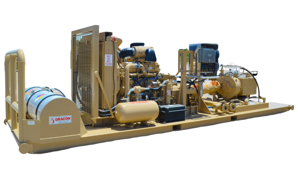
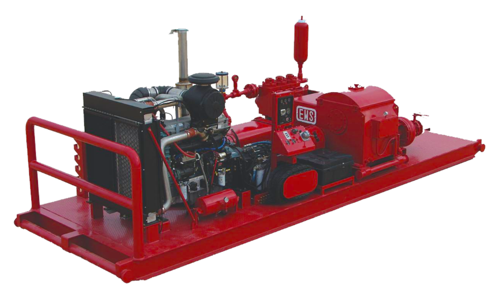
The surface pump for a single well or for just a few wells must be a high-head and low-specific-speed pump. Wide experience in the overall pumping industry has led to the use of positive-displacement pumps for this type of application, and triplex or quintuplex pumps, driven by gas engines or electric motors, power the vast majority of hydraulic pump installations. See Fig. 1.
Multiplex pumps consist of a power end and a fluid end. The power end houses a crankshaft in a crankcase. The connecting rods are similar to those in internal combustion engines, but connect to crossheads instead of pistons. The fluid end houses individual plungers, each with intake and discharge check valves usually spring loaded, and is attached to the power end by the spacer block, which houses the intermediate rods and provides a working space for access to the plunger system. Most units being installed in the oil field are of the horizontal configuration, which minimizes contamination of the crankcase oil with leakage from the fluid end. Vertical installations are still found, however, particularly with oil as the pumped fluid or when space is at a premium, as in townsite leases.
Multiplex pumps applied to hydraulic pumping usually have stroke lengths from 2 to 7 in. and plunger diameters between 1 and 2½ in. The larger plungers provide higher flow rates but are generally rated at lower maximum pressure because of crankshaft loading limitations. The normal maximum rating of multiplexes for continuous duty in hydraulic pumping applications is 5,000 psi, with lower ratings for the larger plungers, but applications above 4,000 psi are uncommon. Multiplex pumps are run at low speed to minimize vibration and wear and to avoid dynamic problems with the spring-loaded intake and discharge valves. Most applications fall between 200 and 450 rev/min, and because this is below the speeds of gas engines or electric motors, some form of speed reduction is usually required. Belt drives are found on some units, although gear reduction is more common while gear-reduction units are integral to some multiplexes and separate on others. A variety of reduction ratios are offered for each series of pumps. Because a positive-displacement pump has an essentially constant discharge flow rate for a given prime-mover speed, bypass of excess fluid normally is used to match a particular pressure and flow demand. Another option that has been used successfully is to drive the multiplex pump through a four-speed transmission, which greatly enhances the flexibility of the system. This allows much closer tailoring of the triplex output to the demand, thereby pumping at reduced speed when needed, which also tends to increase the life of such components as the packing and valving.
Each plunger pumps individually from a common intake manifold into a common discharge, and because discharge occurs only on the upstroke, there is some pulsation, for which pulsation dampers are commonly used.
Two types of plunger systems are in common use. For oil service, a simple and effective plunger-and-liner system is used that consists of a closely fitted metallic plunger inside a metallic liner. Sprayed metal coatings or other hard-facing means are often used to extend the life of the plunger and liner. When pumping water, the metal-to-metal system is not practical because the fit would have to be extremely close to keep leakage to an acceptable level. Galling and scoring are problems with close fits and the low lubricity of water, and to solve this problem, spring-loaded packing systems are used that do not require adjusting. The advent of high-strength aramid fibers for packing, in conjunction with other compounds to improve the friction characteristics, has resulted in a pronounced improvement in the ability of the pump to handle high-pressure water for extended periods of time. Water still presents a more severe challenge than oil, however, and water systems show much better life if operated at or below 3,500 psi.
Suction conditions are important to multiplex operation. Friction losses in piping, fluid end porting, and across the suction valving reduce the pressure available to fill the pumping chamber on the plunger downstroke, and if these losses are sufficiently great, cavitation may result. When pumping oil with dissolved gas, the reduction in pressure liberates free gas and causes knocking, so it is necessary to have a positive head on the suction side to overcome the friction losses. In addition, another phenomenon known as "acceleration head" must be considered. The flow in the suction piping must accelerate and decelerate a number of times for each crankshaft revolution. For the fluid (which has inertia) to follow the acceleration, energy must be supplied, which is then returned to the fluid on deceleration. The energy supplied during acceleration comes from a reduction in the pressure in the fluid, and if this drops too low, cavitation or gas liberation will result. The minimum suction head for the multiplex pump is then the sum of the friction losses and the acceleration head. Although the pump can draw a vacuum, this will flash gas and may tend to suck air across the valve or plunger packing. Manufacturers of multiplex pumps recommend appropriate suction charging pressures for their products, but it is worth noting that long, small-diameter suction lines increase the acceleration head loss and friction loss. It is therefore recommended for suction lines to be short and of large diameter, with no high spots to trap air or gas. Suction stabilizers or pulsation dampeners that tend to absorb the pulsations from the pump also reduce acceleration head, and users are encouraged to follow good piping practices in the installation of surface pumps.
In many cases, sufficient hydrostatic head is not available to provide the necessary suction pressure, and charge pumps are used to overcome this problem. Positive displacement pumps of the vane or crescent-gear type driven from the triplex have been used extensively, but they require a pressure-control valve to bypass excess fluid and match the multiplex displacement. Where electric power is available, centrifugal charge pumps have given excellent service. Centrifugal pumps generally need to run at speeds considerably above the multiplex speed, and so driving them from the multiplex presents problems, particularly with a gas engine drive where prime-mover speed variations cause significant variations in the charge-pump output pressure.
While good charging pressures are necessary to ensure proper loading and smooth operation, there are problems associated with very high charge pressures. These add to the crankshaft loading, and for charge pressures above about 250 psi, it is advisable to derate the maximum discharge pressure by one third of the charge pressure. High charge pressures also can adversely affect the lubrication of bearings, particularly in the crosshead wristpin. In addition, the mechanical efficiency of multiplex pumps is some 3 to 5% lower on the suction side compared to the discharge side.
In some cases, it is desirable to inject corrosion inhibitors or lubricants into the multiplex suction, and fresh water is sometimes injected to dissolve high salt concentrations. In severe pumping applications with low-lubricity fluids, lubricating oil is sometimes injected or dripped onto the plungers in the spacer block area to improve plunger life. Injection pumps are often driven from the multiplex drive for these applications. A troubleshooting guide for multiplex pumps is given in Table 1.
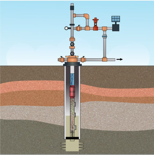
Various types of valves are used to regulate and to distribute the power fluid supply to one or more wellheads. Common to all free-pump systems is a four-way valve or wellhead control valve, which is mounted at the wellhead, as shown in Fig. 2. Its function is to provide for different modes of operation by shifting it to different positions. To circulate the pump into the hole, as shown in Fig. 3, power fluid is directed down the main tubing string. The power fluid begins to operate the pump once it is on bottom and seated on the standing valve. In the pump-out mode, power fluid is directed down the return tubing or casing annulus to unseat the pump and to circulate it to the surface. When the pump is on the surface, putting the valve in the bypass and bleed position permits the well to be bled down and the pump to be removed and replaced.
Most systems include a constant-pressure controller, as shown in Fig. 4, which maintains a discharge-pressure load on the multiplex pump by continuously bypassing the excess discharge fluid. It generally operates on the principle of an adjustable spring force on a piston-and-valve assembly that is pressure compensated. If the pressure rises on the high-pressure side, which is being controlled because of changing system loads, the pressure forces on the various areas within the valve will cause the valve to open and to bypass more fluid, restoring the high-pressure side to the preset condition. Jet pumps frequently are operated with a constant-pressure valve as the only surface control valve. The constant-pressure controller can be used to regulate the pressure on a manifold assembly serving multiple wells.
Reciprocating downhole pumps are usually regulated with a constant-flow control valve. The downhole unit can be maintained at a constant stroking rate if a constant volume of power fluid is supplied to it, and the constant-flow control valve is designed to provide a preset flow rate even if the downhole operating pressure fluctuated because of changing well conditions. Because this valve does not bypass fluid, it must be used with a constant-pressure controller on the higher-pressure or inlet side.
Where a number of wells are to be pumped from a central battery, a control manifold is used to direct the flows to and from the individual wells. Control manifolds are designed to be built up in modular fashion to match the number of wells being pumped and are generally rated for 5,000 psi working pressure. A constant pressure control valve regulates the pressure on the common power fluid side of the manifold. This pressure is generally a few hundred pounds per square inch greater than the highest pressure demanded by any well to allow proper operation of the individual well-control valves. Individual constant-flow control valves regulate the amount of power fluid going to each well. The use of a constant pressure valve allows excess fluid to bypass at the highest pressure. Meter loops or individual meters for each station can be integrated into the manifold.
Some wells flow or "kick back" when the operator is attempting to remove or insert a pump into the wellhead. Also, the presence of water may make it inadvisable to open up the entire tubing string for pump insertion and removal. The use of a lubricator allows the master valve below the wellhead to be closed, and the entire lubricator with the pump in it to be removed from the wellhead. The lubricator is essentially an extended piece of the tubing with a sideline to allow fluid flow when the pump is circulating in or out of the hole.
The function of the surface treating systems is to provide a constant supply of suitable power fluid to be used to operate the subsurface production units. The successful and economical operation of any hydraulic pumping system is to a large extent dependent on the effectiveness of the treating system in supplying high-quality power fluid. The presence of gas, solids, or abrasive materials in the power fluid adversely affects the operation and wears both the surface and downhole units. Therefore, the primary objective in treating crude oil or water for use as power fluid is to make it as free of gas and solids as possible. In addition, chemical treatment of the power fluid may be beneficial to the life of the downhole unit. In tests, it has been found that for best operation of the unit, a maximum total solids of 20 ppm, maximum salt content of 12 lbm/1,000 bbl oil, and a maximum particle size of 15 μm should be maintained. (These norms were established using oil in 30 to 40°API gravity range). It has been observed, however, that acceptable performance has been achieved in many cases where these values were exceeded, especially with the use of jet pumps and larger nozzles and throats. When using piston hydraulic pumps in heavy crude, these limitations have been exceeded and satisfactory results achieved, probably because the resulting wear does not increase leakage to the same degree. The periodic analysis of power fluid indicates steps to be taken for improved operation. For example, if the power-fluid analysis shows that iron sulfide or sulfate compounds make up the bulk of the solids, then a corrosion or scale problem exists that would require the use of chemical inhibitors to correct the problem. Water is the primary power fluid being used for jet pumping on offshore platforms and in applications where the majority of produced fluid being made is water. Water requires that a lubricant be added for use with reciprocating pumps. Other considerations in the choice of water or oil as a power fluid include:
Maintenance on surface pumps is usually less with the use of oil. The lower bulk modulus of oil also contributes to reduced pressure pulsations and vibrations that can affect all the surface equipment.
In high-friction systems, as sometime occurs with jet pumps in restricted tubulars, the lower viscosity of water can increase efficiency. With no moving parts, the jet pump is not adversely affected by the poor lubrication properties of water.
In deep casing-type installations, particularly with a jet pump, water when used as the power fluid can load up in the casing annulus return, negating any beneficial gas lifting effects for the produced gas.
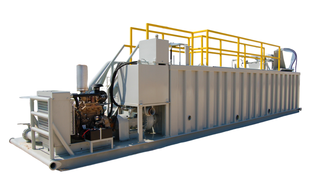
A typical power-oil treating system that has proved adequate for most OPF systems, when stock-tank-quality oil is supplied, is shown in Fig. 1. This system has the general characteristic that all return fluids from the well, both production and power fluid, must pass through the surface treating facility. The power-oil settling tank in this system is usually a 24-ft-high, three-ring, bolted steel tank. A tank of this height generally provides adequate head for gravity flow of oil from the tank to the multiplex pump suction. If more than one multiplex pump is required for the system, individual power-oil tanks can be set up for each pump, or a single large tank can be used, whichever is more economical and best meets the operating requirements. If a single large tank supplies the suction for several pumps, individual suction lines are preferable.
The location of the stock-tank take-off and level control is important because it establishes the effective settling interval of the power-oil tank and controls the fluid level. All fluid coming from the spreader rises to the stock take-off level, where stock-tank oil is drawn off. Fluid rising above this level is only that amount required to replace the fluid withdrawn by the multiplex pump, and it is in this region that the power-oil settling process takes place. The light solids settled out are carried with the production through the stock-tank take-off, and the heavier particles settle to the bottom, where they must be removed periodically. The location of the stock take-off point should be within 6 ft of the spreader. The height to which the stock oil must rise in the piping, to overflow into the stock tank, determines the fluid level in the power-oil tank. The diameter of the piping used should be sufficient to provide negligible resistance to the volume of flow required (4-in. minimum diameter recommended). The extension at the top of the level control is connected to the gas line to provide a vent that keeps oil in the power-oil tank from being siphoned down to the level of the top of the stock tank.
In the closed power-fluid system, the power fluid returns to the surface in a separate conduit and need not go through the surface production treating facilities. The consequent reduction in surface treating facilities can tend to offset the additional downhole cost of the system. Virtually all closed power-fluid systems are in California because of the large number of townsite leases and offshore platforms, and water is usually the power fluid. Gravity settling separation in the power-fluid tank ensures that the power fluid remains clean despite the addition of solids from power-fluid makeup, corrosion products, and contamination during pump-in and pump-out operations. The power-fluid makeup is required to replace the small amount of fluid lost through fits and seals in the downhole pump and wellhead control valve. A certain amount of power fluid is also lost during circulating operations as well.
Allis, D.H. and Capps, W.M. 1984. Submersible Pumping - Long Beach Unit of East Wilmington Field: A 17-Year Review. J Pet Technol 36 (8): 1321-1325. SPE-12200-PA. http://dx.doi.org/10.2118/12200-PA.
Christ, F.C. and Petrie, H.L. 1989. Obtaining Low Bottomhole Pressures in Deep Wells With Hydraulic Jet Pumps. SPE Prod Eng 4 (3): 290-294. SPE-15177-PA. http://dx.doi.org/10.2118/15177-PA.
Corteville, J.C., Ferschneider, G., Hoffmann, F.C. et al. 1987. Research on Jet Pumps for Single and Multiphase Pumping of Crudes. Presented at the SPE Annual Technical Conference and Exhibition, Dallas, Texas, 27-30 September 1987. SPE-16923-MS. http://dx.doi.org/10.2118/16923-MS.
Divine, D.L. 1979. A Variable Speed Submersible Pumping System. Presented at the SPE Annual Technical Conference and Exhibition, Las Vegas, Nevada, 23-26 September 1979. SPE-8241-MS. http://dx.doi.org/10.2118/8241-MS.
Foley, W.L. and Svinos, J.G. 1989. Expert Adviser Program for Rod Pumping (includes associated paper 19367). J Pet Technol 41 (4): 394-400. SPE-16920-PA. http://dx.doi.org/10.2118/16920-PA.
Gault, R.H. 1987. Designing a Sucker-Rod Pumping System for Maximum Efficiency. SPE Prod Eng 2 (4): 284-290. SPE-14685-PA. http://dx.doi.org/10.2118/14685-PA.
Gaymard, B., Chanton, E., and Puyo, P. 1988. The Progressing Cavity Pump in Europe: Results and New Developments. Presented at the Offshore South East Asia Show, Singapore, 2-5 February 1988. SPE-17676-MS. http://dx.doi.org/10.2118/17676-MS.
Gibbs, S.G. 1977. A General Method for Predicting Rod Pumping System Performance. Presented at the SPE Annual Fall Technical Conference and Exhibition, Denver, Colorado, 9-12 October 1977. SPE-6850-MS. http://dx.doi.org/10.2118/6850-MS.
Gibbs, S.G. 1982. A Review of Methods for Design and Analysis of Rod Pumping Installations. J Pet Technol 34 (12): 2931-2940. SPE-9980-PA. http://dx.doi.org/10.2118/9980-PA.
Gipson, F.W. and Swain, H.W. 1984. The Beam Pumping Design Chain. Proc., Annual Meeting of Southwestern Petroleum Short Course, Lubbock, Texas, 296–383.
Gosline, J.E. and O"Brien, M.P. 1942. The Water Jet Pump. In University of California Publications in Engineering, Vol. 3 (3), 167. Berkeley, California: The University Press.
Grupping, A.W., Coppes, J.L.R., and Groot, J.G. 1988. Fundamentals of Oilwell Jet Pumping (includes associated papers 17106 and 17113 ). SPE Prod Eng 3 (1): 9-14. SPE-15670-PA. http://dx.doi.org/10.2118/15670-PA.
Jiao, B., Blais, R.N., and Schmidt, Z. 1990. Efficiency and Pressure Recovery in Hydraulic Jet Pumping of Two-Phase Gas/Liquid Mixtures. SPE Prod Eng 5 (4): 361-364. SPE-18190-PA. http://dx.doi.org/10.2118/18190-PA.
Juch, A.H. and Watson, R.J. 1969. New Concepts in Sucker-Rod Pump Design. J Pet Technol 21 (3): 342-354. SPE2172-PA. http://dx.doi.org/10.2118/2172-PA.
Kramer, M.J.C., Martin, J.D., and Neely, A.B. 1982. Onsite Analysis of Sucker Rod Pumping Wells. Presented at the SPE Annual Technical Conference and Exhibition, New Orleans, Louisiana, 26-29 September 1982. SPE-11037-MS. http://dx.doi.org/10.2118/11037-MS.
Lea, J.F. and Bearden, J.L. 1982. Effect of Gaseous Fluids on Submersible Pump Performance. J Pet Technol 34 (12): 2922-2930. SPE-9218-PA. http://dx.doi.org/10.2118/9218-PA.
Lea, J.F. and Bearden, J.L. 1982. Gas Separator Performance for Submersible Pump Operation. J Pet Technol 34 (6): 1327-1333. SPE-9219-PA. http://dx.doi.org/10.2118/9219-PA.
Lea, J.F. and Bowen, J.F. 1992. Dynamic Measurements of Beam-Pump Parameters. SPE Prod Eng 7 (1): 113-120. SPE-18187-PA. http://dx.doi.org/10.2118/18187-PA.
Lubinski, A. and Blenkarn, K.A. 1957. Buckling of Tubing in Pumping Wells, Its Effects and Means for Controlling It. In Transactions of the American Institute of Mining, Metallurgical, and Petroleum Engineers, Vol. 210, 73–88. Dallas, Texas: Society of Petroleum Engineers.
McCoy, C.D. and Ross, K. 1992. Plunger Lift and Economic Alternative to Sucker-Rod Pumps, Proc., Southwestern Petroleum Short Course, Lubbock, Texas, 337.
Neely, A.B. and Tolbert, H.O. 1988. Experience With Pumpoff Control in the Permian Basin. J Pet Technol 40 (5): 645-649. SPE-14345-PA. http://dx.doi.org/10.2118/14345-PA.
Neely, A.B. and Patterson, M.M. 1984. Soft Start of Submersible Pumped Oil Wells. J Pet Technol 36 (4): 653-656. SPE-11042-PA. http://dx.doi.org/10.2118/11042-PA.
Nelson, C.C. 1975. The Jet Free Pump-Proper Application Through Computer Calculated Operating Charts. Presented at the Southwestern Petroleum Short Course, Lubbock, Texas.
Nolen, K.B. and Gibbs, S.G. 1973. Subsurface Hydraulic Pumping Diagnostic Techniques. Presented at the Fall Meeting of the Society of Petroleum Engineers of AIME, Las Vegas, Nevada, 30 September-3 October 1973. SPE-4540-MS. http://dx.doi.org/10.2118/4540-MS.
Saveth, K.J. and Klein, S.T. 1989. The Progressing Cavity Pump: Principle and Capabilities. Presented at the SPE Production Operations Symposium, Oklahoma City, Oklahoma, 13-14 March 1989. SPE-18873-MS. http://dx.doi.org/10.2118/18873-MS.
Schmidt, Z. and Doty, D.R. 1989. System Analysis for Sucker-Rod Pumping. SPE Prod Eng 4 (2): 125-130. SPE-15426-PA. http://dx.doi.org/10.2118/15426-PA.
Stewart, R.E. 1980. The Effects of Power Supply Integrity on Electric Submergible Pumping Systems. Presented at the SPE Rocky Mountain Regional Meeting, Casper, Wyoming, 14-16 May 1980. SPE-9038-MS. http://dx.doi.org/10.2118/9038-MS.
Swaim, H.W. and Hein, N.W. 1987. Surface Dynamometer Card Interpretation: A Beam-Pumping Problem-Solving Tool. Presented at the Southwestern Petroleum Short Course, Lubbock, Texas.
Wilson, P.M. 1973. Jet Pump—A Progress Review on Two Years of Field Performance. Presented at the Southwestern Petroleum Short Course, Lubbock, Texas.
The normal ESP system configuration is shown in Fig. 13.1. It shows a tubing-hung unit with the downhole components comprising of a multistage centrifugal pump with either an integral intake or separate, bolt-on intake; a seal-chamber section; and a three-phase induction motor, with or without a sensor package. The rest of the system includes a surface control package and a three-phase power cable running downhole to the motor. Because of the ESP’s unique application requirement in deep, relatively small-bore casings, the equipment designer and manufacturer are required to maximize the lift of the pump and the power output of the motor as a function of the diameter and length of the unit. Therefore, the equipment is typically long and slender. The components are manufactured in varying lengths up to approximately 30 ft, and for certain applications, either the pump, seal, or motor can be multiple components connected in series.
Throughout their history, ESP systems have been used to pump a variety of fluids. Normally, the production fluids are crude oil and brine, but they may be called on to handle liquid petroleum products; disposal or injection fluids; and fluids containing free gas, some solids or contaminates, and CO2 and H2S gases or treatment chemicals. ESP systems are also environmentally esthetic because only the surface power control equipment and power cable run from the controller to the wellhead are visible. The controller can be provided in a weatherproof, outdoor version or an indoor version for placement in a building or container. The control equipment can be located within the minimum recommended distance from the wellhead or, if necessary, up to several miles away. API RP11S3 provides the guidelines for the proper installation and handling of an ESP system. Table 13.1, some of which are discussed later in this chapter.
The ESP is a multistage centrifugal type. A cross section of a typical design is shown in Fig. 13.2. The pumps function is to add lift or transfer pressure to the fluid so that it will flow from the wellbore at the desired rate. It accomplishes this by imparting kinetic energy to the fluid by centrifugal force and then converting that to a potential energy in the form of pressure.
In order to optimize the lift and head that can be produced from various casing sizes, pumps are produced in several diameters for application in the most common casing sizes. Table 13.2 lists some common unit diameters, flow ranges, and typical casing sizes in which they fit.
Shaft. The shaft is connected to the seal-chamber section and motor by a spline coupling. It transmits the rotary motion from the motor to the impellers of the pump stage. The shaft and impellers are keyed, and the key transmits the torque load to the impeller. As was mentioned earlier, the diameter of the shaft is minimized as much as possible because of the restrictions placed on the pump outside diameter. Therefore, there are usually several shaft material options available, depending on the maximum horsepower (HP) load and corrosion protection required.
Housing. The housing is the pressure-containing skin for the pump. It holds and aligns all the components of the pump. There are several material options available for different application environments. For additional corrosion protection, there are several coatings that can be applied.
Several different styles of intakes can be selected. They allow for entrance of the fluid into the bottom of the pump and direct it into the first stage. Integral intakes can be threaded directly into the bottom of the housing during the manufacturing assembly process, while others are separate components, which are bolted on to the bottom pump flange.
A standard intake has intake ports that allow fluid to enter the pump. It is used when the fluid is all liquid or has a very low free-gas content. The intake shown in Fig 13.2 would be a standard intake if the reverse-flow screen were omitted.
A reverse-flow intake is used when the free-gas content in the fluid is high enough to cause pump-performance problems. The pump in Fig. 13.2 is shown with a reverse-flow design. The produced fluid with free gas flows up the outside of the reverse-flow intake screen, makes a 180° turn to enter through the perforations or holes at the top of the screen, flows back down to the intake ports and then back up to the first pump stage. These reversals in direction allow for a natural separation of the lighter gases from the liquid. The separated gas travels up the casing annulus and is vented at the wellhead. Another style is shown in the right-hand graphic of Fig. 13.3, which has a longer reversing path than does the inta


 8613371530291