
mud pump piston failure brands
Full traceability is provided with all products sold, including pistons. Traceability markings include: operators ID, packers ID, date of urethane pour, part number of piston, work order number, Made in USA brand, and SWOP logo.

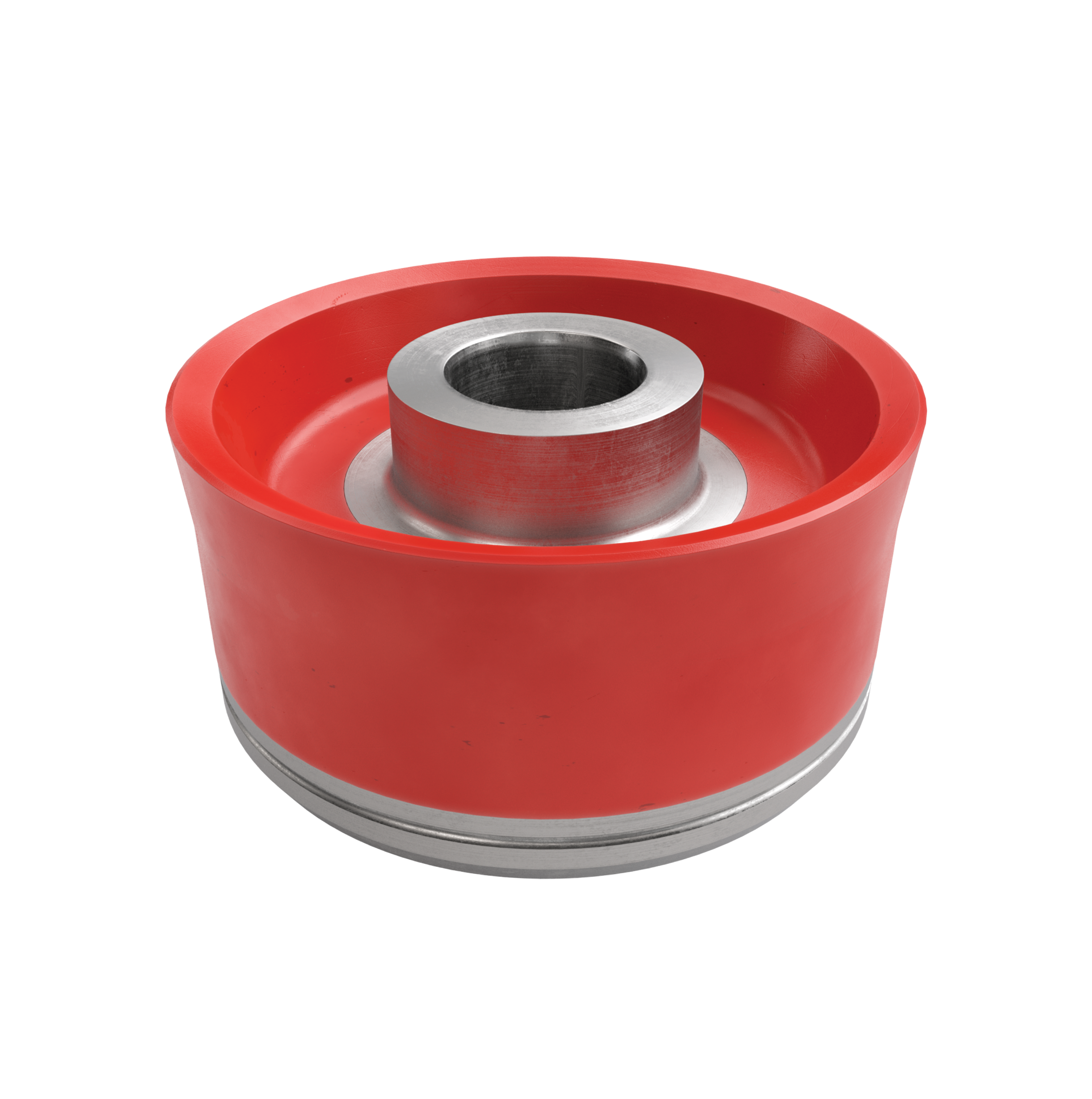
Tired of changing mud pump pistons? We have your solution. The TD will work in all types of drilling mud including oil based, synthetic and water based. It was specifically designed to work in applications where water based mud is used or in situations where WBM is used on the top side & OBM is used on the bottom end. This eliminates the need for changing the piston midway through the drilling program. The “TD” or “Total Depth” name reflects our commitment to make a single piston that will last from “spud” to “TD”. This piston has been engineered with a unique friction reducing material bonded into the urethane of the sealing lip. Because the TD is built to withstand friction in the liner, wear on your parts is minimized and savings is maximized. The Patriot™ TD is also designed to meet pressures of 7500 psi as well as temperatures up to 220 degrees.

Customers said they wanted long-lasting, easy-to-use pistons, and we delivered. Made from domestically sourced steel, GD Energy Products’ pistons feature proprietary bonded inserts and innovative geometry to deliver significantly longer life. This field proven design meets API Standards, and comes with our “Ready Inventory” promise that we’ll have it in stock, when you need it.
Our pistons, along with our new valves and seats, are designed for use in GD Energy Products PZ, F-Series, Bomco, HHA, Emsco and National 12P lines of triplex drilling pumps. Let GD Energy Products be your one-stop shop for your whole fleet of pumps.

Mud pump is the key equipment in drilling operation. If mud is compared to blood in drilling operation, mud pump is the heart of blood supply in drilling production. Therefore, its importance in drilling production is self-evident, and the spare parts of mud pump play a certain role in this.
Mud pump is a kind of machine which can transport mud or water to drill hole in the process of drilling. It is an important part of drilling equipment. Its main function is to inject mud into the well with the bit, cool the bit, clean the drilling tool, stabilize the well wall, drive the drilling, and bring the cuttings back to the ground after drilling.
In the normal circulation drilling, the mud pump is to send the surface flushing medium - clear water, mud or polymer flushing liquid under a certain pressure through the high-pressure hose, faucet and the center hole of drill string directly to the bottom of the drill bit, so as to cool the drill bit, remove the cuttings and transport them to the surface. The mud pump is driven by the power machine to rotate the crankshaft of the pump. The crankshaft drives the piston to do reciprocating motion in the pump cylinder through the crosshead. Under the alternating action of the suction and discharge valves, the purpose of pressing and circulating the flushing fluid is realized. Different types of mud pumps are used in different cases to ensure the smooth proceeding of the drilling operation.
According to the use of the mud pump, the leakage of the valve box, the burning of the bearing and the abnormal noise are all frequent faults that affect the normal use of the mud pump. Therefore, careful study of the causes of the problem plays a key role in prolonging the service life of the mud pump. At this time, a certain amount of spare parts of the mud pump are needed.
In the process of using the mud pump, the equipment failures caused by specific reasons are different. Reasonable use and maintenance of the equipment can extend the service life of the equipment. At the same time, in strict accordance with the basic elements of normal operation of the drilling pump, "medium power, medium pump pressure, medium speed operation, tight, tight, leak tight, pump pressure does not fluctuate, temperature is normal, sound is normal", the operation can ensure the good operation of the equipment. Of course, it"s also important to find the right mud pump spare parts!

(1) The diesel engine speed of the main pump station is too low, the fuel supply is insufficient, and the supply pressure of the hydraulic system is too low;
(2) The hydraulic system of the mud pump supplied by the main pumping station is faulty or the pressure adjustment of the overflow valve in the system is low and the internal leakage is serious, and the supply pressure is insufficient;
(1) Increase the speed of the diesel engine at the main pump station (n is greater than or equal to 1500 r/min), increase the fuel supply of the motor, and increase the effective working pressure of the hydraulic system (above 10MPa);
(1) Reason analysis: the J-shaped sealing ring in the sealed box is damaged or the oil tank fills over the calibrated oil level, the oil fills too much, and the piston is loose or damaged.
(2) Solution: replace the J-shaped sealing ring in the sealed box, discharge the oil tank oil to the calibrated oil level; adjust the adjustment screw sleeve of the compression piston or replace the piston.
(1) Reason analysis: The diesel engine speed of the main pumping station is low and the fuel supply is insufficient, resulting in insufficient flow of the water pump and the pressure cannot rise.
(2) Solution: Increase the diesel engine speed of the main pump station (n is greater than or equal to 1500 r/min), increase the motor oil supply, increase the water pump flow, and then increase the pressure; unscrew the pressure gauge and fill the buffer with oil or After replacing the rubber diaphragm, fill it with engine oil.
The reasons and solutions for the failures that often occur in mud pump operations are listed above. The equipment failures caused by specific reasons in the use of mud pumps are different. Reasonable use and maintenance of the equipment can extend the service life of the equipment.

Mud pump manufacturers frequently offer both types of pumps. In reality, the pump power end and fluid ends are identical. The difference lies with the method used by the pump to displace the mud.
In the early 1990s, it was generally accepted that the pumps used on mid-size and small boring machines should deliver fluid to the bore at a high pressure (1,800 to 2,200 psi/124 to 152 bar)) and have a low flow rate of 5 to 25 gpm (19 to 95 Lpm).
As the industry matured and operators became more experienced, it was found that a higher mud flow with lower pressures was the superior way to bore. In some formations high pressure, low flow is still preferred and provides the most success. However, in the majority of areas, higher flows are best to provide hole cleaning (removal of solids) and provide adequate bentonite for formation sealing and lubrication.
One advantage of plungers/packing is that the packing can be adjusted by the operator to minimize leakage until the bore is complete and the pump can be serviced.
Pumps with piston/liner technology work in the opposite manner. Pistons work well to prevent leakage when flow pressures are low (below 1,200 psi/83 bar). Pistons are generally larger in diameter than plungers, allowing the pump to run slower-this is good-for the same flow rates.
Pistons have two disadvantages. First, when they fail or start leaking, the operator can do nothing to prolong operation until repairs can be made. Thus, repairs usually have to be made shortly after significant leakage starts. Second, pistons like to run cool and be lubricated. Thus, a piston cooling/lubrication system must be employed to add to piston life.
This system consists of a small centrifugal pump, spray nozzles, piping and collection tank. It sprays a mixture of water and lubricant (non-foaming soap or a small amount of liquid polymer), onto the back of the pistons.
Many boring machines are equipped with plunger pumps. These units are being applied where piston technology should be used, mainly low pressure and higher flows. These pumps frequently have leakage problems. To help operators combat leakage on these boring machines, conversion kits are being developed by some pump manufacturers to allow pumps to be changed from plunger to piston technology. Consult your boring machine or pump manufacturer for availability.
Economically, a good time to consider changing from plunger to piston technology on your pump is when the plungers are no longer serviceable and must be replaced. Conversion kits can be installed in the field and are considered bolt off bolt on upgrades.
If your mud pump has leakage problems, consider that you may be asking your pump to operate in a condition or application for which it was not originally designed.
The mud pump piston is a key part for providing mud circulation, but its sealing performance often fails under complex working conditions, which shorten its service life. Inspired by the ring segment structure of earthworms, the bionic striped structure on surfaces of the mud pump piston (BW-160) was designed and machined, and the sealing performances of the bionic striped piston and the standard piston were tested on a sealing performance testing bench. It was found the bionic striped structure efficiently enhanced the sealing performance of the mud pump piston, while the stripe depth and the angle between the stripes and lateral of the piston both significantly affected the sealing performance. The structure with a stripe depth of 2 mm and angle of 90° showed the best sealing performance, which was 90.79% higher than the standard piston. The sealing mechanism showed the striped structure increased the breadth and area of contact sealing between the piston and the cylinder liner. Meanwhile, the striped structure significantly intercepted the early leaked liquid and led to the refluxing rotation of the leaked liquid at the striped structure, reducing the leakage rate.
Mud pumps are key facilities to compress low-pressure mud into high-pressure mud and are widely used in industrial manufacture, geological exploration, and energy power owing to their generality [1–4]. Mud pumps are the most important power machinery of the hydraulic pond-digging set during reclamation [5] and are major facilities to transport dense mud during river dredging [6]. During oil drilling, mud pumps are the core of the drilling liquid circulation system and the drilling facilities, as they transport the drilling wash fluids (e.g., mud and water) downhole to wash the drills and discharge the drilling liquids [7–9]. The key part of a mud pump that ensures mud circulation is the piston [10, 11]. However, the sealing of the piston will fail very easily under complex and harsh working conditions, and consequently, the abrasive mud easily enters the kinematic pair of the cylinder liner, abrading the piston surfaces and reducing its service life and drilling efficiency. Thus, it is necessary to improve the contact sealing performance of the mud pump piston.
As reported, nonsmooth surface structures can improve the mechanical sealing performance, while structures with radial labyrinth-like or honeycomb-like surfaces can effectively enhance the performance of gap sealing [12–14]. The use of nonsmooth structures into the cylinder liner friction pair of the engine piston can effectively prolong the service life and improve work efficiency of the cylinder liner [15–17]. The application of nonsmooth grooved structures into the plunger can improve the performance of the sealing parts [18, 19]. The nonsmooth structures and sizes considerably affect the sealing performance [20]. Machining a groove-shaped multilevel structure on the magnetic pole would intercept the magnetic fluid step-by-step and slow down the passing velocity, thus generating the sealing effect [21–23]. Sealed structures with two levels or above have also been confirmed to protect the sealing parts from hard damage [24]. The sealing performance of the high-pressure centrifugal pump can be improved by adding groove structures onto the joint mouth circumference [25]. The convex, pitted, and grooved structures of dung beetles, lizards, and shells are responsible for the high wear-resistance, resistance reduction, and sealing performance [26–28]. Earthworms are endowed by wavy nonsmooth surface structures with high resistance reduction and wear-resistance ability [29]. The movement of earthworms in the living environment is very similar to the working mode of the mud pump piston. The groove-shaped bionic piston was designed, and the effects of groove breadth and groove spacing on the endurance and wear-resistance of the piston were investigated [30]. Thus, in this study, based on the nonsmooth surface of earthworms, we designed and processed a nonsmooth striped structure on the surface of the mud pump piston and tested the sealing performance and mechanism. This study offers a novel method for prolonging the service life of the mud pump piston from the perspective of piston sealing performance.
The BW-160 mud pump with long-range flow and pressure, small volume, low weight, and long-service life was used here. The dimensions and parameters of its piston are shown in Figure 1.
A striped structure was designed and processed on the contact surface between the piston cup and the cylinder liner. The striped structure was 5 mm away from the outermost part of the lip, which ensured the lip could contact effectively with the cylinder liner. Based on the structural dimensions of the piston cup, we designed a 2-stripe structure, and the very little stripe space affected the service life of the piston [30]. Thus, the stripe space of our bionic piston was set at 5 mm. According to the machining technology, two parameters of stripe depth h and the angle between the stripes and lateral of the piston α were selected (Figure 2).
A mud pump piston sealing performance test bench was designed and built (Figure 3). This bench mainly consisted of a compaction part and a dynamic detection part. The compaction part was mainly functioned to exert pressure, which was recorded by a pressure gauge, to the piston sealed cavity. This part was designed based on a vertical compaction method: after the tested piston and the sealing liquid were installed, the compaction piston was pushed to the cavity by revolving the handle. Moreover, the dynamic detection part monitored the real-time sealing situation and was designed based on the pressure difference method for quantifying the sealing performance. This part was compacted in advance to the initial pressure P0 (0.1 MPa). After compaction, the driving motor was opened, and the tested piston was pushed to drive the testing mud to reciprocate slowly. After 1 hour of running, the pressure P on the gauge was read, and the pressure difference was calculated as , which was used to measure the sealing performance of the piston.
To more actually simulate the working conditions of the mud pump, we prepared a mud mixture of water, bentonite (in accordance with API Spec 13A: viscometer dial reading at 600 r/min ≥ 30, yield point/plastic viscosity radio ≤ 3, filtrate volume ≤ 15.0 ml, and residue of diameter greater than 75 μm (mass fraction) ≤ 4.0%), and quartz sand (diameter 0.3–0.5 mm) under complete stirring, and its density was 1.306 g/cm³ and contained 2.13% sand.
The test index was the percentage of sealing performance improvement β calculated aswhere and are the pressure differences after the runs with the standard and the bionic pistons, respectively ().
The sealing performance tests showed the striped structures all effectively enhanced the contact sealing between the piston and the cylinder liner. In particular, the increase of sealing performance relative to the standard piston minimized to 21.05% in the bionic striped piston with a stripe depth of 3 mm and angle of 45° and maximized to 90.79% in the bionic striped piston with the stripe depth of 2 mm and angle of 90°. Range analysis showed the sealing performance of pistons was affected by the stripe depth h and angle α, and these two parameters (h and α) have the same effect on the sealing performance.
Figure 4 shows the effects of stripe depth and angle on the sealing performance of mud pump pistons. Clearly, the stripe depth should be never too shallow or deep, while a larger angle would increase the sealing performance more (Figure 4).
Sealing validity tests were conducted to validate the sealing performance of the bionic striped pistons. It was observed whether the sealing liquid would leak at the tail of the cylinder liner, and the time of leakage was recorded. The standard piston and the most effective bionic piston were selected to compare their sealing performances.
Both the standard piston and the bionic striped piston leaked, which occurred after 84 and 249 minutes of operation, respectively (Figure 5). Figure 6 shows the pressures of the two pistons during testing. Clearly, the sealing pressure of the standard piston declined rapidly before the leakage, but that of the bionic piston decreased very slowly. After the leakage, the reading on the pressure gauge in the standard piston declined to 0 MPa within very short time, but that of the bionic piston decreased much more slowly.
The beginning time of leakage was inconsistent between the standard and bionic pistons (84 minutes vs. 249 minutes). In order to compare the leakage of these two pistons, the leaked liquid was collected when the piston started to leak. The volume of the leaked liquid was measured using a graduated cylinder every 5 minutes from the 84th minute and 249th minute, respectively (both considered as 0 minute), for 20 minutes. Figure 7 shows the leaked amounts of the standard piston and the bionic piston. Clearly, after the leakage and failure, the leaking speed and amount of the bionic piston were both smaller than those of the standard piston.
The piston lips and the cylinder liner were under interference contact, and their mutual extrusion was responsible for the lip sealing. Thus, a larger pressure between the piston lips and the cylinder liner reflects a higher lip sealing effect.
The bionic striped piston with the highest sealing performance (h = 2 mm, α = 90°) was selected for the sealing mechanism analysis and named as the bionic piston. The 3D point cloud data of standard piston were acquired by using a three-dimensional laser scanning system (UNIscan, Creaform Inc., Canada). Then, the standard piston model was established by the reverse engineering technique. The striped structure of the bionic piston was modeled on basis of the standard piston.4.1.1. Contact Pressure of Piston Surface
The standard piston and the bionic piston were numerically simulated using the academic version of ANSYS® Workbench V17.0. Hexahedral mesh generation method was used to divide the grid, and the size of grids was set as 2.5 mm. The piston grid division is shown in Figure 8, and the grid nodes and elements are shown in Table 3. The piston cup was made of rubber, which was a hyperelastic material. A two-parameter Mooney–Rivlin model was selected, with C10 = 2.5 MPa, C01 = 0.625 MPa, D1 = 0.3 MPa−1, and density = 1120 kg/m3 [32, 33]. The loads and contact conditions related to the piston of the mud pump were set. The surface pressure of the piston cup was set as 1.5 MPa, and the displacement of the piston along the axial direction was set as 30 mm. The two end faces of the cylinder liner were set as “fixed support,” and the piston and cylinder liner were under the frictional interfacial contact, with the friction coefficient of 0.2.
Figure 9 shows the pressure clouds of the standard piston and the bionic piston. Since the simulation model was completely symmetrical and the pressures at the same position of each piston were almost the same, three nodes were selected at the lip edge of each piston for pressure measurement, and the average of three measurements was used as the lip edge pressure of each piston. The mutual extrusion between piston and cylinder liner happened at the lip, and thereby the larger of the lip pressure was, the better the sealing performance was. The lip pressure of the standard piston was smaller than that of the bionic piston (2.7371 ± 0.016 MPa vs. 3.0846 ± 0.0382 MPa), indicating the striped structure enhanced the mutual extrusion between the bionic piston and the cylinder liner and thereby improved the sealing performance between the lips and the cylinder liner. As a result, sand could not easily enter the piston-cylinder liner frictional interface, which reduced the reciprocated movement of sand and thereby avoided damage to the piston and the cylinder liner.
Figure 10 shows the surface pressures from the lip mouth to the root in the standard piston and the bionic piston. The surface pressure of the bionic piston surpasses that of the standard piston, and the pressure at the edge of each striped structure changes suddenly: the pressures at the striped structure of the bionic piston are far larger than at other parts. These results suggest the contact pressure between the edges of the striped structures and the cylinder liner is larger, and the four edges of the two striped structures are equivalent to a four-grade sealed lip mouth formed between the piston and the cylinder liner, which generates a multilevel sealing effect and thereby largely enhances the sealing effect of the piston.
The piston surface flow field was numerically simulated using the CFX module of the software ANSYS® Workbench V17.0. The side of the lips was set as fluid inlet, and the other side as fluid outlet, as shown in Figure 11. The inlet and outlet were set as opening models, and the external pressure difference between them was 0 Pa. The moving direction of the piston was opposite to the fluid flow direction. The fluid region was divided into grids of 0.2 mm, while the striped structures were refined to grade 2.
Figures 12 and 13 show the surface streamline clouds and sectional streamline clouds of the two pistons at the early stage of leakage when the fluid entered the interface. Clearly, compared with the standard piston, when the surface-leaked liquid from the bionic piston passed the striped structure, the streamlines were sparse and significantly decreased in number, and the flow velocity declined more. The flow velocity decreased from 0.9348 m/s to 0.7555 m/s in the bionic piston and from 0.9346 m/s to 0.9262 m/s in the standard piston. It shows that, after the blockage by the striped structures, the striped structure more significantly intercepted the leaked liquid and could reduce the leakage rate of the piston, thereby enhancing the sealing effect.
Figure 13 shows the section leakage streamline of the standard piston and the bionic piston. Clearly, compared with the standard piston, when the leaked liquid of the bionic piston flowed through the striped structures, the streamlines would reflux and reverse inside the striped structures, indicating the striped structures can efficiently store the leaked liquid and slow down the leakage.
To better validate the sealing mechanism of the bionic striped pistons, a piston’s performance testing platform was independently built and the sealed contact of the pistons was observed. A transparent toughened glass cylinder liner was designed and machined. The inner diameter and the assembly dimensions of the cylinder liner were set according to the standard BW-160 mud pump cylinder liners. The sealing contact surfaces of the pistons were observed and recorded using a video recorder camera.
Figure 14 shows the surface contact of the standard piston and the bionic piston. Clearly, in the contact areas between the standard piston and the cylinder liner, only the narrow zone at the lip mouth contacted, as the contact width was only 4.06 mm. On the contrary, the contact areas between the bionic piston and the cylinder liner were all very wide, as the contact width was about 18.36 mm, and the sealed area was largely enlarged (892.8 mm2 vs. 4037.6 mm2) according to the contact areas calculated, which were favorable for improving the sealing performance.
Figure 15 shows the oil film left after the piston running. The oil film width of the bionic piston was far larger than that of the standard piston (20.48 mm vs. 2.28 mm). The striped structure of the bionic piston could store the lubricating oils, and uniform oil films were formed after its repeated movement, which reduced the friction between the piston and the cylinder liner, so that the seal failure of the piston would not happen due to excessive abrasion.
(1)The bionic striped structure significantly enhanced the sealing performance of the mud pump pistons. The stripe depth and the angle between the stripes and the piston were two important factors affecting the sealing performance of the BW-160 mud pump pistons. The sealing performance was enhanced the most when the stripe depth was 2 mm and the angle was 90°.(2)The bionic striped structure can effectively enhance the contact pressure at the piston lips, enlarge the mutual extrusion between the piston and the cylinder liner, reduce the damage to the piston and cylinder liner caused by the repeated movement of sands, and alleviate the abrasion of abrasive grains between the piston and the cylinder liner, thereby largely improving the sealing performance.(3)The bionic striped structure significantly intercepted the leaked liquid, reduced the leakage rate of pistons, and effectively stored the leaked liquid, thereby reducing leakage and improving the sealing performance.(4)The bionic striped structure led to deformation of the piston, enlarged the width and area of the sealed contact, the stored lubricating oils, and formed uniform oil films after repeated movement, which improved the lubrication conditions and the sealing performance.
The bionic striped structure can improve the sealing performance and prolong the service life of pistons. We would study the pump resistance in order to investigate whether the bionic striped structure could decrease the wear of the piston surface.

The 2,200-hp mud pump for offshore applications is a single-acting reciprocating triplex mud pump designed for high fluid flow rates, even at low operating speeds, and with a long stroke design. These features reduce the number of load reversals in critical components and increase the life of fluid end parts.
The pump’s critical components are strategically placed to make maintenance and inspection far easier and safer. The two-piece, quick-release piston rod lets you remove the piston without disturbing the liner, minimizing downtime when you’re replacing fluid parts.
Or maybe you’re going to be using a pressure washer for lower-pressure applications? Washing the sides of your house? Washing the family car? Washing the mud off your kids in the backyard—okay, that one is probably a criminal act, so don’t do it. Soft washing your roof?
Different types of pumps have different applications they work best for. The text below describes the differences and similarities between types of pumps, and the different applications each is best suited for.
For the most part, these two types of pumps function the same way. Both are reciprocating positive displacement pumps which pull water through an intake valve and into a chamber and push it—pressurized—back out through an outflow valve. These valves are engineered to be one-way only, meaning the intake valve will only open under negative pressure and the outflow valve will only open under positive pressure.
Duplex pumps have two pistons or plungers while triplex pumps contain three. This means duplex pumps must move faster to generate the same pressure levels as triplex pumps, consequently wearing their parts faster, and often causing a pulsating effect.
Triplex pumps last longer because each individual component has to do less work. Furthermore, the flow of water from triplex pumps is more constant, lessening the components’ strain even more.
Plunger pumps use a reciprocating plunger to pressurize water and force it through the outlet valve. The plunger is normally made out of hard ceramic, which is very durable and resistant to wear.
Similar to plunger pumps, piston pumps use reciprocating pistons to pressurize water and force it through the outlet valve. The difference between a piston and plunger pumps is the high-pressure seal. In a piston pump, the seal is attached to and reciprocates along with the piston.
Because of this, piston pump seals wear out faster and cannot handle as much pressure compared to plunger pumps. As the seal wears out, the power washer will suffer from reduced pressure buildup, resulting in a weakened stream and inefficient operation.
Pump failure is rarely the cause of power washer problems. The leading causes of pressure washer problems are system restrictions, which cause the pump to fail.
If the inlet hose or valve is not getting enough water to the pump, air is sucked in—this is called cavitation. When this mixture of water and air bubbles is pressurized it creates small explosions, damaging the pump and its components.
The easiest way to combat cavitation is to install a quality inlet valve and filter. This is especially true if the inlet source is a water tank, where many larger particles may sit and settle. If you are using particulates, such as sand, to assist with surface cleaning, make sure to use an appropriately-sized filter mesh to prevent clogging; you must also make sure your pressure washer has enough power to make sure the sand does not wash back into the machine, whereby ruining the pump.
Taken care of properly, with regular maintenance checkups, your pressure washer pump should last at least as long as the hour-rating it’s supposed to last for as per the owner’s manual. As we’ve said, actual pump failure is rarely the cause of the problem, but rather the result. Give us a call or submit a contact form with your questions, and we’ll do our very best to give you the right answer.

Since the modern mud (or slush) pump was built approximately 60 years ago, the industry has widely accepted the three cylinder or triplex style pump. Triplex mud pumps are manufactured worldwide, and many companies have emulated the original design and developed an improved form of the triplex pump in the past decade.
As in all single acting pumps, the piston exerts a load on the crankshaft. The load is then transmitted to the crankshaft main bearings, which are set in their retainers in the pump frame or housing (see Figure 2).
The middle piston often exerts seven times greater bending moment on the crankshaft than either of the outer two pistons, causing the crankshaft to bend or flex. Where the force is directed along either of the outer two piston rods to their respective outer two crankshaft cams, the force is close to the bearings and the bending moment is considerably less. However, when the center piston is under pressure and the forces are directed down the middle connecting rod to the central cam, the distance of that central cam from either main bearing is large (sometimes 850 mm or 33 in), thus allowing for a large bending moment and resulting in significant flex in the crankshaft.
That the crankshaft is subjected to extreme bending loads and stress concentration areas is one of the drawbacks of the triplex design. Experience shows that all triplex pumps eventually exhibit crankshaft cracking if the operator is using the pump at higher loads and pressures, which is now common as drilling contractors are facing deeper, longer sections to drill. In the past, drillers rarely pushed the performance limitations of triplex pumps; 5,000 psi rated pumps were usually only operated at a maximum of 2,800 psi 90 percent of the time. Now contractors are encouraged to run pumps at the much higher pressures around 4,300 psi, only leaving a safety margin below the pressure relief valve setting. This means the crankshaft is subjected to extended maximum load, which inevitably shortens time to failure, probably exponentially.
Some may suggest that an increase in the number of pistons to improve flow rate will also reduce piston load. Although the middle piston load may be reduced for the same overall pump horsepower, the distance from the main bearings to the middle cam increases, which is not advantageous. For example, a five cylinder pump with the middle cam 50 in from the main bearing will have the same bending moment as a triplex with a 30 in middle cam to bearing distance. However, installing bearings close to the cams can reduce the cyclic failure problems on any pump.
For the drilling industry, the problem with this design is that few have managed to design a crankshaft where bearings can be installed anywhere other than at the crankshaft ends. Consequently, most pumps currently available have crankshafts unsupported close to the middle cam. With the middle area of the crankshaft unsupported, crankshaft failure is inevitable.
A triplex pump with a large load acting on the middle of the crankshaft of approximately 120,000 lbs and a typical distance of about 30 in from middle cam to either main bearing will exert a bending moment of 300,000 lb-ft on the crankshaft adjacent to the main bearing. If the bearing is not spherical, the bending moment where the shaft meets the bearing will coincide with the point on the shaft that the crank can no longer bend because it is restricted by the fixed bearing, which creates huge stress concentration. That load comes and goes cyclically every revolution of the pump. If the pump is rotating at 100 rpm or strokes, then in one week of drilling the crank will experience one million cycles of 300,000 lb-ft effectively switching on and off.
A spherical bearing solves this problem and will not contribute to crankshaft failure. Spherical bearings allow the crankshaft to have a wave and flex without restraining the shaft and giving rise to stress concentration or shear (see Figure 5).
Another symptom of crankshaft deflection or bending is abnormal main gear wear patterns. The high unsupported load in the middle of the crankshaft effectively bows the shaft and consequently the bull gear is moved off alignment, and a strange wear pattern may appear on the gears. Although this is an undesirable occurrence, it is of little importance compared with crankshaft failure. It does explain abnormal wear on a pump used continuously at high pressure.
A pump that addresses these issues may be the solution. A quadraplex has minimal bending moments due to the close proximity of the main bearings to every cam (see Figure 7).
A fully assembled crankshaft is the best and only way to install multiple bearings close to the cams. Even though there is minimal flexure in this design, spherical bearings eliminate stress concentration or point loading. With cam to bearing distances no more than 10 in, the bending moment on a quadraplex crankshaft will be one quarter that of the triplex or five cylinder pump.
In an environment where few advances have been made in mud pump technology in the last 50 years, designers in the mud pump sector of the drilling industry can develop workable solutions to the problems and limitations inherent in triplex pumps.
The future of mud pump design will involve a solution to excessive crankshaft bending moments and address other needed areas of improvement, including piston speed, module replacement in the field, quality of discharge pressure and smoothness of flow-all combined with ease of transportation.

Drilling consumables such as mud pump systems and their components can drastically increase your uptime while reducing costs and health/safety/environmental (HSE) risks. To support your drilling needs, Forum’s patented P-Quip® mud pump system offers a single-source solution that integrates high-quality fluid end components for maximum longevity and performance.
With more than 20 years of successful operation in severe environments, P-Quip offers a proven track record for the lowest cost of ownership in the industry. As part of our commitment to quality, our mud pump parts use patented Banded Bore™ technology that significantly reduces stress concentrations and leads to longer module life.
FET manufactures a full range of valves and seats for every drilling and well-servicing application as part of our full line of Osprey® mud pump system solutions. All of our valves and seats can be used in water, water base, oil base and synthetic base mud applications. FET offers additional valves and seats not listed below, including drilling valves, frac valves and well service valves. FET’s QC standards for the dimensional and material specs are extremely rigid in comparison to other manufacturers. Contact your FET representative to learn more.


 8613371530291