
mud pump pressure formula for sale
Rig pump output, normally in volume per stroke, of mud pumps on the rig is one of important figures that we really need to know because we will use pump out put figures to calculate many parameters such as bottom up strokes, wash out depth, tracking drilling fluid, etc. In this post, you will learn how to calculate pump out put for triplex pump and duplex pump in bothOilfield and Metric Unit.

NOTE: Max RPM in the above equation varies according to type of pump, size of stroke, and other variables. Duplex pumps often run about 100 RPM Max. while triplex pumps will run somewhere between 100 RPM Max and 400 RPM Max.
I have a reciprocating pump and I know what my max rated rod load is (in foot pounds). I also know what size plunger size my pump has. What PSI will my pump produce?
Specific Gravity is used when sizing a centrifugal pump. Liquids with a specific gravity greater than 1.0 are heavier than water and conversely, liquids with a specific gravity lower than 1.0 are lighter weight than water and will generally float on water.
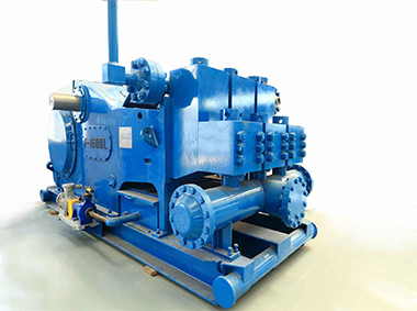
Pivotal to drilling and production, multiplex drilling pumps for sale have increased operational efficiency through the ability to ferry large volumes of fluid. At the heart of the quintuplex drilling pump developed by ShalePumps, lies a design that exploits the output of additional cylinders to curb pulsation variance.
Packed into physically smaller dimensions, the power packed quintuplex drilling pump assures a steady flow at the surface. With proven reliability, the quintuplex pump keeps the fluid in circulation, maintaining optimal pressure and volume, fetching debris effortlessly from the wellbore.
The featured quintuplex drilling pump combines structural superiority and engineering knowhow for enhanced life expectancy in continuous operations. Additionally, Measurement While Drilling (MWD) and Logging While Drilling (LWD) operations are substantially improved by the increased data transfer rate bandwidth.
The design accomplishes the added objective of extending life of downhole tools through operational precision of the quintuplex drilling pump. Improved rate of flow helps in cutting overall costs, dispensing with the need for many pumps. ShalePumps, possessing the technical expertise with an extensive range of proven solutions, takes great care to incorporate high quality components in every quintuplex drilling pump. The crankshafts, piston rods, liners, connecting rods, bearings etc are all of the highest quality. Each quintuplex drilling pump, despite the composition of high wear components, is guaranteed to offer longer continuous life.
ShalePumps is proud to bring the quintuplex design to a new level. Built to be smaller, lighter and smoother than any conventional triplex design. The addition of a fourth and fifth cylinder decreases pulsation variance to a minimal level. This increases accuracy and precision during LWD and MWD applications and increases the life expectancy of down-hole tools.

Density of the Kick, ppg = initial mud weight, ppg – (initial stabilized drillpipe pressure, psi – initial stabilized casing pressure, psi)/(0.052 x Length of the kick, ft)
Riser margin is = (drilling fluid gradient to control the formation pressure with riser, psi/ft x depth of the hole (TVD), ft – seawater gradient, psi/ft

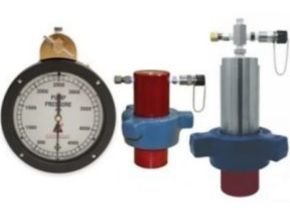
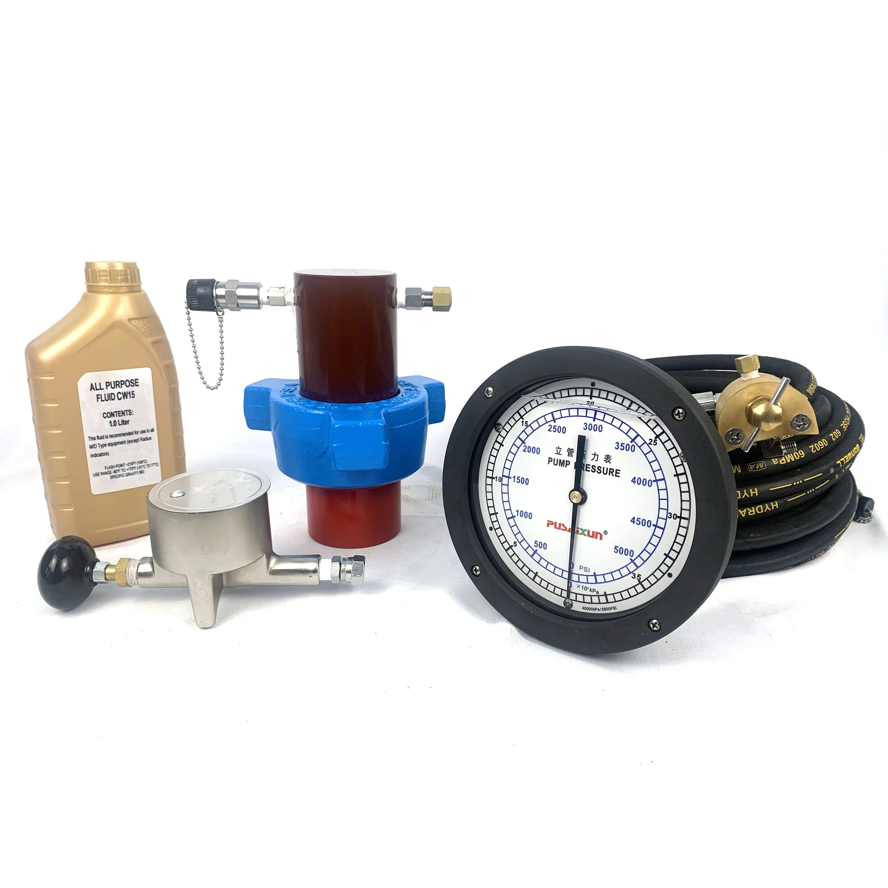
RIGCHINA Stand Pipe Gauges provide a quick, accurate display of pump pressure. Main applications are for standpipes and to be mounted on mud pumps. This style of gauge has been in service for many years and has proven to be a tough, dependable and reliable way to monitor pump pressure.

We provide hydraulic components & repair services for industrial applications like paper mills, saw mills, steel mills, recycling plants, oil & gas applications and mobile applications, including construction, utility, mining, agricultural and marine equipment. This includes hydraulic pumps, motors, valves, servo/prop valves, PTOs, cylinders & parts.

The discharge pressure of a pump is commonly referred to as head or pressure, but head and pressure are not the same across all liquids. It often causes confusion leading to a miscalculation of the correct pump specification to use.
What is pressure?Pressure is fluid dependent and relative to fluid density. A calculation of the pressure will change according to the fluid’s specific gravity.
Manometers on pumps indicate suction and delivery pressures, and the corresponding differential pressure, which does not take into account the specific gravity of the fluid being pumped meaning any readings provided need to be checked against the fluids specific gravity to calculate the differential pressure being produced.
The absorbed power is the power consumed by the pump during operation at the required duty point. Although a pump may be fitted with a larger motor than is required for the duty, the power absorbed is usually indicated on the pump curve with an intersecting line of where the pump is expected to perform.
The density and pressure directly affect the power absorbed by the motor during operation. The amount of power absorbed by a motor during operation is multiplied by the SG to calculate the power absorbed.
As a pump operates according to the system it is installed in, care will need to be taken to ensure the absorbed power at the highest point of the curve is larger than the density multiplied by the SG.
In the above example, the highest point is 7.5Kw so for water (7.5Kw x 1) max absorbed power will be 7.5Kw, and for a fluid, with a density of 1.3, the maximum absorbed power would be 7.5Kw x 1.3sg = 9.75Kw. A motor greater than 10Kw would be advisable. Read more about why a pump may be fitted with a larger motor.
Head loss refers to the pressure loss (friction) imparted on a fluid as it travels through components in a system. All parts from straight pieces of pipe, to bends, valves, heat exchangers and couplings create different levels of friction loss.
Different angled bends such as 45° bend compared to a 90° will create different levels of loss in a system. Each item has a pressure loss value known as a K factor detailing the losses caused by each part.
Geodetic HeadThis is the physical difference in height between the liquid level and the highest discharge point. This figure can often change when pumping from tanks or pits where the level can fluctuate. There is often a misconception that the Geodetic head is measured from the depth of the suction pipe, but this is not something considered when calculating this but is instead the difference in fluid levels.Pump DeratingAs pump curves are based on water, a correction factor must be applied to a curve to correct it against the liquid being pumped. This is applied when a fluid is more viscous than water, viscosity fluctuates with temperature or if solids are present.
There are several factors which must be considered when correcting pump curves from particle size, temperature, to the properties of a liquid, so it is always better to discuss curve correction with one of our engineers.

Head loss refers to the total pressure losses sustained by the fluid as it flows from the suction point to the discharge point. Head loss is caused when the liquid loses momentum as it flows, and depends upon fluid viscosity, pipe diameter, pipe length and accessories such as valves and elbows within the pipework. Essentially, anything introduced into the path of the fluid will cause pressure loss. It is important to be able to work out the head loss that will be incurred within an installation in order to be able to determine the pressure required by the pump to operate efficiently.
The pressure provided by the rig pump is the sum of all of the individual pressures in the circulating systems. All the pressure produced by the pump is expended in this process, overcoming friction losses between the mud and whatever it is in contact with:
Pressure losses in the annulus acts as a "back pressure" on the exposed formations, consequently the total pressure at the bottom of the annulus is higher with the pump on than with the pump off.
Assuming a circulating pump pressure is 3000 psi when pumping at 100 spm. The pump speed is increased to 120 spm. To approximate the new circulating pump pressure:
Assuming a circulating pump pressure in 3000 psi with a 10 ppg mud weight pumping at 100 spm. If the mud weight in the system was changed to 12 ppg. To approximate the new circulating pump pressure:

The purpose of this article is to present some guidelines and simplified techniques to size pumps and piping typically used in mud systems. If unusual circumstances exist such as unusually long or complicated pipe runs or if very heavy or viscous drilling muds are used, a qualified engineer should analyze the system in detail and calculate an exact solution.
To write about pumps, one must use words that are known and well understood. For example, the label on the lefthand side of any centrifugal pump curve is Total Head Feet. What does this mean?
Total Head remains constant for a particular pump operated at a constant speed regardless of the fluid being pumped. However, a pump’s pressure will increase as the fluid density (mud weight) increases according to the following relationship:
Note that the pump pressure almost doubled. It follows that the required pump horsepower has increased by the same percentage. If the pump required 50 HP for water service, it will require the following horsepower for 16 lb/gal mud:
To summarize, a pump’s Total Head remains constant for any fluid pumped, only the pump pressure and pump horsepower will change. Therefore, a pump motor must be sized according to the heaviest weight mud to be pumped.
In our example problem, the required desilter pressure head is 75 ft. for any mud weight. However, the pressure would be 30.3 PSIG for water or 43.6 PSIG for 12 lb mud or 58.1 PSIG for 16 lb mud. A good rule of thumb is that the required pressure (PSIG) equals 4 times the mud weight (12 LB/GAL x 4 = 48 PSIG).
Determine the required pressure head and flow rate. If the pump is to supply a device such as a mud mixing hopper or a desilter, consult the manufacturer’s information or sales representative to determine the optimum flow rate and pressure head required at the device. (On devices like desilters the pressure head losses downstream of the device are considered negligible and are usually disregarded.)
Select the basic pump to pump the desired flow rate. Its best to refer to a manufacturer’s pump curve for your particular pump. (See example – Figure 3).
The pump’s impeller may be machined to a smaller diameter to reduce its pressure for a given application. Refer to the manufacturer’s pump curves or manufacturer’s representative to determine the proper impeller diameter. Excessive pressure and flow should be avoided for the following reasons:
The pump must produce more than 75 FT-HD at the pump if 75 FT-HD is to be available at the desilter inlet and the pump’s capacity must be at least 800 GPM. Therefore, we should consider using one of the following pumps from the above list: 4″ x 5″ Pump 1750 RPM – 1000 GPM at 160 FT-HD; or 5″ x 6″ Pump 1750 RPM – 1200 GPM at 160 FT-HD.
The pump suction and discharge piping is generally the same diameter as the pump flange diameters. The resulting fluid velocities will then be within the recommended ranges of 4 to 10 FT/SEC for suction lines and 4 to 12 FT/
SEC for discharge lines. Circumstances may dictate that other pipe diameters be used, but remember to try to stay within the above velocity guidelines. Smaller pump discharge piping will create larger pressure drops in the piping
and the pump may not be able to pump the required amount of fluid. (For example, don’t use a 4″ discharge pipe on a 6″ x 8″ pump and expect the pump’s full fluid flow.)
6″ pipe may be used for the suction pipe since it is relatively short and straight and the pump suction is always flooded. 6″ pipe is fully acceptable for the discharge pipe and is a good choice since the desired header is probably 6″ pipe.
8″ pipe may be used for the suction pipe (V = 5.13 FT/SEC) since V is still greater than 4 FT/SEC. 8″ pipe would be preferred if the suction is long or the suction pit fluid level is low with respect to the pump.

RIGCHINA Stand Pipe Gauges provide a quick, accurate display of pump pressure. Main applications are for standpipes and to be mounted on mud pumps. This style of gauge has been in service for many years and has proven to be a tough, dependable and reliable way to monitor pump pressure.


 8613371530291