
mud pump pressure transducer in stock

Crown Oilfield Instrumentation’s mud pressure gauges are extremely accurate and widely used in the harshest drilling environments. Each of our mud pressure systems are designed to meet or exceed API specifications, and you can count on a Crown mud pump pressure gauges to stand up to whatever the oil and gas industry can throw at them. Our mud pressure systems monitor the pump pressure for a variety of pumps and applications to ensure that you are getting the most out of your drilling fluids. Our single pointer systems use a 6" aluminum cast gauge to detect the slightest pressure changes and come with three different sensors: diaphragm gauge protector, 1:1 piston separator and 4:1 debooster gauge protector. The Crown compound pointer system uses unique pointer design that affords the reader to see the smallest pressure changes at a glance. Crown"s unitized pressure gauges are gauge and protector in one and can be mounted on a standpipe and seen up to 60 ft. away. Crown’s pressure gauges are designed, developed and tested to be durable, reliable and dependable, and all systems can stand up to the rigors of the oilfield. Manufactured in the US, you can depend on our pressure gauge systems to provide years of service.

Since 1990, Quartzdyne has designed and manufactured the industry-standard quartz pressure transducer for the downhole oil and gas industry. Our sensors are world-renowned for providing accurate, low drift, high resolution data in the most extreme conditions. Typical calibrations can result in less than ±1.0 psi in error for a 10 kpsi transducer across the calibrated temperature range.

Forum Compound Pointer Pressure Gauge systems accurately measure and display pump pressures for downhole cementing, high-pressure hydraulic fracturing, or acidizing oil pay operations.
A standard pointer provides a full 360° sweep of the dial, and a vernier pointer offers 4 to 1 resolution for indicating even small pressure changes. The system consists of a 6-inch Pressure Gauge, a Gauge Protector, and a high-pressure Hose.

The MPRx utilizes XXT’s best-in-class decoding algorithms to receive and decode the telemetry pulses received from the standpipe’s pressure transmitter. The decoded mud pulse telemetry is then presented to the DRT for use by the surface equipment. Robust hardware, filtering, and embedded firmware is used to remove mud pump and other undesirable noise, allowing the XXT downhole sensors to transmit data at maximum bit rates.

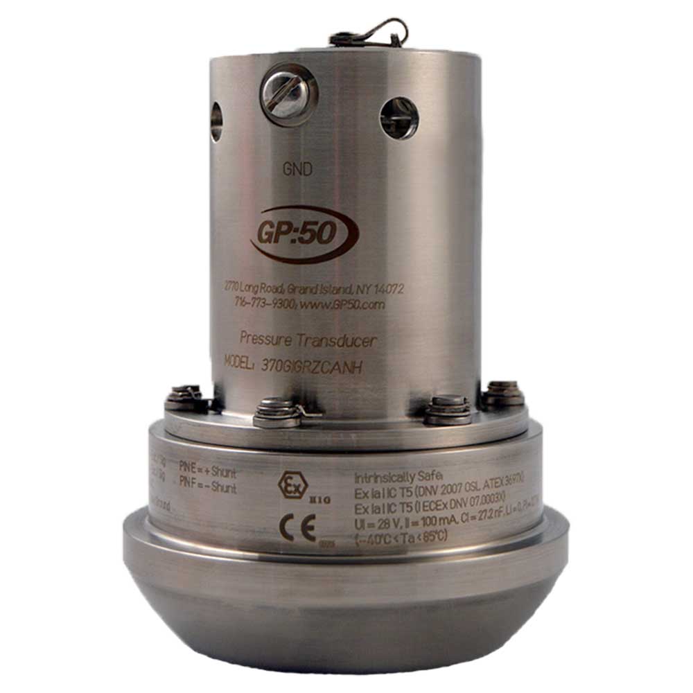
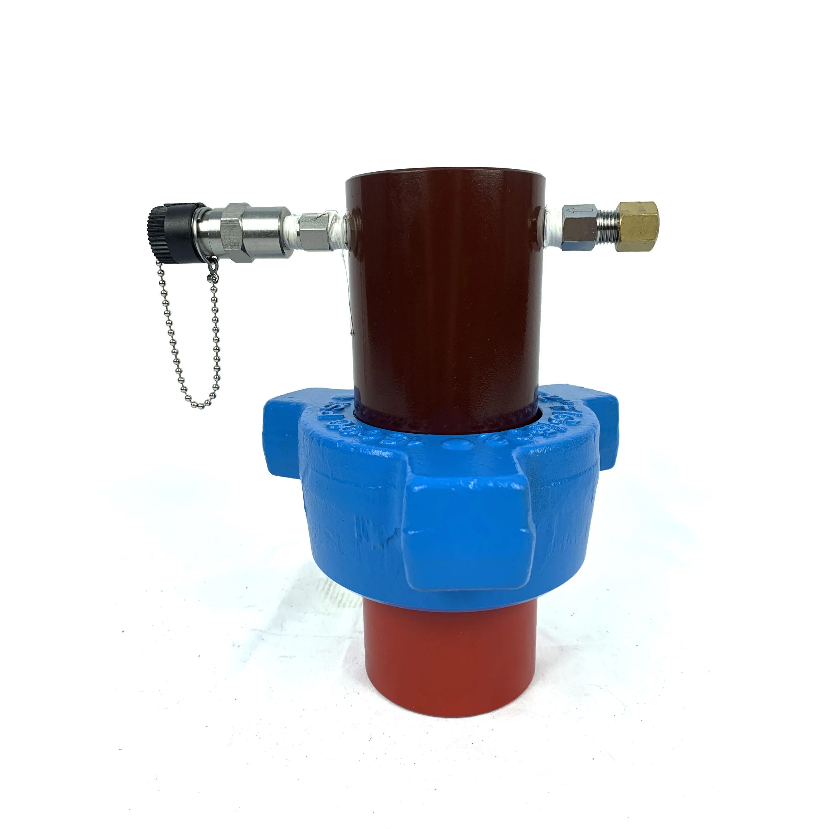
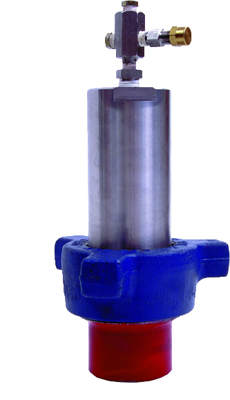
Honeywell offers a variety of pressure sensors used in oil and gas drilling and exploration. Our Wing Union pressure sensors are exclusively designed for oil and gas use. These all-welded, hermetically-sealed, stainless steel pressure sensors with X750 Inconel® design are used with 1502 and 2202 WECO® fittings and are built to withstand the rigors of mud pumping, cementing, well stimulation and coiled tubing applications. Honeywell also offers other specialty pressure sensors for use in drilling measurements, monitoring of pressurized tools, mud pulsation, well logging and more. Intrinsically safe and explosion-proof versions are also available for use in hazardous locations. For a comprehensive list of oil and gas specialty sensors, please refer to our models below. Custom engineering is a Honeywell specialty. If you don’t see exactly what you need, contact us to discuss your unique needs. Features Specialty built, rugged sensors for tough offshore and land oil and gas exploration and drilling applications Stainless steel and X750 Inconel construction, hermetically sealed for use in liquid or wet environments Wing Unions offer 0.2% accuracy and ranges up to 20,000 psig Other intrinsically safe / explosion proof pressure sensors to operate in hazardous locations or where enhanced safety is required Products available with CSA, ATEX, DNV, UL, IECEx and CE certifications as required
Product&Reapir: Crown block(TC225 TC250 TC315 TC450 TC585), Travelling block(YC225 YC250 YC315 YC350 YC450 YC450S YC585), Hook(DG225 DG250 DG315 DG350 DG450 DG585 DG675), Rotary table(ZP175 ZP205 ZP275 ZP375 ZP975AS ZP495), Swivel(SL225 SL250 SL450 SL585), Drawworks(JC20 JC30 JC40 JC50 JC70B JC90DB), Mud pump (F-500 F-800 F-1000 F-1300 F-1600 F-1600HL F-2200 F-2200HL 3NB500C,3NB1000C 3NB1300C 3NB1600 SL3NB-1000 SL3NB-1300A SL3NB-1600A),BOP(FH,FZ,Cameron,Shaffer), Control System for Surface Mounted BOP Stacks(FKQ,FKDQ),Disc brake (PS,PSZ, DBS), Bladder accumulator (NXQ), Drilling rig(ZJ40/2250DZ ZJ50/3150DZ ZJ70/4500DZ ZJ90/6750DZ), Workover rig (XJ40,XJ60, XJ80,XJ100,XJ12,ZJ15,ZJ20,ZJ3,XJ350, XJ450, XJ550,XJ650,XJ750), BPM Top drive((DQ120BSC, DQ90BSD, DQ90BSC, DQ80BSC, DQ70BSD, DQ70BSE, DQ70BSC, DQ50BC, DQ40BC, DQ40BSG, DQ40BCQ, DQ40YR, DQ30Y) Make: Bomco, Lanzhou LS,LSPE, SJ Petro, RG Petro, Sichuan Honghua, CPTDC, Beijing BPM, Shanghai Shenkai, Kingdream, CCDC, SJS Serva, DFXK, LS-NOV, Beijing PSK, Gold basin, Renqiu Boke,Guangdong Dongsu.(Guangshi), XBSY.,Tiehu, Rongsheng (HBRS), TSC. Replacements:Mission magnum/Halco centrifugal pump, Cameron FC gate valve,Cameron R check valve, Demco mud valveE( 3K&5K ), Demco butterfly valve,BJ varco handling tools (SDXL, SDML, SDS,DCS,SSC,SSD,YT, HYC, LYT, MP,MYT, MG, RGG, HGG, MGG, TA, SJ), MI SWACO / Mongoose / Derrick / /Brandt / King cobra shale shaker screen (FLC2000,FLC503,Derrick 626), M/D & OTECO Gauge(Type F,Type D,Model 6,Model 7,Model 8), Twin disc,WPT, Eaton clutch & friction disc, National (10-P-130,12-P-160 ,14-P-220 ,8-P-80 ,9-P-100), Gardner denver (PZ-7,PZ-8,PZ-9,PZ-10,PZ-11), EMSCO FB1600.International Brand: Moog, CCS, ATOS, Rexroth, Eaton, Flowrox, Italvibras, Martin, Norgren, Parker, Siemens, Vickers, 3M.Standard:API Spec 4F, API Spec 6A,API Spec 6D,API Spec 600, API Spec 7K, API Spec 8A, API Spec 8C,API Spec 16A, API Spec 16C, API Spec 16D

Hammer union pressure transmitters, also called wing union pressure transmitters, are pressure sensors designed specifically for use in the extremely harsh conditions found in on-shore and off-shore oil and gas rigs. They are ideal for measuring the high pressures associated with drilling, fracturing, mud logging, cementing, acidizing, mud pumps and wellhead monitoring.
Designed to fit inside the hammer or wing unions commonly used in the oil and gas industry to make tight connections between sections of pipe, hammer union pressure transmitters are engineered to withstand the vibration, shock, high pressures, rough handling, and highly abrasive & corrosive media typical of the oil and gas industries.
Generally available in pressure ranges from 5,000 to 20,000 psi, hammer union pressure transmitters are built to comply with international standards for hazardous environments.
The Chicago Pneumatic 2200702805 pressure rransducer is an OEM part by CP. This may be shown in your parts manual as 2200 7028 05, 2200-7028-05 or 2200702805. . This item was used on a number of their QRS and CPVS rotary screw air compressors manufactured after 2010. The pressure transducer senses the outgoing air pressure and sends a signal back to the compressor to build air, unload, or shut down. The pressure transducer will often need to be replaced if a false pressure signal is being sent into the compressor to turn on or off at incorrect times.
CROSS-REFERENCE TO RELATED APPLICATIONS This application claims priority to Provisional U.S. Application Ser. No. 61/679,748, titled "Differential Pressure (DP/DT) Mud Pulse Telemetry While Pumping" and filed August 05, 2012 by Victor J. Stolpman, which is hereby incorporated herein by reference.
In most drilling operations, a circulation pump circulates fluid through a drill string and out the drill bit into a borehole. This fluid (often called "mud" in the oilfield industry) may include water and/or oil and additional additives that may be inert or chemically reactive with other molecular compositions present within a borehole during drilling operations. There are a multitude of motivations for pumping mud with one example being simply to remove earth materials from the borehole.
In Mud Pulse Telemetry (MPT), a measurement-while-drilling (MWD) service company (e.g. Halliburton"s Sperry Drilling) may install at least one transducer/sensor within the surface rig"s plumbing system. The surface rig"s plumbing system mechanically connects the circulation pump(s) (also known as "mud pumps") with the drill string, which in turns couples with a drill-bit within the borehole. MPT systems employ downhole "pulser" located near the drill bit to transmit a series of modulated pressure waves through the mud column within a drill string to communicate real-time information to the surface transducers/sensors. However, the surface transducers may be unable to acquire the encoded pulse waveforms due to various forms of attenuation and interference. For example, the circulation pump hinders the operation of the MPT system through the introduction of pump noise. One attempted solution employs pump dampeners (sometimes called "de-surgers") to buffer the fluid itself,
Accordingly, there are disclosed in the drawings and detailed description specific embodiments of methods and systems that provide effective pump noise removal, thereby enabling differential pressure mud pulse telemetry while drilling. In the drawings:
The following description relates to a variety of mud pulse telemetry (MPT) method, apparatus and system embodiments that enable Measurement While Drilling (MWD) services with real-time data transfer from sensors in a bottomhole assembly (BHA) to a surface location. This disclosure does focus on the receiver side configurations, but this does not imply that this disclosure is limited to surface systems. One skilled in the art will recognize that non-surface system embodiments are readily derivable from the ensuing description.
Fig. 1 depicts an illustrative Mud Pulse Telemetry (MPT) apparatus embodiment and system embodiment in use at a typical drilling installation while operating a Measurement While Drilling (MWD) service. As illustrated, the typical drilling installation includes a drilling derrick 102 at the surface of the well. The derrick may be transportable and temporarily erected on location. The drilling derrick 102 supports the drill string 104 and BHA 106 via a hoist 108 and swivel 110. In the Fig.1 example, the BHA 106 includes a pulser 112, a tool sensor 114, and a drill bit 116. The BHA may further include additional MWD tools, stabilizers, and/or drill collars or heavyweight drill pipe (HWDP) to stiffen the BHA and add additional weight to aid with keeping the drill bit "on-bottom".
The hoist 108 lowers drill string 104 through the rotary table 118 into the casing 120 and beyond into the open borehole 122 until the bit 116 reaches the bottom. The rotary table 118 turns the drill string 104 and bit 116 to extend the borehole through earth formations. If desired, a downhole mud motor can be employed to rotate the bit at a different rate than the drill string.
Circulation pumps 124 take drilling fluid ("mud") from a retention pit 125 and circulate it through a feed pipe 126 to swivel 110 where it flows downward through the drill string interior as indicated by arrow 128. Once the fluid reaches the bit 116, it exits through ports near the cutting elements to entrain and transport rock cuttings upward along the
annulus as indicated by arrow 130. The fluid transports the cuttings into the retention pit 125 via return pipe 132. As the drilling mud circulates through the drill bit, the drilling fluids function additionally as a bit coolant and lubrication extending the lifespan of the bit. Ideally, the weight and hydraulic pressure of the drilling fluid flow balances with the formation pressure to minimize fluid loss to the formation while still preventing an uncontrolled release of formation gases and fluids into the borehole, i.e. a "blowout."
Pumps 124 are normally piston-based, causing a significant degree of pressure variation due to the action of the pistons and valves. A pulsation dampener 134 is positioned along the feed pipe 126 to attenuate the (relatively) high-frequency variation, typically with only a moderate degree of success. Downstream of the pulsation dampener, Fig. 1 shows multiple transducers 136 that respond to pressure variation of fluid in the feed pipe 126. The transducers 136 can be directly coupled to the fluid to physically respond to pressure variations, or coupled to a tubular housing the fluid flow to measure dimensional changes resulting from pressure variation in the flow stream. The transducer provides a measurable reference signal (e.g. voltage, current, phase, position, etc.) sensitive to the temporal derivative of pressure, i.e. dP(t)/dt, with a response that is proportional to within an understood distortion (e.g., scalar gain, constant phase shift, time-shift, finite precision, etc.).
A transducer interface 138 converts the transducer response into an electrical signal suitable for digitization and processing by system 140. System 140 may be dedicated MPT receiver electronics or a general purpose computer with a data acquisition card and suitable software for processing the acquired transducer signal(s). Among other things, system 140 may include circuitry, firmware, or software that implements a pump noise filter that produces a receive signal having a reduced pump noise component.
To communicate with the surface, a downhole "pulser" induces pressure fluctuations in the flow stream 128. The pressure fluctuations propagate upstream as pressure waves 142
until they reach the transducers 136. Information can be encoded into the pressure waves via modulation such as frequency modulation, phase modulation, pulse position modulation, and pulse width modulation. Other suitable modulation schemes also exist. The chosen modulation scheme preferably provides sufficient detection signal-to-noise ratio despite the attenuation, dispersion, and noise effects introduced into the flow stream 128.
As part of the BHA 106, the down-hole pulser 112 may be mechanically and/or electrically coupled with additional down-hole sensors 114 that measure, calculate and/or sense various conditions within or near the bottom of the borehole being drilled. The BHA may have an electrical power source and inter-communicating control buses that facilitate the transfer of data between BHA components. Not limited to the following, the electrical power source may be batteries and/or generator-based deriving power from the flow of fluids via turbine or like mechanism. Likewise, not limited to the following, said control bus lines may be of a metallic, conductive material for use with electrical systems and/or dielectric material when used with optical sources. Fig.1 illustrates a single downhole tool sensor coupled with a pulser, but those skilled in the art understand MWD BHA configurations may have a multitude of tools above and/or below a pulser and may utilize more than one communication media, e.g. mud pulse and electromagnetic telemetry.
A downhole controller may be included in the BHA with electronic circuitry that collects from the various sensors measured formation evaluation values such as density of rock formation, pressure of the drilling fluid, and gamma ray readings, and resistivity of rock formation. Additional measurements may include directional information such as but not limited to inclination, tool-face, azimuthal, and/or surveys. The controller may include an encoding module (e.g., in the form of circuitry or a programmable processor executing software in an associated memory device) that encodes the collected information as a data stream for transmission by the pulser 112.
The pulser 112 actuates a valve at least in part to encoding the measurement data stream as pressure modulations of the flow stream. Fig. 2A shows a first illustrative pulser implementation having a valve or variable flow restrictor formed from a circular, fan-like stator 201 having multiple fan blades/fins extending radially from a central hub, and a similarly shaped rotor 202 that can oscillate with respect to the (stationary) stator 201. In this implementation, the valve is said to be closed when the relative alignment of the stator and rotor fins maximally restricts fluid flow (by misaligning the openings between blades). It is said to be open when the relative alignment of the stator and rotor fins minimally restricts fluid flow (by aligning the openings between blades).
The valve is coupled serially within the fluid column to restrict (when closed) or ease (when open) the flow of fluid through the valve towards the drill-bit. When the valve is closed, a pressure build up occurs within the fluid on the source side creating a positive pressure change that propagates up to the surface. A subsequent opening of the valve enables the upstream pressure to drop to its previous pressure. Thus as the rotor 202 oscillates, the valve creates a periodic pressure pulsation that is amenable to frequency and phase modulation.
Fig. 2B shows a second illustrative pulser implementation having a spinning rotor 204 in place of an oscillating rotor 202. As before, the alternation between alignment and misalignment of the openings between the blades produces a periodic pressure pulsation that can be frequency and phase modulated. A spinning rotor may offer better frequency stability at the expense of a more limited modulation range.
Fig. 2C shows a third illustrative pulser implementation having a flow orifice 206 and a poppet 208 that moves relative to the orifice to restrict (when closed) and ease (when opened) the flow of fluid through the valve. A closing and re-opening of the valve (also referred to as a momentary closing of the valve) generates an upgoing pressure pulse
Fig. 2D shows a fourth illustrative pulser implementation, which is often termed a "negative pulser". This pulser configuration includes a bypass valve to vent fluid from the drill string bore into the annulus, thereby bypassing the drill bit. This venting of drilling fluid produces a pressure drop (i.e. a negative pressure change) within the drill string"s fluid column. Fig. 2D shows a valve seat and gate 210 configuration. The gate 210 moves relative to the seat to close the valve (i.e., restrict fluid flow into the annulus) and open the valve (permit fluid flow into the annulus). After closing the valve, the fluid pressure immediately rises in the drill-string column towards the steady- state pressure prior to the valve"s opening of the valve. As the name suggests, this opening and closing actuation of the valve creates a negative pulse that propagates throughout the column of drilling fluid.
In the configurations of Figs. 2C and 2D, the valve is controllable to generate individual pressure pulses that propagate to the surface, enabling the use of pulse width modulation and pulse position modulation. The modulation (whether frequency, phase, pulse position, pulse width, or some other form of modulation) is handled by the receiver after the pressure variation signals have been acquired via the transducer(s) 136.
Conventional strain gauge sensors may serve as transducers 136 to provide a measurable reference, e.g. 4-20mA current, proportional to the mechanical fluid pressure present at the coupling point, i.e. P(t), by being directly coupled to the drilling fluid flow. Alternatively, such strain gauges could be employed to measure the strains that the rig"s plumbing undergoes when a mud pulse is present and/or absent. Examples of manufacturers of said sensors include but not limited to Honeywell and Rosemount (Emerson Electric affiliated).
Alternatively, as shown in Fig. 1, transducers 136 may respond to the temporal derivative of the pressure signal at each coupling point, i.e., dP(t)/dt, or the derivative of a
commensurate strain in the plumbing that is proportional to the pressure signal derivative. For the former measurement, direct coupling of the transducer to the fluid flow can be used. For the latter, the transducer can be coupled to the surface of a tubular in the drill rig"s plumbing (e.g., feed pipe 126). In the illustrated embodiment, transducers 136 each include an optical fiber winding on the feed pipe to measure the strains via small changes in the feed pipe dimensions.
Despite the presence of pulsation dampener 134, the measurements of transducers 136 include a significant pump noise component. Accordingly, system 140 includes a pump filter that targets the cyclostationary noise generated by the pump strokes. Fig. 3 A shows an illustrative pressure variation P(t) that might be present within a feed pipe fluid flow carrying a mud pulse telemetry signal. Fig. 3B shows an illustrative pump noise component of this pressure variation. Notably, this pump noise component is the primary source of pressure variation, but it has a regular cyclostationary character that enables accurate estimation. Fig. 3C shows the difference between the illustrative pressure variation and the illustrative pump noise component. The pressure variation in this illustrative difference is primarily the mud pulse telemetry signal.
Various embodiments of a pump filter may utilize memory storage for holding estimates of "pump signatures". A pump signature estimator may extract such pump signatures from transducer measurements (including transducers responsive to the temporal derivative of pressure, dP(t)/dt ) of the drilling fluid flowing through the tubular at each location where the transducers are coupled with the rig"s plumbing. A pump stroke position monitor (e.g., a whisker switch whose state is coupled to the pump piston"s position) may be included in system 140 and used by the pump signature estimator and the pump filter module to assist with noise removal. The pump signature expectedly includes acoustic distortions of pump noise observable at the transducer locations, including channel effects such as
attenuation, dispersion, and acoustic reflections. In some embodiments, the pump filter module obtains a negated pump signature from the estimator and adds it to the receive signal. The pump signature can be stored in derivative form or regular pressure domain form. The system 140 may employ a processor to identify pump filter parameters and maintain said pump signatures. The system 140 then relies on the pump signatures to filter and remove at least a portion of the cyclostationary pump noise, thereby yielding at the pump filter"s output a filtered version of the transducer measurements.
Fig. 4 shows illustrative signals with an expanded time axis. Curve 402 is an illustrative pressure derivative dP(t)/dt signal which, when integrated over time, yields a pressure P(t) curve 404. For comparison, curve 406 is a pressure curve acquired with a strain gauge sensor. However, this disclosure contemplates measurements of any physical phenomenon that reflects the pressure fluctuations of the surface fluid flow.
Fig. 5 shows an illustrative MPT receiver having an analog integrator. Transducer interface 138 is implemented as an interferometer having a light source 502 which transmits at least one spectral frequency or wavelength to a optical splitter 504. Illustrative light source 502 types include a laser diode, a laser, and a light emitting diode. The optical splitter 504 sends light 506 and 508 in opposite directions around a loop formed from a series of optical waveguides. The illustrated loop includes a fiber optic cable 510, a reference (delay) coil, and a transducer 136 coupled to the feed pipe 126. Additional transducers 136 can be employed for redundancy and/or enhanced signal processing (including directional detection). For example, the embodiment of Fig. 1, has three transducers 136 to obtain spaced apart dP(t)/dt measurements. The transducer locations need not be limited to the feed pipe 126, but rather they can be positioned at any suitable location in the rig"s plumbing including the stand pipe, flex hose, return line, or the casing annulus.
possibly mechanically attached or adhered) around the drilling rig"s plumbing with sufficient contact such that changes in the tubular housing due to fluid pressure will change the tension within the fiber optic dielectric. The loop returns the light 514 and 518 to optical splitter 504, which provides a combined beam to light sensor 520. The overall fiber optic loop has a finite path length, say L, and includes a measurement section (i.e. portion of cable wrapped against the conduit housing) of a length less than L, say X where X< L, and delay section also of finite length, say L-X. In one embodiment, the measurement section may be 2-10 meters in length. In this example, the measurement portion is at least partially wrapped against said conduit containing pressurized fluids and encoded pulses. In some embodiments, the delay section is on the order of 500-3000 meters in length.
Given a constant pressure condition P(ti) within said conduit, the two light beams transverse the same L distance to recombine with a first relative phase φ(ίι) (i.e. a physical measurable phenomenon) at the detector. (Note that the relative phase need not be zero if the optical paths are not identical, for example, perpendicularly polarized beams may have slightly different propagation velocities. Alternatively, unidirectional couplers can be employed to create a slight path difference for the counter-propagating beams.)
Now assume a second pressure condition with a pressure change ΔΡ(ί2) = P(t2) - P(ti), where At = t2 - 1\ = (L-X) n / c is the time delay provided by the delay coil 512 where c is the speed of light, and n is the refractive index of the optical fiber. This time difference is also the time between the counter-propagating beams" arrivals at the measurement section. The difference in pressure at the two times introduces a change in the path length encountered by the two beams, yielding a relative phase φ(ί2) with a difference Δφ = φ(ί2) - φ(ίι) that is proportional to the change in path length. Thus return light beams 514 and 518 experience travel time differences due to the changes in pressure.
When the return light undergoes interference between the counter-propagating beams in this Sagnac configuration, the resulting light intensity represents a time derivative of the path length, which in the frequency range of interest, is entirely attributable to the pressure- induced dimensional changes of the feed pipe 126. The light sensor 520 may provide a current, voltage, or other electrical signal attribute representing amplitude, phase, intensity, and/or a non-linear signal dependence on the transducer measurand. In the illustrated embodiment, the sensor produces a voltage that is proportional to a time derivative of the fluid pressure at the location of the transducer 136. A gain control amplifier 522 scales the signal into a desired signal range and may provide compensation for non- linear effects. Integrator 524 performs an analog integration operation to provide an accumulated differential pressure measurement, e.g., using an integrating operational amplifier or some other form of analog filter.
In the embodiment of Fig. 5, system 140 includes an analog-to-digital converter 526 to digitize the signal from the transducer interface 138. System 140 further includes an processing module 528 for initial filtering of the digital signal stream, e.g., low pass filtering, decimation to a desired sampling rate, etc. A pump filter module 530 removes pump noise from the signal. Modules 532 and 534 perform demodulation and decoding to extract the telemetry data stream from the filtered signal. In at least some system embodiments, these modules can be combined to enable so-called "soft" decoding. A data module 536 performs de-framing and demultiplexing to separate the data stream into log data for the corresponding sensors. Log module 538 performs tool-specific processing of the log data to derive the tool logs as a function of tool position. A display module 540 presents the tool logs as a printed or displayed image or in some other non-transient, tangible form such as database system that stores data and makes it available as needed in formatted reports and log plots. System 140 may include a graphical user interface (GUI) or may be coupled to a computer or computer
For example, Fig. 6 shows an alternative MPT receiver having a digital integrator 550 rather than the analog integrator 524 of Fig. 5. In Fig. 6, the digital integrator 550 is positioned between the pump filter 530 and detector module 532, but it could equally well be positioned before the pump filter 530 or even before the processor module 528. Alternatively, digital integrator 550 could be combined with one of these other modules. In the illustrated configuration, pump filter 530 is able to operate solely with pump signatures in the derivative domain (dP/dt) rather than in the pressure domain P(t). There may be certain competitive advantages created by the use of a pump filter with at least one surface dP/dt sensor, and certainly by the use of transducers that do not require direct access to the fluid flow or cutting of the rig plumbing. Such non-invasive transducers further facilitate the placement of multiple transducers to enable array filtering and signal-to-noise ratio improvement through the use of multiple independent sensors having spatial diversity.
Some alternative embodiments may further include at least one additional pump filter for removing residual pump noise. In some cases, the additional pump noise filter operates on the derivative signal dP/dt, whereas in others the additional pump noise filtering occurs after an integration of dP/dt signals.
measurements from one or more downhole sensors 114, and through the use of dedicated circuitry 704 or a programmable processor 706 coupled to memory 708 to execute suitable encoding software, converts the measurements to a modulated data stream 710. A pulser 112 transmits the modulated data stream as a series of pressure variations 142 to the surface. With one or more transducers, the pressure variations 142 are converted by transducer interface(s) 138 to derivative pressure signals dP/dt. An analog integrator 524 integrates the derivative signal to provide processor module 528 with a pressure signal P(t). A pump filter module 530 removes at least some of the pump noise, and decoder module 534 converts the signal into a received data stream. Data module 536 demultiplexes the data stream into log data for the individual sensors, and logging module 538 performs tool-specific processing of the log data. A user interface 720 controls the demultiplexing process and enables viewing and processing of the log data.
Fig. 8 is distinguished from Fig. 7 by the omission of analog integrator 524 and the insertion of digital integrator 550 after the pump filter 530. As before, this placement of the digital integrator enables pump noise filtering to be performed on the pressure derivative signal.
In terms of method embodiments, at least some of the disclosed MPT systems sense pressure, strain, and/or some other physical phenomenon indicative of the time derivative of pressure fluctuation in a drilling fluid flow to within an understood distortion. The sensing may occur at one or more points in the drilling rig"s surface plumbing, such as a feed pipe downstream of a pulsation dampener. The sensed derivative is processed to remove at least some of a pump noise component before being demodulated and decoded to extract the telemetry data stream. At least some of the disclosed system embodiments include analog or digital integration to convert the derivative signal into a pressure signal. As part of the demodulation and decoding process, some system embodiments may include equalizers,
pulse detectors, edge detectors, and/or timing modules to decode the receive signal. Some system configurations may employ array processing of the signals as part of the pump noise removal and/or the equalization process. As part of the pump noise removal, some system embodiments estimate the pressure derivative pump signatures with a training or adaptive filtering process, store the signatures in memory, and subtract the signatures from the corresponding transducer signal. The signature estimation and removal operations may include a phase lock loop to track a fundamental frequency or period of the pump noise and a current phase. At least some disclosed embodiments may additionally or alternatively sense a pump stroke position with a sensor affixed to the pump.
At least some of the disclosed MPT system embodiments perform pump noise filtering in stages, with a first pump noise filter removing some of the pump noise prior to integration, and a second pump noise filter removing residual pump noise after integration. Each pump noise filter may include modules for estimating a pump noise signature at that stage of processing.
While certain signals are described herein as being proportional to pressure, a time derivative, or some other physical property, those of ordinary skill in the art will recognize that this proportionality may only be true to within an understood distortion, e.g. quantization, A/D range, mean-squared-error, additive thermal noise, constant offset, known calibration function, etc.).
Numerous modifications, equivalents, and alternatives will become apparent to those skilled in the art once the above disclosure is fully appreciated. For example, the foregoing description focuses on uplink communication from the BHA to the surface, but this disclosure also applies to downlink communication from the surface to the BHA, with the noise filters being employed to remove cyclostationary noise from downhole noise sources such as the bit, mud motor, rotary steerable device, and/or friction between the BHA and the


 8613371530291