
mud pump pressure transducer free sample
The field adjustable Model 470 WECO® Hammer Union Pressure Transmitter from GP:50 is ruggedly designed and engineered to effectively address demanding shock and vibration and installation challenges within the oilfield environment. Units are directly compatible with WECO® 2”-1502, 2202, 2002 or 602 wing union fittings. The field adjustment option provides for zero and span adjustments as well as rangeability. This field adjustable option eliminates the need to rescale your panel meter when replacing transmitters and allows for fewer pressure ranges to stock. Learn More
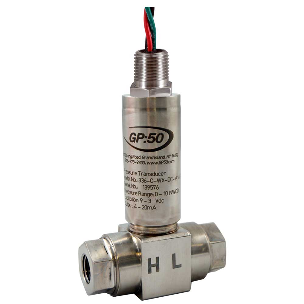
The Model 136/236/336-AI/AF from GP:50 is a family of highly accurate, digitally compensated differential pressure transducers. Model 136/236/336-AI/AF measures differential pressure ranges as low as 20” WCD and line pressures up to 1000 PSID (69 BAR) in a compact size. Customers may also choose from among multiple accuracy, digital output, process and electrical connections. Please consult the factory for details. Learn More
The Model 136/236/336-AI/AF from GP:50 is a family of highly accurate, digitally compensated differential pressure transducers. Model 136/236/336-AI/AF measures differential pressure ranges as low as 20” WCD and line pressures up to 1000 PSID (69 BAR) in a compact size. Customers may also choose from among multiple accuracy, digital output, process and electrical connections. Please consult the factory for details. Learn More
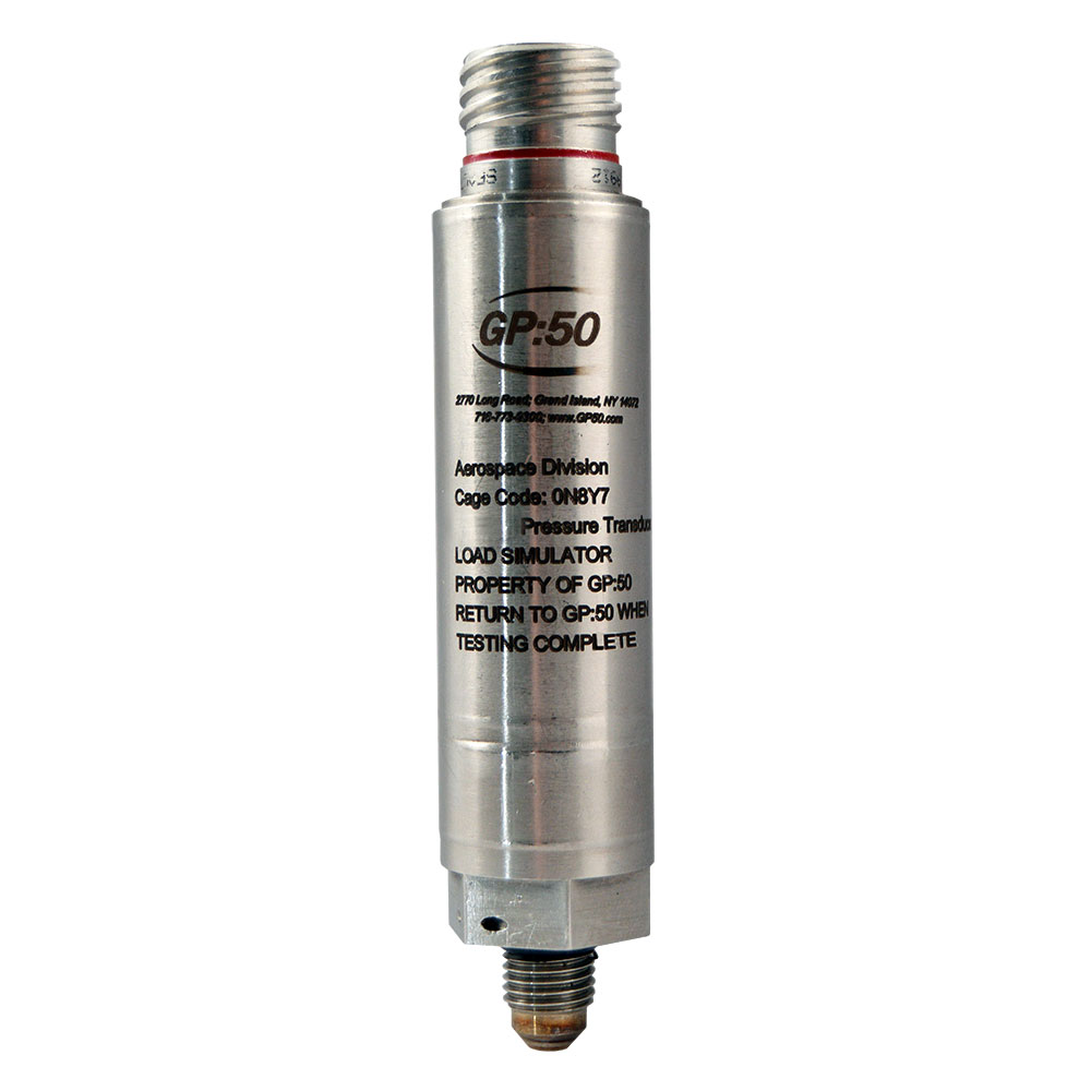
Model 7100 flight-heritage, low level pressure transducer from GP:50 is designed to provide high-accuracy measurements of up to ±0.1% FSO. Its flight heritage, spanning 25 years, makes it ideal for use within demanding aerospace and defense applications, including those in which higher shock and vibration levels may be present. Its compact and lightweight design facilitates ease of installation within space constrained environments. Learn More
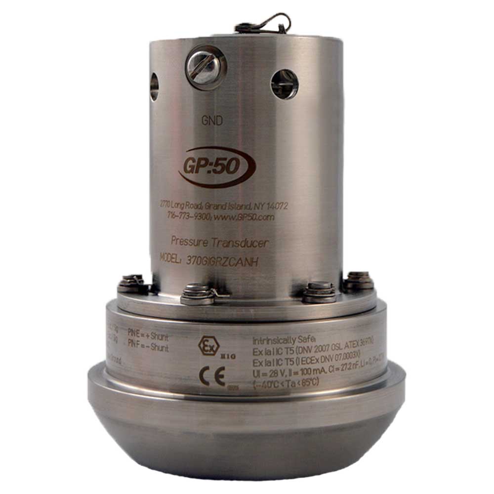
The industry exclusive Model 170/270/370 WECO® Hammer Union Pressure Transmitter from GP:50 is ruggedly designed and engineered to effectively address demanding shock and vibration and installation challenges within the oilfield environment. Units are directly compatible with WECO® 2”-1502, 2202, 2002 or 602 wing union fittings. They are also available in multiple outputs, ranges, electrical connections, and area approvals to meet specific requirements. Buy OnlineLearn More
The Model 8200 series from GP:50 is a flight heritage, high level pressure transducer. Digitally corrected to provide high-accuracy pressure measurements with a proprietary sensor design for added zero stability for commercial aviation, military, aerospace, UAV, satellite, and defense
automation, test stand, and OEM applications. Its rugged stainless steel design offers high corrosion resistance in pressure ranges from 0-25” WC (69 Mbar) to 30K PSI (2068 bar). Learn More
Model 241/341 from GP:50 is our most accurate pressure transducer. Designed specifically for aerospace and automotive test stand applications, it is 5x tighter through temperature than standard industrial transmitters with a 0.20% FSO / 100 °F thermal stability. More than 25 years of field expertise went into the design of our pressure transducer for exceptional reliability. The compact, corrosion-resistant, all-welded stainless steel design of the Model 241/341 offers ease of installation within space constrained environments. Static accuracy is available to ±0.05% FSO, with a total thermal error of 0.25% FSO over the compensated temperature range. Learn More
Model 241/341 from GP:50 is our most accurate pressure transducer. Designed specifically for aerospace and automotive test stand applications, it is 5x tighter through temperature than standard industrial transmitters with a 0.20% FSO / 100 °F thermal stability. More than 25 years of field expertise went into the design of our pressure transducer for exceptional reliability. The compact, corrosion-resistant, all-welded stainless steel design of the Model 241/341 offers ease of installation within space constrained environments. Static accuracy is available to ±0.05% FSO, with a total thermal error of 0.25% FSO over the compensated temperature range. Learn More
The Model 136/236/336 from GP:50 is a family of highly accurate, digitally compensated differential pressure transducers. Model 136/236/336 measures differential pressure ranges as low as 20” WCD and line pressures up to 1000 PSID (69 BAR) in a compact size. Customers may also choose from among multiple accuracy, digital output, process and electrical connections. Please consult the factory for details. Learn More
Model 536 CAN Bus from GP:50 is a compact, high-accuracy, digital output differential pressure transducer. This Model measures differential pressure ranges as low as 0-20” WCD (50 mbar) and line pressures up to 1000 PSID (69 BAR) in a compact size with improved thermal performance to meet the demands of the automotive, medical and laboratory test markets. The CAN Open protocol allows for multiple devices on a single bus, reducing installation time and cost. Learn More
Model 536 CAN bus from GP:50 is a compact, high-accuracy, digital output differential pressure transducer. This Model measures differential pressure ranges as low as 0-20” WCD (50 mbar) and line pressures up to 1000 PSID (69 BAR) in a compact size with improved thermal performance to meet the demands of the automotive, medical and laboratory test markets. The CAN open protocol allows for multiple devices on a single bus, reducing installation time and cost. Learn More
The Model 1002/1003 OEM Industrial Grade Pressure Transmitter from GP:50 is a family of lower cost, industrial grade OEM pressure transducers, featuring corrosion-resistant, all stainless steel wetted parts and housings. Series transducers are ideal for higher volume pressure monitoring applications, particularly where lower costs are required, yet where the need for precision measurement accuracy remains. Units are available with choice of 4-20 mA, 0 to 5 Vdc or 0 to 10 Vdc output, as well as various electrical connection and pressure port options. Typical
costs are required, yet where the need for precision measurement accuracy remains. Units are available with choice of 4-20 mA, 0 to 5 Vdc or 0 to 10 Vdc output, as well as various electrical connection and pressure port options. Typical applications for the Model 1002/1003-CA include off-road vehicle, HVAC/R, hydraulic and pneumatic control systems, pumps and compressors, and industrial engine pressure monitoring. Learn More
The Model 111/211/311 from GP:50 is a family of industrial grade pressure transducers. These strain gauge-based sensors are expressly designed to withstand the shock, vibration and pressure spikes common to most hydraulic and pneumatic control systems.
The highly rugged, all-welded stainless steel design of the Model 111/211/311 offers high corrosion resistance, making the sensors an ideal choice for demanding oil & gas, steelworks, rolling mills and process control applications. Units are further available with optional 10X proof pressure for extended worry-free service life within challenging environments. Learn More
The Model 216/316 from GP:50 is a family of low range, high line, differential pressure transducers. Their compact design incorporates GP:50’s own digital correction circuit technology, for high accuracy and extended service life across a variety of applications.
GP:50 model 540 CAN Bus digital output pressure transducer provides high resolution, accuracy, and improved thermal performance to meet the demands of the automotive, medical and laboratory test markets. The CAN Open protocol allows for multiple devices on a single bus reducing installation time and cost. Learn More
The Model 541 series is our most accurate CAN based pressure transducer. Designed specifically for test stand applications, the CAN Bus protocol provides high resolution, reduced noise and improved thermal performance. The compact, all-welded stainless steel design of the Model 541 offers ease of installation within space constrained environments. Static accuracy is available to ±0.05% FSO, with a total thermal error of 0.25% FSO over the compensated temperature range. Learn More
The Model 541 series is our most accurate CAN based pressure transducer. Designed specifically for test stand applications, the CAN Bus protocol provides high resolution, reduced noise and improved thermal performance. The compact, all-welded stainless steel design of the Model 541 offers ease of installation within space constrained environments. Static accuracy is available to ±0.05% FSO, with a total thermal error of 0.25% FSO over the compensated temperature range. Learn More
Model 188/288/388 from GP:50 is a family of all welded stainless steel miniature flush diaphragm pressure transducers. Their unique design incorporates a specialty flush process connection. This allows the transducer to effectively support higher viscosity fluid pressure measurements without port clogging or plugging. Their compact size allows for ease of installation within space constrained environments. Learn More
Model 188/288/388 from GP:50 is a family of all welded stainless steel miniature flush diaphragm pressure transducers. Their unique design incorporates a specialty flush process connection. This allows the transducer to effectively support higher viscosity fluid pressure measurements without port clogging or plugging. Their compact size allows for ease of installation within space constrained environments. Learn More
The Model 340T temperature transducer is essential where reliable and accurate process temperatures are required. With a large range of temperature ranges and probe lengths available, the Model 340T is adaptable for most temperature applications or processes. The compact size provides easy installation for on-board vehicles used in the oil and gas industry. Learn More
The Model 243AI/AN / 343AI/AN Series from GP:50 is an all-stainless steel, dual pressure and temperature transducer with 4-20 mA and 0-5 V output. Its compact design reduces I/O and insertion points where size and weight are considerations. Units are available in a variety of pressure and temperature ranges. Learn More
The Spike Series from GP:50 is a family of pressure transducers, specifically designed to withstand high-amplitude, high-frequency spikes that commonly occur in hydraulic pressure sensing applications. A proprietary sensor design provides increased over pressure protection as high as 10x. Learn More
Models 280/380 & 283/383 from GP:50 are a family of food and beverage grade tri-clamp process connection pressure transmitters. Their rugged design also meets 3A sanitary standards for dairy applications. Tri-clamp fitting sizes as small as 3/4” are available to provide reduced surface area exposure. The Model 383 is also available with optional high-temperature
Models 280/380 & 283/383 from GP:50 are a family of food and beverage grade tri-clamp process connection pressure transmitters. Their rugged design also meets 3A sanitary standards for dairy applications. Tri-clamp fitting sizes as small as 3/4” are available to provide reduced surface area exposure. The Model 383 is also available with optional high-temperature
The Model 250/350 AI/AN from GP:50 is a flow-thru pressure transmitter with a unique one-piece design. This flow-thru design provides a zero internal dead volume eliminating the need for piping tees or dead ended process connections. This design removes the possibility of trapped media or contamination and allows for a Clean In Place (CIP) device, providing for a sanitary, in-line solution for the pharmaceutical market especially rated for high pressure homogenization systems. Learn More
The Model 250/350 AI/AN from GP:50 is a flow-thru pressure transmitter with a unique one-piece design. This flow-thru design provides a zero internal dead volume eliminating the need for piping tees or dead ended process connections. This design removes the possibility of trapped media or contamination and allows for a Clean In Place (CIP) device, providing for a sanitary, in-line solution for the pharmaceutical market especially rated for high pressure homogenization systems. Learn More
The Model 311-IM from GP:50 is a flush mounted, hazardous location approved pressure transducer, designed to provide added reliability within slurry or thick process media applications. Their rugged, all-welded flush mounted design facilitates accurate measurements of corrosive or higher viscosity media, in applications where non-flush port sensors are otherwise
The GP:50 Model 210/310 series provides a high accuracy, low pressure sensor with high proof pressure. With ranges as low as 0 to 5” WC the standard unit provides proof pressures to 500 PSI with an optional ±0.05% FSO static accuracy. Learn More
accuracy over its standard ranges of 500 to 20K PSID (35 to 1,379 BAR D). Improved accuracy is available to +0.20%. Their rugged, compact design incorporates a unique, non-filled strain gauge sensing technology. These attributes allow the Model 114/214/314 to effectively support high-cycle pressure measurement requirements, even in space constrained environments. An all stainless steel construction, without seals or o-rings, provides high-corrosion resistance. Optional intrinsically safe versions are also available for extreme applications. Learn More
The Model 8300 series from GP:50 is a flight heritage, differential pressure transducer, providing high reliability with high accuracy. The compact, proprietary sensor design provides years of reliable measurement required for commercial aviation, military, aerospace, UAV, satellite, and defense applications. Learn More
GP:50’s 7800 series temperature transducer provides reliable temperature measurement from -100 °F to +500 °F (-73 °C to +260 °C) while withstanding the harsh conditions associated with space exploration. The compact size and rugged design are an excellent choice for on-board space
Model 7900 series is a light weight flow-thru pressure transmitter designed for flight propulsion systems. The flow thru design is engineered to measure up to 0.1% of full scale pressure flow across the sensor and will stand up to the rigorous conditions associated with propulsion applications. Learn More
as low as -320 °F (-196 °C). The Series features a lightweight, all stainless steel construction with choice of either 4-20 mA, 0 to 5 Vdc, or 0 to 10 Vdc output; or optional digital protocols. Onboard isolated transducer electronics are remotely mounted via stainless steel armor jacketed flex
The Model 7770 Series from GP:50 is a family of extreme high-temperature transducers, offering consistent measurement accuracy in temperatures up to +500 °F (+260 °C). Their lightweight, all stainless steel construction incorporates on-board isolated electronics, which are remotely mounted
Direct transducer mounting can also provide greater process media measurement accuracy. The highreliability of the Model 7770 Series has been fieldproven over 25 years and hundreds of applications. Learn More
up to +350 °F (+177 °C). The Series features a lightweight, all stainless steel construction with choice of either 4-20 mA, 0 to 5 Vdc, or 0 to 10 Vdc output; or optional digital protocols. Onboard isolated transducer electronics are remotely mounted via stainless steel armor jacketed flex
GP:50’s 7790 High Temperature series transducer provides pressure and temperature measurement up to +350 °F (+177 °C). The remote electronics provides a high level output of 4-20 mA or 0 to 5 Vdc while reducing the overall footprint by integrating pressure and temperature measurement in one device. Learn More
The Model 7500 from GP:50 is a rugged, sub-sea rated pressure transducer, tested to 30,000 FT sea water. The highly corrosion resistant design meets the tough environmental challenges of offshore oil and gas, Naval and
The 7500-M254 from GP:50 is a subsea pressure transducer, designed for use within remote or unmanned vehicles. Its open reference provides for sea depth pressure. When used in a non-conductive fluid bladder, the transducer also provides a gauge process pressure. In addition to ROV applications, the compact size and sea rated construction of the 7500-M254 make it ideal for the effective monitoring of subsea oilfield wellhead control systems. Learn More
Model 7500-M254 from GP:50 is a subsea pressure transducer, designed for use within remote or unmanned vehicles. Its open reference provides for sea depth pressure. When used in a non-conductive fluid bladder, the transducer also provides a gauge process pressure. In addition to ROV applications, the compact size and sea rated construction of the 7500-M254 make it ideal for the effective monitoring of subsea oilfield wellhead control systems. Learn More
The Model 7540 from GP:50 is a highly rugged differential pressure transducer, designed to address the tough environmental challenges of subsea and other marine service environments. It is designed for applications in which higher shock and vibration levels may be present providing high-reliability within extreme environments. Learn More
The Model 7540 from GP:50 is a highly rugged differential pressure transducer, designed to withstand the tough environmental challenges of subsea and other marine service environments. It is designed for applications in which higher shock and vibration levels may be present providing high-reliability within extreme environments. Learn More
The 7540-9000 Series from GP:50 is a high-accuracy subsea rated pressure transmitter with sea depth sensing reference offering more than 15 years of fieldproven pedigree. This Series features an API flanged process connection with Inconel inlay and all stainless steel housing with full seawater compatibility to 30K (9,144 M). The sea depth reference port provides either a differential output between the process pressure and sea depth, or a dual output between the process pressure and sea depth. A temperature output is also available. Learn More
5,000 PSI. Differential ranges as low as 0-2.5” WCD and a 500 PSI proof pressure are standard on all ranges. A custom subsea rated design allows operation to 23,000 FT SW. Learn More
The Model 7400 from GP:50 is a high-line, high-pressure, aerospace grade differential pressure transducer. Its true wet-wet all stainless steel design allows it to effectively measure both corrosive fluid and industrial gas pressures to high degrees of accuracy and repeatability.
Its optional 10X proof pressure and 10K PSI (689 BAR) line rating also facilitates its use within demanding aircraft engine and hydraulic systems. In addition to expanded ranges, a variety of pressure ports, electrical connections, outputs, and wetted part materials are available. Please consult the factory
The Model 543 Series from GP:50 is an all-stainless steel, dual pressure and temperature CAN Bus output transmitter. Its compact design reduces I/O and insertion points where size and weight are considerations. Units are available in a variety of pressure and temperature ranges, with support for both CAN Bus J1939 and CAN Open protocols. Learn More
GP:50’s Model 370-QX series is designed for High Pressure High Temperature (HPHT) well applications. This series is designed to fit the standard WECO® 2”- 1502 or 2”- 2002/2202 unions and operates at
a continuous process temperature to +350 °F (+177 °C). It offers reliable service in high shock and vibration applications such as cementing, fracturing and drilling mud pressure measurement. Learn More
Model 112/212/312 from GP:50 is an ultra high-pressure transducer, offered in a single piece sensor design with no welds or seals. All stainless steel construction and industry standard highpressure coned process connections are available in both English and Metric sizes. Learn More
The Model 375 Series from GP:50 is an API flanged pressure transmitter, offering over 10 years of fieldproven pedigree. This Series features a robust design with all stainless steel housing and optional Inconel wetted parts. The compact design provides a highly reliable and accurate transmitter that provides years of trouble-free use. There is an optional redundant sensor
The Model 7500-9000 Series from GP:50 is a high accuracy pressure and temperature transmitter, offering more than 15 years of field-proven pedigree within subsea wellhead applications. The Series features a robust design with all stainless steel housings and wetted parts, full seawater submersibility to 30K ft (9,144 M) and an API flanged process connection. An optional redundant sensor provides backup pressure and temperature outputs, in the case of prime element failures or cabling issues. Optional HART communication protocols are available for remote measurements. Learn More
The Model 7500-9100 Series from GP:50 is an API flanged, subsea pressure transmitter with over 20 years of field heritage. This Series features pressure ranges up to 20K PSI, seawater rating to 30K ft (9,144 M) and
The 7501-9000 Series from GP:50 is a high-accuracy subsea rated pressure transmitter offering more than 15 years of field-proven pedigree. This Series features an API flanged process connection with Inconel inlay and all stainless steel housing with full seawater compatibility to 30K ft (9,144 M). Pressure ranges available from 0-500 through 0-30,000 psi with 4-20mA output or optional digital protocols. Learn More
The Model 411, 411X/P from GP:50 is a SMART rangeable pressure transmitter incorporating a 4-20 mA output with digital HART protocol. Units are offered with both CSA and FM approval options, as well as a
The Model 1171 Series from GP:50 is a rugged, hermetically sealed pressure transmitter which features magnetic coupling adjusts for full field calibration with 5:1 turndown ratio. Their compact, corrosion-resistant,
The Model 40-IM Series from GP:50 is a flush face mounted industrial pressure transmitter. It is expressly designed for higher viscosity media, particularly where such media can otherwise clog or damage traditional
The Model 40-IM series from GP:50 is a flush face mounted industrial pressure transmitter. It is expressly designed for higher viscosity media, particularly where such media can otherwise clog or damage traditional
Our Engineering team continues to lead the industry with innovative pressure and temperature measurement options including USB, and SDI-12 transmitters as well other well-established digital protocols such as CAN bus and HART. These digital protocols can be provided on most of our current line of analog output pressure and temperature transducers. Learn More
GP:50 provides over-molded cable and connector assemblies to mate with most every transducer we manufacturer. This over-mold feature provides a rugged, sealed mating assembly that will provide years of reliable service in some of the harshest applications. Learn More
The Model BD300 digital indicator from GP:50 offers multi-pump alternation control. Universal 85-265 VAC, or 12/24 VDC Input Power Models. Large Dual-Line 6-Digit Display, 0.60″ & 0.46″ Learn More
Blue Ribbon is an Affiliate of GP50 and offers pressure gauges suited for water treatment applications. Whether for line pressure or our Poly-isolated version for caustic or alkaline media. Blue Ribbon has a gauge for your application.Learn More
Pressure transducers are analog devices, converting one form of energy (pressure) into an analog electrical signal. As pressure in the well increases, the electrical signal from the transducer increases, and the control panel reads the changing electrical signals. When the pumps start, the pressure in the well goes down and the electrical current decreases until the control panel calculates that the fluid has lowered to the programmed level. Pressure transducers measure this change by comparing atmospheric pressure to the pressure in the well.
Pressure transducers are supplied at a preset psi range to correspond with the depth of the water column. Specific psi ranges allow for a maximum operable depth for each pressure transducer. The sensor includes an air tube to keep an atmospheric pressure reading. This tube is typically protected by a desiccant filter, which keeps moisture and particulate matter from interfering with the devices accuracy. These filters must be replaced after they have absorbed their capacity of moisture, and they are readily available at nominal pricing for any maintenance department. Otherwise, pressure transducers have very low maintenance requirements.
Romtec Utilities can design and supply pump and lift stations with any preferred level sensing device. Pressure transducers offer a wide range of benefits that make these devices a great option for most pumping systems, but with Romtec Utilities, you can get any technology you want to make your system operate per your standards. If you have any questions about pressure transducers or any other type of level sensing device, contact Romtec Utilities to learn more or to see real pump station projects with these devices!
Originally invented by DJ Instruments, Viatran is now the sole manufacturer of Flow-Thru Pressure Transducers with Zero Dead Volume for HPLC, Analytical, and Life Sciences Instrumentation. With internal volumes as low as 1.6 microliters, flow-thru sensors enable manufacturers to reduce the fluidic volume of their system, enabling greater sample measurement sensitivity with less eluent.
Honeywell offers a variety of pressure sensors used in oil and gas drilling and exploration. Our Wing Union pressure sensors are exclusively designed for oil and gas use. These all-welded, hermetically-sealed, stainless steel pressure sensors with X750 Inconel® design are used with 1502 and 2202 WECO® fittings and are built to withstand the rigors of mud pumping, cementing, well stimulation and coiled tubing applications. Honeywell also offers other specialty pressure sensors for use in drilling measurements, monitoring of pressurized tools, mud pulsation, well logging and more. Intrinsically safe and explosion-proof versions are also available for use in hazardous locations. For a comprehensive list of oil and gas specialty sensors, please refer to our models below. Custom engineering is a Honeywell specialty. If you don’t see exactly what you need, contact us to discuss your unique needs. Features Specialty built, rugged sensors for tough offshore and land oil and gas exploration and drilling applications Stainless steel and X750 Inconel construction, hermetically sealed for use in liquid or wet environments Wing Unions offer 0.2% accuracy and ranges up to 20,000 psig Other intrinsically safe / explosion proof pressure sensors to operate in hazardous locations or where enhanced safety is required Products available with CSA, ATEX, DNV, UL, IECEx and CE certifications as required
Want to get a great deal on wholesale wholesale mud pressure sensor online? The good news is that you have landed on the right marketplace. Browse through a wide range of pressure sensors including oil pressure senders, pressure transducers, pressure differentials, wireless pressure sensors, digital hydraulic pressure gauges, differential pressure sensors, and many more on Alibaba.com. Our comprehensive collection gives you the freedom to find the ideal product that matches your requirements. In addition to quality products, you"ll also enjoy discounts when buying differential pressure sensors during our numerous promotional campaigns. Finally, consider filtering the items with features such as complimentary shipping and returns, so you get the full value of your time spent shopping online!
Are you looking for customized wholesale mud pressure sensor? Besides the fact that our piezoresistive sensors and digital pressure sensors offer customizability, Alibaba.com offers a wide range of wholesale pressure sensors at your convenience. Pressure sensors are aimed at measuring the temperature and convert the pressure into a Voltage (V) signal. This voltage output is generally buffered to meet the demands of industry standardized outputs. Additionally, they can supply soft millivolt (mV) releases that feature greater overall frequency response and reduced energy usage, and higher susceptibility to electrical noise thus, being ideal for any applications. Browse through our collection of pressure measuring devices, and let yourself be spoiled by our international wholesalers" deals. Start your search with confidence here on Alibaba.com.

The most common scheme for transmitting measurement information utilizes the drilling fluid within the borehole as a transmission medium for acoustic waves modulated to represent the measurement information. Typically, drilling fluid or "mud" is circulated downward through the drill string and drill bit and upward through the annulus defined by the portion of the borehole surrounding the drill string. The drilling fluid not only removes drill cuttings and maintains a desired hydrostatic pressure in the borehole, but cools the drill bit. In a species of the technique referred to above, a downhole acoustic transmitter known as a rotary valve or "mud siren", repeatedly interrupts the flow of the drilling fluid, and this causes a varying pressure wave to be generated in the drilling fluid at a frequency that is proportional to the rate of interruption. Logging data is transmitted by modulating the acoustic carrier as a function of the downhole measured data.
One difficulty in transmitting measurement information via the drilling mud is that the signal received is typically of low amplitude relative to the noise generated by the mud pumps which circulate the mud, as the downhole signal is generated remote from the uphole sensors while the mud pumps are close to the uphole sensors. In particular, where the downhole tool generates a pressure wave that is phase modulated to encode binary data, such as is disclosed in U.S. Pat. No. 4,847,815 and assigned to the assignee hereof, and where the periodic noise sources are at frequencies which are at or near the frequency of the carrier wave (e.g. 12 Hz), difficulties arise.
Mud pumps are large positive displacement pumps which generate flow by moving a piston back and forth within a cylinder while simultaneously opening and closing intake and exhaust valves. A mud pump typically has three pistons attached to a common drive shaft. These pistons are one hundred and twenty degrees out of phase with one another to minimize pressure variations. Mud pump noise is caused primarily by pressure variations while forcing mud through the exhaust valve.
The fundamental frequency in Hertz of the noise generated by the mud pumps is equal to the strokes per minute of the mud pump divided by sixty. Due to the physical nature and operation of mud pumps, harmonics are also generated, leading to noise peaks of varying amplitude at all integer values of the fundamental frequency. The highest amplitudes generally occur at integer multiples of the number of pistons per pump times the fundamental frequency, e.g., 3F, 6F, 9F, etc. for a pump with three pistons.
Mud pumps are capable of generating very large noise peaks if pump pressure variations are not dampened. Thus, drilling rigs are typically provided with pulsation dampeners at the output of each pump. Despite the pulsation dampeners, however, the mud pump noise amplitude is typically much greater than the amplitude of the signal being received from the downhole acoustic transmitter. To reduce or eliminate the mud pump noise so that the downhole signal can be recovered, different techniques have been proposed, such as may be found in U.S. Pat. Nos. 3,488,629 to Claycomb, 3,555,504 to Fields, 3,716,830 to Garcia, 4,215,425 to Waggener, 4,215,427 to Waggener et al., 4,262,343 to Claycomb, 4,590,593 to Rodney, and 4,642,800 to Umeda. What is common to all of the techniques is that they try to eliminate the mud pump noise by adding the mud pump noise to an inverted version of itself. Most of the techniques utilize two sensors in the mud stream (usually two pressure sensors) and take the difference of signals in an attempt to cancel the mud pump noise without canceling the data signal. Various of the techniques require particular physical arrangements.
The Umeda U.S. Pat. No. 4,642,800 takes a slightly different approach to eliminating mud pump noise. Umeda teaches that an average pump signature may be found by obtaining the pump signatures in the presence of data over a certain number of pump cycles. The updated average pump signature is corrected by interpolation to match the current pump cycle length and is subtracted from the current pump signature to provide the residual data signal. While the technique disclosed in Umeda may be effective for particular arrangements, it has several drawbacks. First, because Umeda averages pump signatures which include data pulses, unless the effect of the data signal over any averaging period is zero (i.e. non-carrier frequency systems), the data signal which is to be recovered will tend to be undesirably subtracted from itself. Second, because Umeda uses only a single strobe per pump cycle, estimates (e.g. interpolations) are utilized which can introduce significant error. Third, Umeda does not disclose in detail how to treat a multi-pump system. In particular, if Umeda assumes that the pump signature for each pump of a multi-pump system is the same as it would be for a single pump system, large errors are introduced in attempting to cancel out the pump noise, as pumps which are working in multi-pump systems will have different signatures than they would it they were working in a single pump system. In addition, because estimates are required for each pump in the multi-pump system, additional error in the multi-pump system is introduced.
It is therefore an object of the invention to provide methods and systems for accurately recovering data signals introduced into drilling mud in the presence of mud pump noise.
It is another object of the invention to provide methods and systems for accurately recovering logging-while-drilling (LWD) or measurement-while-drilling (MWD) information which is modulated in drilling mud by correlating mud pump piston positions to a mud pressure signature in a calibration procedure.
It is a further object of the invention to provide methods and systems for accurately obtaining LWD or MWD information in multiple mud pump systems by allocating noise attributable to each mud pump and by tracking the mud pump piston position of each mud pump.
Another object of the invention is to provide method and systems for recovering LWD or MWD information transmitted through drilling mud by varying the pressure of the drilling mud regardless of the manner in which the information is coded.
In accord with the objects of the invention, methods for recovering a LWD or MWD data signal in the presence of mud pump noise are provided, and generally comprise calibrating the drilling mud pressure as a function of the mud pump piston position, and then tracking the piston position during transmission of the LWD or MWD data signal and using the calibration information to subtract out the mud pump noise. More particularly, calibration is accomplished in the absence of the LWD or MWD data signal to provide a correlation between mud pump piston position and the drilling mud pressure; i.e., the pressure signature as a function of mud pump piston position is obtained. Then, when the LWD or MWD data signal is being provided, the mud pump piston position is tracked such that the pressure due to the pump can be subtracted; i.e., by knowing the mud pump piston position, the pressure due to the mud pump is found and subtracted from the total received signal to provide the LWD or MWD signal. Where a plurality of mud pumps are used, calibration is accomplished by running the mud pumps together in the absence of the LWD or MWD data signal, and processing the received mud pressure signals in the Fourier domain to allocated respective portions of the mud pressure signals to respective mud pumps such that each mud pump is provided with a signature as a function of its own piston position. With the piston position of each mud pump being tracked, the sum of the mud pressure signals generated by the mud pumps based on their piston positions is subtracted from the total received signal to provide the LWD or MWD signal.
According to a preferred aspect of the invention, the calibration procedure is periodically repeated, e.g., each time additional pipe is added to the drill string, thereby eliminating the effects of depth and mud property variation on the system.
FIGS. 8a, 8b, and 8c are respectively the total pump signal, and the signals from pump one and pump two in the multiple pump system calibrated according to FIGS 7a and 7b.
Referring to FIG. 1, the operation of the present invention in a typical drilling arrangement is illustrated schematically. Drilling mud 10 is picked up from mud pit 11 by one or more mud pumps 12 which are typically of the piston reciprocating type. The mud 10 is circulated through mud line 13, down through the drill string 14, through the drill bit 15, and back to the surface of the formation via the annulus 16 between the drill stem and the wall of the well bore 29. Upon reaching the earth"s surface 31, the mud is discharged through line 17 back into the mud pit 11 where cuttings of rock or other well debris are allowed to settle out before the mud is recirculated.
A downhole pressure pulse signaling device 18 is incorporated in the drill string for transmission of data signals derived during the drilling operation by the measurement instrument package 19. Signaling device 18 may be of the valve or variable orifice type which generates pressure pulses in the drilling fluid by varying the speed of flow. A preferred signaling device which generates sinusoidal signals is disclosed in U.S. Pat. No. 4,847,815 assigned to the assignee hereof. Data signals are encoded in a desired form by appropriate electronic means in the downhole tool. Arrows 21, 22, and 23 illustrate the path taken by the pressure pulses provided by the downhole signaling device 18 under typical well conditions. Pump 12 also produces pressure pulses in the mud line 13 and these are indicated by arrows, 24, 25, 26 and 26a which also illustrate the flow of the mud through the annulus 16.
In order for the downhole pressure pulse signals to be recoverable at the surface, some means must be provided to remove or substantially eliminate the portion of the mud pressure signal due to the mud pumps. Subsystem 30, including pressure transducer 32, mud pump piston position sensors 34, and computer or processor 36, comprises such a means.
The preferred pressure transducer 32 of subsystem 30 is a piezoelectric pressure transducer which provides an analog signal which is preferably bandpass filtered by a filter (not shown) or by the computer 36. The preferred mud pump piston position sensor 34 may either comprise an LVDT which utilizes a linear position transducer, or an RVDT which utilizes a rotary position transducer. The LVDT, as shown in FIG. 2a, has an arm 40a, a rod 42a, and a linear position transducer 44a with leads 46a. Arm 40a is coupled to one of the piston rods 47 of the mud pump 12 as well as to rod 42a of the LVDT. Rod 42a moves coaxially within the linear position transducer 44a, which provides a high precision digital indication of the location of piston 48 in the mud pump 12. The RVDT, as shown in FIG. 2b, has an arm 40b, a cable 42b, and an encoder or rotary position transducer 44b with a spring loaded sheave takeup reel 45b. The RVDT also includes leads 46b. Arm 40b of the RVDT of FIG. 2b is coupled to one of the piston rods 47 of the mud pump 12 as well as to the cable 42b of the RBDT. As arm 40b moves with the pump piston rod 47, the cable 42b is let out or reeled onto the takeup reel 45b takeup reel. The rotation of the takeup reel 45b provides a high precision digital indication of the location of piston 48 in the mud pump 12.
Testing has shown that the drilling mud pressure generated by the mud pump 12 is determined by the position of the mud pump piston for a given set of operating conditions. FIG. 3 illustrates how mud pump piston position correlates to mud pump noise. By coupling the linear position transducer 44a or rotary position transducer 44b to the piston rod 47 of the mud pump, a calibration can be performed that measures the pressure generated as a function of piston position.
The preferred calibration procedure for correlating mud pressure generated as a function of piston position for a single mud pump system is seen in FIG. 4. After the pump noise stabilizes in the system, and before the LWD and MWD tool turns on (i.e. before the data signal starts), the signals output by the position sensor 34 and the signals output by the pressure transducer 32 which are bandpass filtered at 39 are preferably recorded at 52 as related position and pressure arrays 55, 57 in the computer (e.g. in computer memory). Preferably, approximately eight seconds of data (e.g., five to ten pump cycles) are accumulated. Then, averages of the pressure as a function of position are calculated (thereby reducing random pressure variations) at 58 to produced a single position vs. pump noise calibration array 59. Indications of the average calibration array or the inverse thereof are stored and used for canceling mud pump noise as is hereinafter described.
The noise cancellation procedure according to the invention is set forth in FIG. 5. Upon the turning on of the downhole tool and the transmission of LWD or MWD data (hereinafter referred to simply as LWD data for sake of brevity), the position sensor 34 and pressure transducer 32 continue to provide indications of piston location and mud pressure; except that the piston position data is used in real time to determine the electrical signal (based on the calibration array 59) which must be subtracted from the composite LWD/noise signal to cancel the noise component of the signal and leave only the LWD signal. Thus, as shown in FIG. 5, the position sensor signal is sampled at 62 (i.e. based on the position sensor signal, the average calibration array is accessed and a corresponding pump noise is provided), and the corresponding pump noise pressure 64 is subtracted at 66 from the real time sensed pressure 32 which was bandpass filtered at 67 to eliminate high frequency components. The difference between the real time sensed pressure and the pump noise pressure provides an indication of the LWD data signal 68.
Test results of a real time sensed pressure pump noise signal are seen in FIG. 6a, where the amplitude of the signal as expressed in dB (in 10 dB increments) is plotted versus the frequency expressed in Hz (in 4 Hz increments). As seen in FIG. 6a, the noise signal includes several peaks having amplitudes between -10 dB and 0 dB, and even includes a peak having an amplitude exceeding 10 dB. The noise signal of FIG. 6a was then subjected to the noise cancellation procedure of FIG. 5. The noise signal remaining after mud pump noise cancellation is seen in FIG. 6b, and shows that the calibration and noise cancellation procedures reduced noise considerably. In fact, the largest remaining noise peak found at about 5 Hz, has an amplitude of approximately -15 dB, which is more than 25 dB less than the largest peak seen in FIG. 6a prior to noise cancellation.
Turing to FIGS. 7, 7a and 7b, a flow chart of the mud pump calibration procedure for a system utilizing two mud pumps is seen. After the pump noise stabilizes in the system, and before the LWD tool turns on (i.e. before the data signal starts), the signals output by each position sensor 34a, 34b and the signal output by the pressure transducer 32 and filtered at 39 by a bandpass filter which measures composite pump noise are recorded as related position arrays 55a, 55b and pressure array 57 in the computer (e.g. in computer memory). Preferably, approximately twelve seconds of data are accumulated in computer memory at 52; FIG. 8a showing an example of the analog pressure signal which is digitized and stored as part of the array. A fast Fourier transform (FFT) of the composite pump noise signal is then conducted at 70 by the computer. As a result of the FFT, the amplitude and phase of all frequencies contained in the composite mud pump noise signal is obtained at 70 (see FIG. 9a). Utilizing the operating speed of each pump which can be computed from the position sensor of each mud pump, the fundamental frequency and harmonics for each pump are calculated at 72. The, at 75, the amplitude and phase information for each fundamental and harmonic frequency are extracted from the FFT and assigned to its source (i.e. a particular one of the mud pumps) to provide results as seen in FIGS. 9b and 9c. Taking an inverse Fourier transform of the frequency spectra of FIGS. 9b and 9c at 76a and 76b, signals attributable to each of the pumps are obtained as seen in FIGS. 8b and 8c. As indicated in FIG. 7b at 58a and 58b, the position of each mud pump position sensor is related to the mud pressure generated by the respective mud pump, and an average of the pressure as a function of position is calculated for each mud pump to produce two position vs. pump noise calibration arrays 59a and 59b. Indications of the average calibration arrays are stored in computer memory and used for canceling mud pump noise as is described above with reference to FIG. 10.
Referring now to FIG. 10, the noise cancellation procedure for a system using multiple mud pumps is seen. Upon the turning on of the downhole tool and the transmission of LWD data, the position sensors 34a and 34b and pressure transducer 32 continue to provide indications of piston location and mud pressure; except that the piston position data is used in real time to determine the electrical signal (based on the calibration arrays 59a and 59b) which must be subtracted from the composite LWD/noise signal to cancel the noise component of the signal and leave only the LWD signal. Thus, as shown in FIG. 10, the position sensor signals are sampled at 62a and 62b (i.e. based on the position sensor signals, the average calibration arrays 59a and 59b are accessed and corresponding pump noises are provided), and the corresponding pump noise pressures 64a and 64b are subtracted at 66 from the real time sensed pressure 32 which was bandpass filtered at 67 to eliminate high frequency components. The difference between the real time sensed pressure and the pump noise pressures provides an indication of the LWD data signal 68. That signal is then decoded according to techniques known in the art which are not part of the present invention.
Test results of a real time sensed pressure containing pump noise for two mud pumps is seen in FIG. 11a where amplitude is plotted against frequency. As seen in FIG. 11a, numerous noise peaks having amplitudes of -20 dB or higher are seen, with the largest peak of about -5 dB at 5 Hz. The pressure signal obtained after utilizing the calibration and noise cancellation steps of FIGS. 7 and 10 in order to substantially cancel mud pump noise from the signal of FIG. 10a is seen in FIG. 10b. As seen in FIG. 10b, the remaining noise is substantially reduced relative to the noise of FIG. 10a, with the largest peak of about -18 dB occurring at approximately 18 Hz.
There have been described and illustrated herein methods and apparatus for canceling mud pump noise in order to recover a logging while drilling signal. While particular embodiments of the invention have been described it is not intended that the the invention be limited exactly thereto, as it is intended that the invention be as broad in scope as the art will allow. Thus, while particular pressure transducers, position sensors, pump-types, computers, FFT programs, and the like have been disclosed, it will be appreciated that other equipment and programs can be utilized effectively. Similarly, while certain preferred data gathering time periods were disclosed prior to running the LWD or MWD tool, it will be appreciated that other time frames could be utilized. Also, while the invention was described with reference to LWD and MWD procedures, it will be appreciated that the terms LWD and MWD are intended to include any other data signaling procedure where data is transmitted in drilling mud in the presence of mud pump noise. Further, while the invention was disclosed with reference to systems utilizing one or two mud pumps, it will be appreciated that the teachings equally apply to systems utilizing additional mud pumps. All that is required is that the pressure signature of each mud pump relative to its piston position be obtained via transforming the total signal into the Fourier domain, dividing the Fourier response among the various mud pumps based on their fundamental and harmonic frequencies, and converting the responses back into respective pressure signatures. It will be understood, of course, that where two mud pumps are working in unison (i.e. at the same frequency), their signatures can be treated together. Therefore, it will be apparent to those skilled in the art that other changes and modifications may be made to the invention as described in the specification without departing from the spirit and scope of the invention as so claimed.

This application is a continuation of pending U.S. patent Ser. No. 12/220,876 entitled “A Reinforced Smart Mud Pump” which take priority to provisional application for patent filed Jul. 30, 2007 bearing Ser. No. 60/962,637 and is incorporated by reference herein as if fully set forth.
This invention relates generally to the field of mud pumps and more specifically to a reinforced smart mud pump. Mud pumps that use piston displacement, produce imposed forces that cause wear and tear on various pump components, including pump cross head piping, cylinders, inlet and discharge valves, seal components including piston or plunger seals, the pump cylinder block or so-called fluid end, and other components. There has been a need to provide increased longevity and performance for such pumps and to determine if deteriorations in pump performance are occurring, to analyze the source of decreased performance and to further real time control and data to monitor and in some cases change the operating characteristics before damage occurs to the pump. The use of greatly strengthened components in combination with a computer controlled system integrated with a real time monitored and controlled reset relief valve may be integrated into an oilfield application to prevent catastrophic pump failure and extend pump life.
Pump operating characteristics often have a deleterious effect on pump performance. For example, delayed valve closing and sealing can result in loss of volumetric efficiency. Factors affecting pump valve performance include fluid properties, valve spring design and fatigue life, valve design and the design of the cylinder or fluid end housing. Delayed valve response also causes a higher pump chamber pressure than normal which in turn may cause overloads on pump mechanical components, including the pump crankshaft or eccentric and its bearings, speed reduction gearing, the pump drive shaft and the pump prime mover. Moreover, increased fluid acceleration induced pressure “spikes” in the pump suction and discharge flowstreams can be deleterious. Fluid properties are also subject to analysis to determine compressibility, the existence of entrained gases in the pump fluid stream, susceptibility to cavitation and the affect of pump cylinder or fluid end design on fluid properties and vice versa.
Still further, piston or plunger seal or packing leaking can result in increased delay of pump discharge valve opening with increased hydraulic flow and acceleration induced hydraulic forces imposed on the pump and its discharge piping. Moreover, proper sizing and setup of pulsation control equipment is important to the efficiency and long life of a pump system. Pulsation control equipment location and type can also affect pump performance as well as the piping system connected to the pump
In prior art, the control of a mud pump has been disclosed focused on piston position for acquiring information about the pump and its performance characteristics. For example, U.S. Pat. No. 6,882,960 to Miller, shows a system for monitoring and analyzing performance parameters of reciprocating piston, or power pumps and associated piping systems. This patent fails to disclose the innovative aspects of the present invention.
Nothing in the prior art shows a computer integrated mud pump with significant strengthening features that increase the life cycle of a pump in the manner of the present invention with real time control of significant operating functions and feedback from various sensors and reset relief valves.
Another advantage of the invention is to provide a mud pump that utilizes transducers in line with the ambient pressure in conjunction with a computer controlled pressure relief valve to record and monitor pump characteristics and control the pump to prevent catastrophic failure.
Another advantage of the invention is to provide a mud pump that transmits data to a computer for later analysis of important operating characteristics.
A further advantage of the invention is to provide a mud pump that can be controlled during its operation to prevent certain damaging events to the pump or underlying pressurized system.
In accordance with a preferred embodiment of the invention, there is shown a pump system for movement of fluids having a reciprocating piston power pump having at least three reciprocating pistons operable to displace fluid from a housing having a pumping chamber, an integrally forged crankshaft operably connected to the pistons, at least one sensor operable to sense ambient conditions on the pump, and a computer control for processing data from the sensor to regulate the operation of the pump in response to the data.
In accordance with a preferred embodiment of the invention, there is shown a pump system for movement of fluids having a reciprocating piston power pump having at least three reciprocating pistons operable to displace fluid from a housing having a pumping chamber, an integrally forged crankshaft operably connected to the pistons, polyflorocarbon infused treatement applied to at least one crosshead and one crosshead slide in the system, and at least one sensor operable to sense ambient conditions on the pump.
In accordance with a preferred embodiment of the invention, there is shown a pump system for movement of fluids having a reciprocating piston power pump having at least three reciprocating pistons operable to displace fluid from a housing having a pumping chamber, an integrally forged crankshaft operably connected to the pistons, at least one sensor operable to sense ambient conditions on the pump, a computer control for processing data from the sensor to regulate the operation of the pump in response to the data; and pressure sensors for monitoring fluid pressure operably connected to the computer control. In addition, upper and lower limits to temperature, vibration and pressure can be set. Further, in a preferred embodiment, all lubrication and water pumps must be on before the control system will permit unit to be operated.
FIG. 3A shows a cross sectional view of the positive air pressure plunger seal about a synchronized plunger rod according to a preferred embodiment of the invention.
In a preferred embodiment of the present invention, there is shown a reciprocating plunger or piston power pump. The pump includes additional features not found in conventional reciprocal pumps as heretofore described. The basic operation of the pump is similar to a triplex plunger pump configured to reciprocate three spaced apart plungers or pistons, which are connected by suitable connecting rod and crosshead mechanisms, to a rotatable crankshaft or eccentric. FIG. 1 shows a side view of the pump and auxiliary equipment according to a preferred embodiment of the invention. Pump housing 100 covers the internal pump components and allows for a variety of conventional means to move the rotatable crankshaft 114 such as an electric motor 102 and belt drive 104. Within pump housing 100 may be disposed a pressurized lubrication spraying system that continuously feeds lubricant such as oil around the crankshaft and associated internal pump components.
A suction module 104 of conventional design houses each plunger which operates each section of the triplex plunger pump. A pressure relief valve mount 110 allows for attachment of a reset relief valve (show in FIG. 5) to at least one suction module 106 in a system for pumping drilling mud composed of water, clay and chemical additives, down through the inside of a drill pipe of an oil well drilling operation. The drilling mud is pumped at very high pressure so the mud is forced out through a bit at the lower end of the drill pipe and returned to the surface, carrying rock cuttings from the well. In this illustrative example the drilling mud from the pump system is fed into the attached vessel 112 sometimes known as a dumping ball. In a preferred embodiment all components are installed on a full unitized skid 120 providing room for motors, starters, sheaves, belts and any associated test equipment and a solid platform for installation of bracing 122 for component parts. Vessel 112 smoothes out the pulsation caused by the pumping action of the system to deliver pumped fluid out of port 115 in a more controlled manner.
With the use of computer modeling, high technology engineering, metallurgical and mechanical enhancements, the smart pump is revolutionary in design. The pump is manufactured using advanced materials and techniques including an integrally forged and balanced crank. This provides significant strength advantages and increases the life cycle of the pump. Unlike prior art pump systems, the crank is not a porous unbalanced crank casting, nor is it a fabricated with separate plates and bars and later welded together. As shown in FIG. 2 the crank 200 is fabricated from an integrally forged single ingot by the open hammer forging process resulting in a single piece with no welding or pinning of multiple pieces. A connecting rod 202 for each plunger is attached to the crank 200 such that the crank freely rotates and creates a reciprocating action in each connecting rod 202 attached to the crank 200. A crosshead 204 and crosshead slide 206 attach to each connector rod to help retain engine oil in the crankcase. A plunger connection 210 at each connector rod 202 end provides a means of attachment for a variety of rod and plunger components.
All of the ground crossheads 204 and honed crosshead slides 206 are treated with a polyflorocarbon coating for more lubricity and wear performance characteristics resulting in 15% less energy cost. This process has been used in the racing industry with much higher performance results. The poly-fluorocarbon coating is applied to each crosshead and slide and helps retain engine oil on the component surfaces during intense heat and extreme pressure. The oil is essentially absorbed into each crosshead 204 and slide 206 in such a way as to increase their lubricity. The crosshead 204 center line alignment is laser monitored for even wear. In a preferred embodiment of the invention the pump uses suction modules, discharge modules and discharge manifold and a double helical gear set. All gear sets are prepared with mesh test providing contact tapes accompanied by digitals to AGMS 11+ standards. All gear sets are further preferably chemically treated to 0.4 RMS or better to exponentially increase bearing life.
In the present invention, the crankshaft is a integrally forged piece to increase its operating strength significantly, and is an integral part of the crank 200. The terms crank 200 and crankshaft are used interchangably although in conventional pumps and engines the crank 200 and crankshaft may comprise separate components. Turning again to FIG. 1 we see the crankshaft includes a rotatable input shaft portion adapted to be operably connected to a suitable prime mover, such as an internal combustion engine or electric motor 102, as an exemplary installation. The crankshaft is mounted in a suitable, so-called power end housing 114 which is connected to a fluid end structure configured to have a plurality of pumping chambers, in this example, three separate pumping chambers exposed to their respective plungers or pistons. Plungers refer to the rod, rod joints and piston end portions of the plunger unless otherwise specified.
FIG. 3 shows a partial cutaway side view of the pump according to a preferred embodiment of the invention. The fluid end comprises a housing having the series of plural cavities or chambers for receiving fluid from an inlet manifold by way of conventional poppet type inlet or suction valves contained each suction module 300. The piston or plunger 304 projects at one end into the chamber and is connected to a suitable crosshead mechanism 306, including a crosshead extension. The crosshead extension is operably connected to the crankshaft using connecting rods 308 as described above. Each plunger 306 projects through a conventional packing 310 or plunger 306 seal. Each chamber for each plunger 306 is operably connected to a discharge piping manifold by way of a suitable discharge valve. Valves may be of a variety of conventional designs and are typically spring biased to their closed positions. Valves may also include or are associated with removable valve seat members. Each valve may also have a seal member formed thereon engageable with the associated valve seat to provide fluid sealing when the valves are in their respective closed and seat engaging positions. A unique feature of a preferred embodiment of the the smart pump is a positive air pressure plunger seal 312 to prevent leakage and prevent wear on the plunger. FIG. 3A shows a cross sectional view of the positive air pressure plunger seal about a synchronized plunger according to a preferred embodiment of the invention. As the plunger 350 moves reciprocally, pressurized air is introduced into through seal 352 through a plurality of pressurized air ports 354 preventing fluid leakage from the plunger 350 end which engages and moves drilling mud through the aforementioned valves. The pressurized air flow 356 isolates any material from scoring and etching the plunger 350 and reduces friction between the seal wall and the plunger 350.
In a preferred embodiment the pump may be fitted with a P-QUIP ® fluid end systems including P-QUIP ® kwik clamp liner retentions system, P-QUIP ® kwik rod system and cover system. The P-QUIP ® kwik-clamp valve and strainer cover retention system has a very fast and safe access with much reduced down time and LTAs (Lost Time Accidents) due to mishaps. Hammers or cheater bars are not required and the system includes an automatic clamping means which results in no more under or over tightening—caps will not loosen off in use. This all results in easy


 8613371530291