
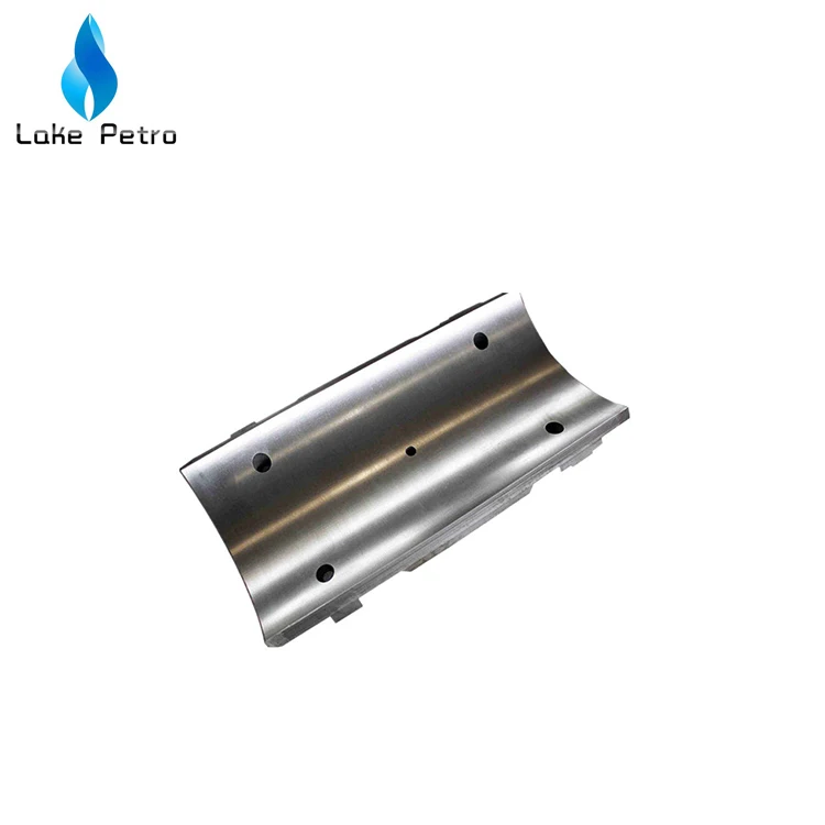
mud pump slide lower free sample
It is known to use pumps to provide drilling mud under pressure in the drilling of wells. Pressurized drilling mud is delivered down a hollow drill string as the well is being drilled to carry away cuttings up the annulus surrounding the drill string to ground level. Such drilling operations are well known to those skilled in the art.
Prior art pumps can use a motor to turn a crankshaft or “pump shaft” to convert rotary motion to a reciprocating motion. The pump shaft moves a connecting rod coupled to a crosshead that moves within a fixed crosshead slide to provide this conversion. The crosshead is coupled to a “pony rod” that, in turn, is coupled to a piston rod that provides the pumping motion in a pump module, as well known to those skilled in the art.
The above-mentioned mechanical arrangement can be multiplied so that a multitude or plurality of pump modules can be operated from a single pump shaft. The outputs of each pump module can be coupled to a common manifold from which pressurized drilling mud can be provided to the drill string. By coupling the pump module outputs to a common manifold, the pulsing of the pressure of the drilling mud can be reduced or smoothed out, this being a problem well known to those skilled in the art. The disadvantage of this mechanical arrangement is the size and complexity of the components involved to provide a multi-module pump.
It is also known in the oil and gas industry to drill horizontal wells. These are wells that are initially drilled vertically and, with the use of directional drilling equipment as well known to those skilled in the art, the direction of drilled well becomes horizontal or parallel with the ground surface. It is known to drill horizontal wells 5000 to 7500 feet in length or more. To do so requires the use of “mud motors”, motors that are powered by the delivery of highly pressurized drilling mud pumped through the drill string so as to enable the turning of the drill bit. It is also known that to drill such wells, drilling operators will use at least two or more conventional mud pumps powered by 1000 horsepower or more motors. Each mud pump is housed in its own pump house and occupies space at the drilling site. As each additional pump house increases the number of structures at a drilling site, the number of truckloads required to deliver the necessary equipment to a drilling site also increases. All this additional equipment and number of truckloads to deliver the equipment add cost to the drilling of the well.
It is, therefore, desirable to provide a pump that can convert rotary motion to reciprocating motion without having to use connecting rods, crossheads, crosshead slides and pony rods to reduce its size, complexity and cost to manufacture. It is also desirable to provide a mud pump that is compact in size but can deliver pressurized mud at a volume equivalent to two or more conventional mud pumps.
A pump is provided that comprises a pump shaft having at least one eccentric lobe that is substantially circular. A motor is used to provide the rotational power to the pump shaft. In one embodiment, the motor can be coupled directly to the pump shaft. In another embodiment, a transmission can be used between the motor and the pump shaft to reduce the angular speed of the rotational power provided to the pump shaft. In a representative embodiment, a one or two-stage gear transmission can be used. In a further embodiment, the motor can be a 3-phase AC motor controlled by a variable frequency drive mechanism to control the speed of the motor.
In one embodiment of the pump, the eccentric lobe can be rotatably disposed within a connecting rod having a substantially circular opening to receive the lobe at one end with the other end rotatably pinned to a slide configured to move in a horizontal and linear manner. In one embodiment, the slide can be slidably disposed within a pair of slide support plates that constrains the slide to move in a linearly and horizontal or side-to-side manner. In one embodiment, slide-bearing mechanisms can be disposed between the slide and the support plates so that the slide can move side-to-side with minimal friction. In a representative embodiment, the slide-bearing mechanism can further comprise means for adjusting a loading force on the slide-bearing mechanism against the slide so that the slide is further constrained to horizontal and linear movement.
As the lobe rotates within the connecting rod opening, the connecting rod slide can move up and down thereby moving the slide linearly and horizontally between the slide support plates. As the slide frame moves side to side, it can move a piston rod in and out to operate a pump module. By virtue of this configuration, the slide can have a piston rod operatively coupled to one or both opposing sides of the slide. Therefore, a single slide can operate one or two pump modules at the same time. In a further embodiment, the pump shaft can comprise a plurality of eccentric lobes thereby allowing a plurality of slides to be operated by the lobes and, hence, a plurality of pump modules to be operated from a single rotating pump shaft.
Broadly stated, in some embodiments, a mud pump is provided, comprising: a frame; at least one pump module disposed on the frame, the at least one pump module comprising an inlet port and an outlet port; a pump shaft rotatably disposed in the frame for receiving rotational power from a motor, the pump shaft having at least one substantially circular eccentric lobe disposed thereon, the centre of the at least one eccentric lobe displaced or offset from the longitudinal axis of the pump shaft; at least one slide disposed in the frame, the at least one slide operatively configured to move linearly side-to-side within the frame; at least one piston rod assembly operatively coupling the at least one slide to the at least one pump module; and a connecting rod comprising first and second ends operating coupling the pump shaft to the at least one slide, the first end rotatably disposed on the at least one eccentric lobe, the second end rotatably pinned to the at least one slide whereby rotation of the pump shaft causes the slide to move side-to-side that, in turn, causes the at least one piston rod assembly to operate the at least one pump module.
Broadly stated, in some embodiments, a mud pump is provided, comprising: a platform; a lattice frame disposed on the platform; at least one pump module disposed on the frame, the at least one pump module comprising an inlet port and an outlet port; a pump shaft rotatably disposed in the frame for receiving rotational power from a motor, the pump shaft having at least one substantially circular eccentric lobe disposed thereon, the centre of the at least one eccentric lobe displaced or offset from the longitudinal axis of the pump shaft; a motor operatively coupled to the pump shaft, the motor disposed on the platform; at least one slide disposed in the frame, the at least one slide operatively configured to move linearly side-to-side within the frame; at least one piston rod assembly operatively coupling the at least one slide to the at least one pump module; and a connecting rod comprising first and second ends operating coupling the pump shaft to the at least one slide, the first end rotatably disposed on the at least one eccentric lobe, the second end rotatably pinned to the at least one slide whereby rotation of the pump shaft causes the slide to move side-to-side that, in turn, causes the at least one piston rod assembly to operate the at least one pump module.
FIG. 7 is a perspective view depicting the frame of the mud pump of FIG. 1 showing only the slides, the slide bearings, the slide bearing support plates and the piston assemblies;
Referring to FIGS. 1 to 13, one embodiment of a mud pump is illustrated. In this embodiment, mud pump 10 can comprise lattice frame 18 and pump modules 24 mounted thereon. Frame 18 can further comprise mounting tabs 14 for attaching mud pump 10 to a platform, to a skid or to a pump house.
For the purposes of this specification, and as shown specifically in the figures, each pump module 24 can comprise inlet port 25, outlet port 35, top access port 37 and side access port 36. Pump module 24, as illustrated, can be any suitable pump module that is readily available to the mud pump industry and is well known to those skilled in the art. As shown in FIG. 1, pump module 24 is shown as a singular device having three pump units disposed therein. It is obvious to those skilled in the art that pump module 24 can comprise one or more pump units use in combination. Representative examples of pump module 24 are pump modules having an 800 horsepower rating as manufactured by Continental Emsco in the U.S.A. or their equivalent. Such pumps have interchangeable liners of different diameters whereby the volume of mud handled by a pump module per pump cycle can be adjusted upwards or downwards depending on the diameter of the liner. Generally speaking, the smaller the volume per pump module, the greater the pressure the mud can be pumped at.
Referring to FIG. 1, mud pump 10 is shown having cover 20 disposed on top of lattice frame 18. Input shaft 12 can be connected to a motor (not shown) to provide rotational input power to mud pump 10. In some embodiments, an internal combustion motor can be used to provide rotational input power to mud pump 10. In other embodiments, an electric motor of suitable power rating can be used. In further embodiments, a variable frequency drive mechanism (not shown) as well known to those skilled in the art can be used to control the electrical power provided to the electric motor thereby controlling the rotational speed the motor operates at to supply rotational input power to mud pump 10.
In one embodiment, mud pump 10 can comprise transmission 22 to couple shaft 12 to the operating components of mud pump 10. Transmission 22 can be a single-stage or dual-stage gear transmission to reduce the rotational speed of input shaft 12 to the required rotational speed for proper operation of pump shaft 30 rotatably disposed in mud pump 10. In other embodiments, transmission 22 can comprise a planetary gear transmission. In further embodiments, transmission 22 can comprise helical gears. In yet other embodiments, transmission 22 can comprise spur gears. Intake manifold 52, comprising inlet 54, is shown attached to pump module inlet ports 25. Outlet manifold 58, comprising couplers 62 and end caps 66, is shown attached to pump module outlet ports 35. In one embodiment, frame 18 can comprise return lines 68 that provide communication from galleys 38 to reservoir 70. When in operation, lubricating oils are used to lubricate the moving components of mud pump 10. These oils will collect in galleys 38 and return to reservoir 70 through return lines 68 to be re-circulated through mud pump 10.
Referring to FIG. 2, a rear elevation view of mud pump 10 is shown. In this figure, piston rod support bushings 31 are shown disposed on sidewalls 19 of frame 18. Piston liners 26 are shown disposed between pump modules 24 and support bushings 31. Couplers 41 can be used to couple liners 26 to support bushings 31. As noted above, liners 26 can be comprised of various diameters depending on the volume and the pressure drilling mud is to be produced by mud pump 10.
Referring to FIGS. 3 and 4, front views of mud pump 10 are shown. In this embodiment, pump modules 24 are shown with outlet ports 35 exposed having no output manifold attached thereon to show valve mechanism 39 disposed therein. In one embodiment, pump module 24 can comprise “sucker-cup” pump mechanisms as well known to those skilled in the art. In the illustrated embodiment, an output manifold (not shown) can be attached to the shown outlet ports 35 to collect drilling mud pumped by pump module 24, in addition to outlet manifold 58 shown in FIGS. 1 and 2, or it can be capped with a cover (not shown). Input ports 25 can be coupled together with intake manifold 52 that directs drilling mud into pump modules 24. In one embodiment, coolant pump 34 can be used to circulate coolant through piston liners 26 and oil pump 32 can be used to pump lubricating oil through support bushings 31 to lubricate the moving components therein, as described in more detail below and as shown in FIG. 13.
Referring to FIGS. 5 and 6, front cross-section views of mud pump 10 are shown revealing the internal components of the embodiment shown therein. In this embodiment, pump shaft 30 rotates as a result of input rotational power applied to input shaft 12 that is operatively coupled to pump shaft 30 via transmission 22 as shown in FIG. 4. In one embodiment, pump shaft 30 can comprise eccentric 80 disposed thereon and affixed thereto with pin 82. Rotatably disposed on eccentric 80 is connecting rod 84. In another embodiment, eccentric bearing 83 is disposed between eccentric 80 and connecting rod 84. In a further embodiment, connecting rod 84 is rotatably pinned to sidewall 28b(and sidewall 28aas shown in FIGS. 8 and 9) of slide 28 via pin 86. In yet another embodiment, bearing 85 can be disposed between pin 86 and connecting rod 84. In FIG. 5, eccentric 80 is shown rotating clockwise thereby moving connecting rod 84 upwards and to the right in this figure. In so doing, slide 28 is being pushed to the right. In one embodiment, slide 28 is disposed between upper support plate 44 and lower support plate 46 to help keep slide 28 moving in a horizontal linear path, and to resist the bending moment caused by the rotation of pump shaft 30 and eccentric 80. In another embodiment, upper slide bearing 43 can be disposed between upper plate 44 and slide 28, and lower slide bearing 45 can be disposed between lower plate 46 and slide 28 as a means to reduce the friction between slide 28 and upper and lower plates 44 and 46 as slide 28 moves side-to-side.
As slide 28 moves to the right, it pushes piston rod 27aand, hence, piston 40ato the right in liner 26ato push fluids in pump chamber 42aout through valve 39aoto outlet ports 35 (not shown) and outlet manifold 58 (not shown). In so doing, piston rod 27balso pulls piston 40bin liner 26bto the right thereby drawing in fluid through valve 39bifrom intake manifold 52.
In FIG. 6, eccentric 80 is shown rotated further clockwise (from FIG. 5) thereby moving connecting rod 84 downward and to the left. In so doing, piston 40ais being pulled to the left thereby drawing in fluid into pump chamber 42athrough valve 39aifrom intake manifold 52 while piston 40bis pushed to the left thereby pushing fluid out of pump chamber 42bthrough valve 39boto outlet ports 35 (not shown) and outlet manifold 58 (not shown). In this figure, the connecting rods 84 of two adjacent stages rising above the top of frame 18.
Referring to FIG. 7, mud pump 10 is shown without pump modules 24, cover 22, piston liners 26, pump shaft 30, slides 28 and connecting rods 84. In this illustrated embodiment, frame sidewalls 19 are visible as are removable caps 17, which are configured hold pump shaft 30 in place in frame 18. Also visible are piston rods 27, rod support bushings 31, couplers 41 and pistons 40. In one embodiment, mud pump 10 can comprise means for applying a loading force to upper support plates 44 to keep slide 28 confined to a horizontally linear range of motions. In some embodiments, these means can comprise a plurality of setscrew rails 48 disposed on frame 18 near sidewalls 19 and disposed on caps 17. In further embodiments, setscrew rails 48 can comprise a plurality of setscrews 47 threadably attached to and through said setscrew rails. Setscrews 47 can be tightened to apply forces to various locations on upper support plates 44 whereby the loading force applied to upper support plates can be adjusted at each location of setscrews 47 to ensure that slide 28 is constrained to horizontal linear movement. While the illustrated embodiment shows setscrews 47 as being manually adjustable for applying force to slide 28, it is obvious to those skilled in the art that mud pump 10 can comprise further means for monitoring the movement of slides 28 and for automatically adjusting setscrews 47 with electro-mechanical servo motors, or the like, so that setscrews 47 are dynamically adjusted in real-time to ensure that proper force is being applied to slide 28 at all times to keep its movement linearly horizontal.
Referring to FIG. 8, the mud pump 10 of FIG. 7 is now shown with frame 18 removed to reveal slides 28. In some embodiments, each slide 28 can comprise a pair of substantially parallel spaced-apart sidewalls 28aand 28b, as shown in FIGS. 8, 9 and 10. In this embodiment, slides 28 can comprise openings 29 disposed through sidewalls 28aand 28bfor pump shaft 30 (not shown) to pass through and pin openings 88 disposed through sidewalls 28aand 28bthat are configured to receive connecting rod pins 86 (not shown). In some embodiments, mud pump 10 can further comprise one or more eccentric rods 49 disposed beneath lower support plates 46 for applying upwards force thereto for ensuring that slide 28 is constrained to horizontal linear movement. This is also shown in FIGS. 9, 10, 11 and 12. In some embodiments, eccentric rods 49 can be rotated or adjusted and then set into position by turning rod adjusters 50. While the illustrated embodiment shows eccentric rods 49 as being manually adjustable for applying force to slide 28, it is obvious to those skilled in the art that mud pump 10 can comprise further means for monitoring the movement of slides 28 and for automatically adjusting eccentric rods 49 with electro-mechanical servo motors, or the like, operatively coupled to rod adjusters 50 so that eccentric rods 49 are dynamically adjusted in real-time to ensure that proper force is being applied to slide 28 at all times to keep its movement linearly horizontal.
Referring to FIG. 13, a cross-section view is shown of the internal pumping mechanism of mud pump 10. In some embodiments, piston rod 27 can be coupled to slide 28 by threading piston rod 27 into threaded opening 91 disposed on slide 28. In other embodiments, piston rod 27 can be further secured with lock nut 101 threaded on piston rod 27 and tightened against slide 28. In yet further embodiments, piston rod stud 92 can be disposed in an opening disposed through piston rod 27 and secured to slide 28 in threaded opening 93. In some embodiments, piston rod stud 92 can further comprise flange 95 that can rest against shoulder 94 disposed within piston rod 27. Piston rod stud 92 can also serve as means for mounting piston 40 and piston retaining caps 96 and 97 thereon. Nut 98 can be used to secure piston 40 and caps 96 and 97 on piston rod stud 92.
In some embodiments, mud pump 10 can comprise means for circulating coolant in piston liner 26 behind piston 40 to prevent overheating of the mechanism when in operation. As shown in FIG. 13, coolant can be pumped by coolant pump 34 (as shown in FIG. 4) into liner chamber 106 through coolant inlet 102 via lines, hoses or piping (not shown). Coolant can the flow through, and circulate within, chamber 106 and then exit through coolant outlet 104. Lines, hoses and piping (not shown) can be coupled to outlet 104 so that the heated coolant can be collected, cooled and re-circulated. In other embodiments, inlet 102 and outlet 104 can further comprise one-way valves, such as ball-valves as one example obvious to those skilled in the art, such that coolant can be drawn into chamber 106 through inlet 102 as piston 40 is moving towards pump module 24 (not shown), and then expelled from chamber 106 through outlet 104 and piston 40 is moving away from pump module 24.
In some embodiments, mud pump 10 can comprise means for circulating lubricating oil to piston rod 27 as it reciprocates back and forth through support bushing 31. As shown in FIG. 13, lubricating oil can be pumped by oil pump 32 (as shown in FIG. 4) into oil inlet 108 where it can flow into annulus 110 between piston rod 27 and support bushing 31 thereby maintaining a layer of lubricating oil therebetween. Oil can then flow out of annulus 110 into galleys 38 (as shown in FIG. 1) where the oil can be collected and re-circulated. In other embodiments, barrier seals 99 and ice-breaker wear band 100 can be disposed between piston rod 27 and support bushing 31 as sealing means to separate and isolate chamber 106 from annulus 110 so that coolant does not intermingle with and contaminate the lubricating oil, and vice-versa.
In the embodiments illustrated the figures herein, there are three slides 28 shown, each coupled to two pump modules 24 thereby resulting in the operation of six pump modules. It is obvious to those skilled in the art that fewer or more slides mechanisms can be implemented to either decrease or increase the number of pump modules that can be operated. It is also obvious to those skilled in the art that a slide frame can be releasably coupled to a single piston rod to, therefore, operate a single pump module.
Referring to FIG. 6, pump shaft 30 is shown turning three connecting rods 84. This necessarily requires pump shaft 30 having three eccentric lobes 80. In this configuration, the lobes can be displaced nominally 120° apart from each other such that the lobes can be substantially spaced equally apart around the circumference of pump shaft 30. In embodiments where pump shaft 30 comprises two eccentric lobes 80, the lobes can be displaced nominally 180° apart. In other embodiments where pump shaft 30 comprises two lobes 80, one lobe 80 can be displaced 178° from the other lobe 80 so that pump shaft 30 can more easily turn from a dead stop. In other embodiments where additional eccentric lobes are disposed on pump shaft 30, the lobes can be substantially spaced equally apart on pump shaft 30. For example, for a four-lobe shaft, each lobe 80 can be displaced 90° nominally from each other lobe 80. If five lobes are disposed on pump shaft 30, the lobes can be displaced nominally 72° apart on pump shaft 30. For six lobes disposed on pump shaft 30, the lobes can be displaced nominally 60° apart, and so on.
In operation, mud can be supplied to inlet 54 on intake manifold 52 from an external pump (not shown) drawing mud from a mud tank (not shown) as well known to those skilled in the art. As slides 28 operate pump modules 24, mud is drawn into pump modules 24 from intake manifold 52 and pumped out of pump modules 24 into outlet manifold 58 via outlet manifold couplers 62 disposed between pump modules 24 and outlet manifold 58. The pumped mud can exit outlet manifold 58 via outlet 60 that can be connected to a mud delivery pipe and/or hose for use on a drilling rig (not shown) as well known to those skilled in the art. In one embodiment, the diameter of inlet 54 and the pipe that make up intake manifold 52 can be nominally ten inches whereas the diameter of outlet and the pipe that make up outlet manifold 58 can be nominally four inches. In another embodiment, outlet manifold 58 can comprise couplings (not shown) for connection with a pressure gauge to provide a visual indication of the pressure of the mud being pumped and/or a pressure relief valve to provide means to limit the pressure of the mud being pumped by mud pump 50. It is obvious to those skilled in the art that the diameters of inlet 54, intake manifold 52, outlet manifold 58 or outlet 60 can be increased or decreased depending on the volume and pressure of drilling mud required in the drilling of a well.
In operation, it is expected that mud pump 10 can operate up to 65 revolutions per minute using a 1000 horsepower motor, which translates up to 130 pump module strokes per minute per slide frame mechanism given that each slide frame can be coupled to two pump modules. It is also anticipated that mud pump 10 can pump up to 800 gallons or 4 cubic meters of drilling mud per minute. Using 7-inch liners in the pump modules, it is expected that mud pump 10 can pump mud up to 1500 pounds per square inch in pressure. It is also expected that mud pump 10 would weigh approximately 45,000 pounds and deliver the equivalent volume and pressure of drilling mud as a conventional mud pump powered by a 1600 horsepower motor weighing up to 120,000 pounds.
Referring to FIG. 14, mud pump 10 is shown positioned in pump house 56, a structure used to house mud pumps at drilling sites. Access to mud pump 10 is done through doorways 64. In this configuration, mud pump 10, with electric motor 87 coupled to mud pump 10 via transmission 22, is positioned “lengthwise” in pump house 56. Referring to FIG. 15, the combination of mud pump 10 and motor 87 is shown in pump house 56 rotated 90 degrees. The compactness of mud pump 10 can allow it to be installed in this manner in pump house 56 whereby access to the inlet and outlet to mud pump 10 is through doorway 64. In addition, more than one mud pump 10 can be installed in pump house 56 thereby reducing the number of pump houses required at a drilling site if the well being drilled requires a volume of pressurized drilling mud greater than what one mud pump 50 can provide.

You might even have a presentation you’d like to share with others. If so, just upload it to PowerShow.com. We’ll convert it to an HTML5 slideshow that includes all the media types you’ve already added: audio, video, music, pictures, animations and transition effects. Then you can share it with your target audience as well as PowerShow.com’s millions of monthly visitors. And, again, it’s all free.
A well-placed suction stabilizer can also prevent pump chatter. Pump chatter occurs when energy is exchanged between the quick opening and closing of the reciprocating pump’s valves and the hammer effect from the centrifugal pump. Pump isolation with suction stabilizers is achieved when the charge pumps are isolated from reciprocating pumps and vice versa. The results are a smooth flow of pumped media devoid of agitating energies present in the pumped fluid.
Deep water drilling from a floating vessel typically involves the use of a large- diameter marine riser, e.g. a 21 -inch marine riser, to connect the floating vessel"s surface equipment to a blowout preventer stack on a subsea wellhead. The floating vessel may be moored or dynamically positioned at the drill site. However, dynamically-positioned drilling vessels are predominantly used in deep water drilling. The primary functions of the marine riser are to guide the drill string and other tools from the floating vessel to the subsea wellhead and to conduct drilling fluid and earth-cuttings from a subsea well to the floating vessel. The marine riser is made up of multiple riser joints, which are special casings with coupling devices that allow them to be interconnected to form a tubular passage for receiving drilling tools and conducting drilling fluid. The lower end of the riser is normally releasably latched to the blowout preventer stack, which usually includes a flexible joint that permits the riser to angularly deflect as the floating vessel moves laterally from directly over the well. The upper end of the riser includes a telescopic joint that compensates for the heave of the floating vessel. The telescopic joint is secured to a drilling rig on the floating vessel via cables that are reeved to sheaves on riser tensioners adjacent the rig"s moon pool. The riser tensioners are arranged to maintain an upward pull on the riser. This upward pull prevents the riser from buckling under its own weight, which can be quite substantial for a riser extending over several hundred feet. The riser tensioners are
The maximum practical water depth for current drilling practices with a large diameter marine riser is approximately 7,000 feet. As the need to add to energy reserves increases, the frontiers of energy exploration are being pushed into ever deeper waters, thus making the development of drilling techniques for ever deeper waters increasingly more important. However, several aspects of current drilling practices with a conventional marine riser inherently limit deep water drilling to water depths less than approximately 7,000 feet. The first limiting factor is the severe weight and space penalties imposed on a floating vessel as water depth increases. In deep water drilling, the drilling fluid or mud volume in the riser constitutes a majority of the total mud circulation system and increases with increasing water depth. The capacity of the 21 -inch marine riser is approximately 400 barrels for every 1,000 feet. It has been estimated that the weight attributed to the marine riser and mud volume for a rig drilling at a water depth of 6,000 feet is 1,000 to 1,500 tons. As can be appreciated, the weight and space requirements for a drilling rig that can support the large volumes of fluids required for circulation and the number of riser joints required to reach the seafloor prohibit the use of the 21 -inch riser, or any other large-diameter riser, for drilling at extreme water depths using the existing offshore drilling fleet.
In addition, before disconnecting the riser from the blowout preventer stack, operations must take place to condition the well so that the well may be safely abandoned. This is required because the well depends on the hydrostatic pressure of the mud column extending from the top end of the riser to the bottom of the well to
overcome the pore pressures of the formation. When the mud column in the riser is removed, the hydrostatic pressure gradient is significantly reduced and may not be sufficient to prevent formation fluid influx into the well. Operations to contain well pressure may include setting a plug, such as a storm packer, in the well and closing the blind ram in the blowout preventer stack.
The well hydrostatic pressure gradient derived from the riser height is trapped below the closed blind rams when the riser is disconnected. Thus, the only barrier to the influx of formation fluid into the well is the closed blind rams since the column of mud below the blind rams is insufficient to prevent influx of formation fluid into the well. Prudent drilling operations require two independent barriers to prevent loss of well control. When the riser is disconnected from the blowout preventer stack, large volumes of mud will be dumped onto the seafloor. This is undesirable from both an economic and environmental standpoint.
These sediments are significantly influenced by the overlying body of water and the circulating mud column need only be slightly denser than seawater to fracture the formation. Fortunately, because of the higher bulk density of the rock, the fracture pressure rapidly increases with the depth of penetration below the seafloor and will present a less serious problem after the first few thousand feet are drilled. However, abnormally high pore pressures which are routinely encountered up to 2,000 feet below the seafloor continue to present a problem both when drilling the initial section of the well with seawater and when drilling beyond the initial section of the well with seawater or weighted drilling fluid. The challenge then becomes balancing the internal pressures of the formation with the hydrostatic pressure of the mud column while continuing drilling of the well. The current practice is to progressively run and cement casings, the next inside the previous, into the hole to protect the "open hole" sections possessing insufficient fracture pressure while allowing weighted drilling fluids to be used to overcome formation pore pressures. It is important that the well be completed with the largest practical casing through the production zone to allow production rates that will justify the high-cost of deep-water developments. Production rates exceeding 10,000 barrels per day are common for deep-water developments, and too small a production casing would limit the productivity of the well, making it uneconomical to complete. The number of casings run into the hole is significantly affected by water depth.
The multiple casings needed to protect the "open hole" while providing the largest practical casing through the production zone requires that the surface hole at the seafloor be larger. A larger surface hole in turn requires a larger subsea wellhead and blowout preventer stack and a larger blowout preventer stack requires a larger marine riser. With a larger riser, more mud is required to fill the riser and a larger drilling vessel is required to carry the mud and support the riser. This cycle repeats itself as water depth increases.
It has been identified that the key to breaking this cycle lies in reducing the hydrostatic pressure of the mud in the riser to that of a column of seawater and providing mud with sufficient weight in the well to maintain well control. Various concepts have
been presented in the past for achieving this feat; however, none of these concepts known in the prior art have gained commercial acceptance for drilling in ever deeper waters. These concepts can be generally grouped into two categories: the mud lift drilling with a marine riser concept and the riserless drilling concept. The mud lift drilling with a marine riser concept contemplates a dual-density mud gradient system which includes reducing the density of the mud returns in the riser so that the return mud pressure at the seafloor more closely matches that of seawater. The mud in the well is weighted to maintain well control. For example, U.S. Patent No. 3,603,409 to Watkins et al. and U.S. Patent No. 4,099,583 to Maus et al. disclose methods of injecting gas into the mud column in the marine riser to lighten the weight of the mud.
The riserless drilling concept contemplates eliminating the large-diameter marine riser as a return annulus and replacing it with one or more small-diameter mud return lines. For example, U.S. Patent No. 4,813,495 to Leach removes the marine riser as a return annulus and uses a centrifugal pump to lift mud returns from the seafloor to the surface through a mud return line. A rotating head isolates the mud in the well annulus from the open seawater as the drill string is run in and out of the well.
Drilling rates are significantly affected by the magnitude of the difference between formation pore pressure and mud column pressure. This difference, commonly called "overbalance", is adjusted by changing the density of the mud column. Overbalance is estimated as the additional pressure required to prevent the well from kicking, either during drilling or when pulling a drill string out of the well. This overbalance estimate usually takes into account factors like inaccuracies in predicting formation pore pressures and pressure reductions in the well as a drill string is pulled from the well. Typically, a minimum of 300 to 700 psi overbalance is maintained during drilling operations. Sometimes the overbalance is large enough to damage the formation.
the overbalance is reduced to zero. An even greater increase in drilling rate can be achieved if the mud column pressure is decreased to an underbalanced condition, i.e. mud column pressure is less than formation pressure. Thus, to improve drilling rates, it may be desirable to drill a well in an underbalanced mode or with a minimum of overbalance. In conventional drilling operations, it is impractical to reduce the mud density to allow faster drilling rates and then increase the mud density to permit tripping the drill string. This is because the circulation time for the complete mud system lasts for several hours, thus making it expensive to repeatedly decrease and increase mud density. Furthermore, such a practice would endanger the operation because a miscalculation could result in a kick.
In general, in one aspect, a positive-displacement pump comprises multiple pumping elements, each pumping element comprising a pressure vessel with a first and a second chamber and a separating member disposed between the first and second chambers. The first chambers and the second chambers are hydraulically connected to receive and discharge fluid, wherein the separating members move within the pressure vessels in response to pressure differential between the first and second chambers. A valve assembly having suction and discharge valves communicates with the first chambers. The suction and discharge valves are operable to permit fluid to alternately flow into and out of the first chambers. A hydraulic drive alternately supplies hydraulic fluid to and withdraws hydraulic fluid from the second chambers such that the fluid discharged from the first chambers is substantially free of pulsation.
FIG. 2A is a detailed view of the well control assembly shown in FIG. 1. FIG. 2B is a detailed view of the mud lift module shown in FIG. 1. FIG. 2C is a detailed view of the pressure-balanced mud tank shown in FIG. 1.
FIG. 8 is an elevation view of a subsea mud pump. FIG. 9A is a cross section of a diaphragm pumping element. FIG. 9B is a cross section of a piston pumping element.
FIG. 16 is a diagram of a mud circulation system for the offshore drilling system shown in FIG. 1. FIG. 17 is a graph of depth versus pressure for a well drilled in a water depth of
FIG. 20A is a graph of depth versus pressure for a well drilled in a water depth of 5,000 feet for a dual-density mud gradient system which has a mudline pressure less than seawater pressure.
FIG. 21 illustrates the offshore drilling system of FIG. 1 with a mud lift module mounted on the seafloor. FIGS. 22A and 22B are elevation views of retrievable subsea components of the offshore drilling system shown in FIG. 21.
FIG. 26 is a top view of another embodiment of the return line riser shown in FIG. 23. FIG. 27 illustrates the offshore drilling system of FIG. 1 without a marine riser and with a mud lift module mounted on the seafloor.
A drilling rig 20 is positioned in the middle of the drilling vessel 12, above a moon pool 22. The moon pool 22 is a walled opening that extends through the drilling vessel 12 and through which drilling tools are lowered from the drilling vessel 12 to the seafloor 17. At the seafloor 17, a conductor pipe 32 extends into a well 30. A conductor housing 33, which is attached to the upper end of the conductor pipe 32, supports the conductor pipe 32 before the conductor pipe 32 is cemented in the well 30. A guide structure 34 is installed around the conductor housing 33 before the conductor housing 33 is run to the seafloor 17. A wellhead 35 is attached to the upper end of a surface pipe 36 that extends through the conductor pipe 32 into the well 30. The wellhead 35 is of conventional design and provides a method for hanging additional casing strings in the well 30. The wellhead 35 also forms a structural base for a wellhead stack 37.
The wellhead stack 37 includes a well control assembly 38, a mud lift module 40, and a pressure-balanced mud tank 42. A marine riser 52 between the drilling rig 20 and the wellhead stack 37 is positioned to guide drilling tools, casing strings, and other equipment from the drilling vessel 12 to the wellhead stack 37. The lower end of the marine riser 52 is releasably latched to the pressure-balanced mud tank 42, and the upper end of the marine riser 52 is secured to the drilling rig 20. Riser tensioners 54 are provided to maintain an upward pull on the marine riser 52. Mud return lines 56 and 58, which may be attached to the outside of the marine riser 52, connect flow outlets (not shown) in the mud lift module 40 to flow ports in the moon pool 22. The flow ports in the moon pool 22 serve as an interface between the mud return lines 56 and 58 and a mud return system (not shown) on the drilling vessel 12. The mud return lines 56 and 58 are also connected to flow outlets (not shown) in the well control assembly 38, thus allowing them to be used as choke/kill lines. Alternatively, the mud return lines 56 and 58 may be existing choke/kill lines on the riser.
A drill string 60 extends from a derrick 62 on the drilling rig 20 into the well 30 through the marine riser 52 and the wellhead stack 37. Attached to the end of the drill string 60 is a bottom hole assembly 63, which includes a drill bit 64 and one or more drill collars 65. The bottom hole assembly 63 may also include stabilizers, mud motor, and
other selected components required for drilling a planned trajectory, as is well known in the art. During normal drilling operations, the mud pumped down the bore of the drill string 60 by a surface pump (not shown) is forced out of the nozzles of the drill bit 64 into the bottom of the well 30. The mud at the bottom of the well 30 rises up the well annulus 66 to the mud lift module 40, where it is diverted to the suction ends of subsea mud pumps (not shown). The subsea mud pumps boost the pressure of the returning mud flow and discharge the mud into the mud return lines 56 and/or 58. The mud return lines 56 and/or 58 then conduct the discharged mud to the mud return system (not shown) on the drilling vessel 12. The drilling system 10 is illustrated with two mud return lines 56 and 58, but it should be clear that a single mud return line or more than two mud return lines may also be used. Clearly the diameter and number of the return lines will affect the pumping requirements for the subsea mud pumps in the mud lift module 40. The subsea mud pumps must provide enough pressure to the returning mud flow to overcome the frictional pressure losses and the hydrostatic head of the mud column in the return lines. The wellhead stack 37 includes subsea diverters (not shown) which seal around the drill string 60 and form a separating barrier between the riser 52 and the well annulus 66. The riser 52 is filled with seawater so that the hydrostatic pressure of the fluid column at the seafloor or mudline or separating barrier formed by the subsea diverters is that of seawater. Filling the riser with seawater, as opposed to mud, reduces the riser tension requirements. The riser may also be filled with other fluids which have a lower specific gravity than the mud in the well annulus.
Well Control Assembly FIG. 2A shows the components of the well control assembly 38 which was previously illustrated in FIG. 1. As shown, the well control assembly 38 includes a lower marine riser package (LMRP) 44 and a subsea blowout preventer (BOP) stack 46. The BOP stack 46 includes a pair of dual ram preventers 70 and 72. However, other combinations, such as, a triple ram preventer combined with a single ram preventer may
be used. Additional preventers may also be required depending on the preferences of the drilling operator. The ram preventers are equipped with pipe rams for sealing around a pipe and shear/blind rams for shearing the pipe and sealing the well. The ram preventers 70 and 72 have flow ports 76 and 78, respectively, that may be connected to choke/kill lines (not shown). A wellhead connector 88 is secured to the lower end of the ram preventer 70. The wellhead connector 88 is adapted to mate with the upper end of the wellhead 35 (shown in FIG. 1).
The LMRP 44 includes annular preventers 90 and 92 and a flexible joint 94. However, the LMRP 44 may take on other configurations, e.g., a single annular preventer and a flexible joint. The annular preventers 90 and 92 have flow ports 98 and 100 that may be connected to choke/kill lines (not shown). The lower end of the annular preventer 90 is connected to the upper end of the ram preventers 72 by a LMRP connector 93. The flexible joint 94 is mounted on the upper end of the annular preventer 92. A riser connector 114 is attached to the upper end of the flexible joint 94. The riser connector 114 includes flow ports 113 which may be hydraulically connected to the flow ports 76, 78, 98, and 100. The LMRP 44 includes control modules (not shown) for operating the ram preventers 70 and 72, the annular preventers 90 and 92, various connectors and valves in the wellhead stack 37, and other controls as needed. Hydraulic fluid is supplied to the control modules from the surface through hydraulic lines (not shown) that may be attached to the outside of the riser 52 (shown in FIG. 1).
Mud lift module FIG. 2B shows the components of the mud lift module 40 which was previously illustrated in FIG. 1. As shown, the mud lift module 40 includes subsea mud pumps 102, a flow tube 104, a non-rotating subsea diverter 106, and a rotating subsea diverter 108. The lower end of the flow tube 104 includes a riser connector 110 which is adapted to mate with the riser connector 114 (shown in FIG. 2 A) at the upper end of the flexible joint 94. When the riser connector 110 mates with the riser connector 114, the flow ports 111 in the riser connector 110 are in communication with the flow ports 113 (shown in
FIG. 2 A) in the riser connector 114. A riser connector 112 is mounted at the upper end of the subsea diverter 108. The flow ports 111 in the riser connector 110 are connected to flow ports 116 in the riser connector 112 by pipes 118 and 120, and the pipes 118 and 120 are in turn hydraulically connected to the discharge ends of the subsea mud pumps 102. The suction ends of the subsea mud pumps 102 are hydraulically connected to flow outlets 125 in the flow tube 104.
The subsea diverters 106 and 108 are arranged to divert mud from the well annulus 66 (shown in FIG. 1) to the suction ends of the subsea mud pumps 102. The diverters 106 and 108 are also adapted to slidingly receive and seal around a drill string, e.g., drill string 60. When the diverters seal around the drill string 60, the fluid in the flow tube 104 or below the diverters is isolated from the fluid in the riser 52 (shown in FIG. 1) or above the diverters. The diverters 106 and 108 may be used alternately or together to sealingly engage a drill string and, thereby, isolate the fluid in the annulus of the riser 52 from the fluid in the well annulus 66. It should be clear that either the diverter 106 or 108 may be used alone as the separating medium between the fluid in the riser 52 and the fluid in the well annulus 66. A rotating blowout preventer (not shown), which could be included in the well control assembly 38 (shown in FIG. 2 A), may also be used in place of the diverters. The diverter 108 may also be mounted on the annular preventer 92 (shown in FIG. 2 A), and mud flow into the suction ends of the subsea pumps 102 may be taken from a point below the diverter.
The stripper element 286 includes a stripper rubber 288 that is bonded to a metal body 290. The locks 284 slide into recesses 291 in the metal body 290 to lock the metal body 290 in place inside the housing body 272. A seal 292 on the metal body 290 forms a seal between the housing body 272 and the metal body 290. The stripper rubber 288 sealingly engages a drill string that is received inside the bore 278 while permitting the drill string to rotate and move axially inside the bore 278. The stripper rubber 288 does not rotate with the drill string so the rubber 288 is subjected to friction forces associated with both the rotational and vertical motions of the drill string. The stripper element 286 may be carried into and out of the housing body 272 on a handling tool which may be positioned above the bottom hole assembly of the drill string.
A retrievable spindle 178 is disposed in the bore 168 of the housing body 162. The spindle 178 has an upper portion 180 and a lower portion 182. The upper portion 180 has recesses 181 into which the locks 176 may slide to lock the upper portion 180 in place inside the housing body 162. A seal 183 on the upper portion 180 seals between the housing body 162 and the upper portion 180. A bearing assembly 184 is attached to the upper portion 180. The bearing assembly 184 has bearings which support the lower portion 182 of the spindle 178 for rotation inside the housing body 162. A stripper rubber 185 is bonded to the lower portion 182 of the spindle 178. The stripper rubber 185 rotates with and sealingly engages a drill string (not shown) that is received in the bore 168 while permitting the drill string to move vertically.
In operation, the spindle 178 is carried into the housing body 162 on a handling tool that is mounted on the drill string. When the spindle 178 lands on the shoulder 174, the drill string is rotated until the locks 176 are aligned with the recesses 181 in the upper portion 180 of the spindle 178. Then the hydraulic actuators 177 are operated to push the locks 176 into the recesses 181. The stripper rubber 185 seals against the drill string while allowing the drill string to be lowered into the well. During drilling, friction between the rotating drill string and the stripper rubber 185 provides sufficient force to rotate the lower portion 182 of the spindle 178. While the lower portion 182 is rotated, the stripper rubber 185 is only subjected to the friction forces associated with the vertical motion of the drill string. This has the effect of prolonging the wear life of the stripper rubber 185. When the drill string is pulled out of the well, the hydraulic actuators 177 may be operated to release the locks 176 from the recesses 181 so that the handling tool on the drill string can engage the spindle 178 and pull the spindle 178 out of the housing body 162. FIG. 4B shows a vertical cross section of another rotating subsea diverter, i.e., rotating subsea diverter 186, that may be used in place of the rotating subsea diverter 108. The subsea diverter 186 includes a retrievable spindle 188 which is disposed in a housing body 190. The spindle 188 includes two opposed stripper rubbers 192 and 194. The stripper rubber 192 is oriented to effect a seal around a drill string when the pressure
As shown in FIG. 4E, the spindle assembly 1740 further comprises a spindle 1760 which extends through the spindle housing 1742. The spindle 1760 is suspended in the spindle housing 1742 by bearings 1762 and 1764. The bearing 1762 is secured between the spindle housing 1742 and the spindle 1760 by a bearing cap 1765. The spindle housing 1742, the spindle 1760, and the bearings 1762 and 1764 define a chamber 1768 which holds lubricating fluid for the bearings. The bearing cap 1765 may be removed to access the chamber 1768. Pressure intensifiers 1766 are provided to boost the pressure in the chamber 1768 as necessary so that the pressure in the chamber 1768 balances or exceeds the pressure above and below the spindle 1760. Referring back to FIG. 4C, the spindle 1760 includes an upper packer element 1772, a lower packer element 1774, and a central passageway 1776 for receiving a drill string, e.g., drill string 1770.
shoulder 1778 is fully extended and the spindle assembly 1740 seats on the landing shoulder 1778. The spring force must overcome the force due to the pressure at the lower end of the spindle 1760 to keep the piston 1786 in contact with the surface 1804. If the spring force is not sufficient, fluid may be fed into the cavity 1794 at a higher pressure than the fluid pressure in the cylinder 1784. The pressure differential between the cavity 1794 and the cylinder 1784 would provide the additional force necessary to move the piston 1786 against the surface 1804 and retain the landing shoulder 1778 in the fully extended position.
A connector 1810 on the head 1712 and the mounting flange 1812 at the lower end of the body 1716 allow the diverter 1710 to be interconnected in the wellhead stack 37. In one embodiment, the mounting flange 1812 may be attached to the upper end of the flow tube 104 (shown in FIG. 2B) and the connector 1810 may provide an interface between the mud lift module 40 (shown in FIG. 2B) and the pressure-balanced mud tank 42 or the riser 52 (shown in FIG. 1). When the mounting flange 1812 is attached to the upper end of the flow tube 104, the space 1818 below the packer 1774 is in fluid communication with the well annulus 66 (shown in FIG. 1).
The diameters of the vertical bores 1714 and 1718 are such that any tool that can pass through the marine riser 52 (shown in FIG. 1) can also pass through them. The retractable landing shoulder 1778 may be retracted to allow passage of large tools and may be extended to allow proper positioning of the spindle assembly 1740 within the bores 1714 and 1718. The spindle assembly 1740 can be appropriately sized to pass through the marine riser 52 and can be run into and retrieved from the vertical bores 1714 and 1718 on a drill string, e.g., drill string 1770. As shown, a handling tool 1771 on the drill string 1770 is adapted to engage the lower packer element 1774 of the spindle 1760 such that the spindle assembly 1740 can be run into the vertical bores 1714 and 1718. When the spindle assembly 1740 lands on the landing shoulder 1774, the inner elastomeric element 1748 is energized to engage the spindle assembly 1740. Once the spindle assembly 1740 is engaged, the handling tool 1771 can be disengaged from the spindle assembly 1740 by further lowering the drill string 1770. The handling tool 1771 will again engage the spindle assembly 1740 when it is pulled to the lower packer element 1774, thus allowing the spindle assembly 1740 to be retrieved to the surface.
Pressure-Balanced Mud Tank FIG. 2C shows the pressure-balanced mud tank 42, which was previously illustrated in FIG. 1, in greater detail. As shown, the pressure-balanced mud tank 42 includes a generally cylindrical body 230 with a bore 231 running through it. The bore 231 is arranged to receive a drill string, e.g., drill string 60, a bottom hole assembly, and other drilling tools. An annular chamber 235 which houses an annular piston 236 is defined inside the body 230. The annular piston engages and seals against the inner walls 238 and 240 of the body 230 to define a seawater chamber 242 and a mud chamber 244 in the mud tank 42. The seawater chamber 242 is connected to open seawater through the port 246. This allows ambient seawater pressure to be maintained in the seawater chamber 242 at all times. Alternatively, a pump (not shown) may be provided at the port 246 to allow the pressure in the seawater chamber 242 to be maintained at, above, or below that of ambient seawater pressure. The mud chamber 244 is connected through a
The piston 236 reciprocates axially inside the annular chamber 235 when a pressure differential exists between the seawater chamber 242 and the mud chamber 244. A flow meter (not shown) aπanged at the port 246 measures the rate at which seawater enters or leaves the seawater chamber 242 as the piston 236 reciprocates inside the chamber 235. Flow readings from the flow meter provide the necessary information to determine mud level changes in the mud tank 42. A position locator (not shown) may also be provided to track the position of the piston 236 inside the annular chamber 235. The position of the piston 236 may then be used to calculate the mud volume in the mud tank 42.
A wiper 232 is mounted on the body 230. The wiper 232 includes a wiper receptacle 233 which houses a wiper element 234 (shown in FIG. 5). As shown in FIG. 5, the wiper element 234 includes a cartridge 256 which is made of a stack of multiple elastomer disks 258. The elastomer disks 258 are arranged to receive and provide a low- pressure pack-off around a drill string, e.g., drill string 60. The elastomer disks 258 also wipe mud off the drill string as the drill string is pulled through the wiper element 234. The arrangement of the elastomer disks 258 gives a step-type seal which allows each disk to contain only a fraction of the overall pressure differential across the wiper element 234. The wiper element 234 will be carried into and out of the wiper receptacle 233 on a handling tool (not shown) that is mounted on the drill string 60.
Referring back to FIG. 2C, a riser connector 260 is mounted on the wiper receptacle 233. The riser connector 260 mates with a riser connector 262 at the lower end of the marine riser 52. A riser connector 115 is also provided at the lower end of the body 230. The riser connector 115 is arranged to mate with the riser connector 112 (shown in FIG. 2B) in the mud lift module 40. Flow ports in the riser connector 115 are connected to the mud return lines 56 and 58 through the pipes 122 and 124 and flow ports in the riser connectors 260 and 262. When the riser connector 115 mates with the riser connector 112, the pipes 122 and 124 are in communication with the pipes 118 and 120.
Referring now to FIGS. 2A-2C, when the mud lift module 40, the pressure- balanced mud tank 42, and the riser 52 are mounted on the well control assembly 38, the flexible joint 94 permits angular movement of these assemblies as the drilling vessel 12 (shown in FIG. 1) moves laterally. The angular movement or pivoting of the mud lift module 40 can be prevented by removing the flexible joint 94 from the LMRP 44 and locating it between the mud lift module 40 and the pressure-balanced mud tank 42 or between the pressure-balanced mud tank 42 and the riser 52. When the flexible joint 94 is removed from the LMRP 44, the mud lift module 40 may then be mounted on the LMRP 44 by connecting the flow tube 104 to the upper end of the annular preventer 92. The height of the wellhead stack 37 (illustrated in FIG. 1) may be reduced by replacing the pressure-balanced mud tank 42 with smaller pressure-balanced mud tanks which may be incorporated with the mud lift module 40. In this embodiment, the connector 262 at the lower end of the riser 52 would then mate with the connector 112 on the rotating subsea diverter 108. Instead of directly connecting the connector 262 to the connector 112, a flexible joint, similar to the flexible joint 94, may be mounted between the connectors 112 and 262. As shown in FIG. 6, a smaller pressure-balanced mud tank 234 includes a seawater chamber 265 which is separated from a mud chamber 266 by a floating, inflatable elastomer sphere 267. Of course, any other separating medium, such as a floating piston, may be used to isolate the seawater chamber 265 from the mud chamber 266.
Seawater may enter or leave the seawater chamber 265 through a port 268. One or more pumps (not shown) may be connected to port 268 to maintain the pressure in the chamber 265 at, above, or below that of ambient seawater pressure. A flow meter (not shown) may be connected to port 268 to measure the rate at which seawater enters or leaves the seawater chamber 265. Mud may enter or be discharged from the mud chamber 266 through a port 269. The port 269 could be connected to the piping that links the well annulus to the suction ends of the subsea pumps 102 (shown in FIG. 2B) or to the flow outlet 125 in the flow tube 104 (shown in FIG. 2B). A position locator (not
The height of the wellhead stack 37 (illustrated in FIG. 1) may also be reduced by eliminating the pressure-balanced mud tank 42 and employing the riser 52 to perform the function of the pressure-balanced mud tank. As shown in FIG. 7, when the pressure- balanced mud tank 42 is eliminated, a subsea diverter, e.g., the rotating subsea diverter 1710 which was previously illustrated in FIG. 4C, may provide the interface between the mud lift module 40 and the riser 52. In this embodiment, the connector 1810 at the upper end of the rotating subsea diverter 1710 mates with the connector 262, and the mounting flange 1812 mates with the upper end of the flow tube 104. The outlet 1816 in the connector 1810 is connected to a port 1820 in the flow tube 104 by piping 1822 so that mud from the well annulus 66 may flow into the riser 52. Because the mud in the well annulus 66 is heavier than the seawater in the riser 52, the mud 1821 from the well annulus 66 will remain at the bottom of the riser 52 with the seawater 1823 floating on top. This allows the bottom of the riser 52 to function as a chamber for holding mud from the well annulus 66. Mud may be discharged from the riser 52 to the well annulus 66 as necessary. A bypass valve 1824 in the piping 1822 may be operated to control fluid communication between the well annulus 66 and the riser 52.
In another embodiment, as shown in FIG. 7B, a floating barrier 1825 which has a bore for receiving a drill string, e.g., drill string 60, may be disposed in the riser 52 to separate the seawater in the riser from the drilling mud. The floating barrier 1825 may have a specific gravity greater than the specific gravity of seawater but less than the specific gravity of the drilling mud so that it floats on the drilling mud and, thereby, separates the drilling mud 1821 from the seawater 1823. In this way, the mixing action created by rotation of the drill string in the riser can be minimized. Means, e.g., spring- loaded ribs, can be provided between the floating barrier 1825 and the riser 52 to reduce the rotation of the floating barrier within the riser. When the floating barrier 1825 is disposed in the riser 52 as shown, the diverter 1710 (shown in FIG. 7 A) may be eliminated from the mud lift module. However, it may also be desirable to use the
Referring now to FIGS. 1-5, preparation for drilling begins with positioning the drilling vessel 12 at a drill site and may include installing beacons or other reference devices on the seafloor 17. It may be necessary to provide remotely operated vehicles, underwater cameras or other devices to guide drilling equipment to the seafloor 17. The use of guidelines to guide the drilling equipment to the seafloor may not be practical if the water is too deep. After positioning of the drilling vessel 12 is completed, drilling operations usually begin with lowering the guide structure 36, conductor housing 33, and conductor pipe 32 on a running tool attached above a bottom hole assembly. The bottom hole assembly, which includes a drill bit and other selected components to drill a planned trajectory, is attached to a drill string that is supported by the drilling rig 20. The bottom hole assembly is lowered to the seafloor and the conductor pipe 32 is jetted into place in the seafloor. After jetting the conductor pipe 32 in place, the bottom hole assembly is unlocked to drill a hole for the surface pipe 36. Drilling of the hole starts by rotating the drill bit using a rotary table or a top drive. A mud motor located above the drill bit may alternatively be used to rotate the drill bit. While the drill bit is rotated, fluid is pumped down the bore of the drill string. The fluid in the drill string jets out of the nozzles of the drill bit, flushing drill cuttings away from the drill bit. In this initial drilling stage, the fluid pumped down the bore of the drill string may be seawater. After the hole for the surface pipe 36 is drilled, the drill string and the bottom hole assembly are retrieved. Then, the surface pipe 36 is run into the hole and cemented in place. The surface pipe 36 has the subsea wellhead 35 secured to its upper end. The subsea wellhead 35 is locked in place inside the conductor housing 33.
The mud lift drilling operations begin by lowering the wellhead stack 37 to the seafloor through the moon pool 22. This is accomplished by latching the lower end of the marine riser 52 to the upper end of the mud tank 42 at the top of the wellhead stack 37. Then, the marine riser 52 is run towards the seafloor 17 until the subsea BOP stack
46 at the bottom of the wellhead stack 37 lands on and latches to the wellhead 35. The seawater chamber 242 of the mud tank 42 fills with seawater as the wellhead stack 37 is lowered. The mud return lines 56 and 58 are connected to the flow ports in the moon pool 22 after the wellhead stack 37 is secured in place on the wellhead 35. The drill string 60 with the spindle 178 is lowered through the riser 52 into the housing body 162 of the stripper 108. When the spindle 178 lands on the retractable landing shoulder 174 inside the housing body 162, the drill string is rotated to allow the locks in the housing body to latch into the recesses in the spindle 178. Then the drill string is lowered to the bottom of the well through the diverter 106, the flow tube 104, and the well control assembly 38. When the drill bit 64 touches the bottom of the well 30, the surfac


 8613371530291