
mud pump slide lower brands
VigorPetro offers a full line of premium expendables and service parts for all well-known makes and models of mud pumps that are currently in operation worldwide.
These parts combine the finest materials and manufacturing expertise, including the premium service and support that VigorPetro has historically provided all our clients. The result is the best performing products available from any manufacturer. Whether you are running Brewster, Emsco, Ideco, Gardner-Denver, National, Oilwell, LEWCO, or Wirth pumps in your rig feet, VigorPetro is now a one-stop shop that can supply all the parts needed to keep these pumps running daily.
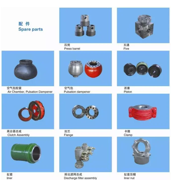
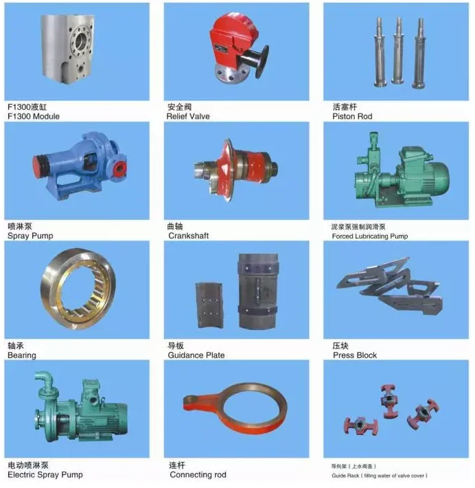
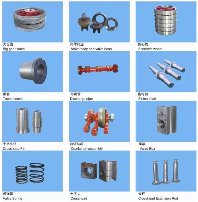
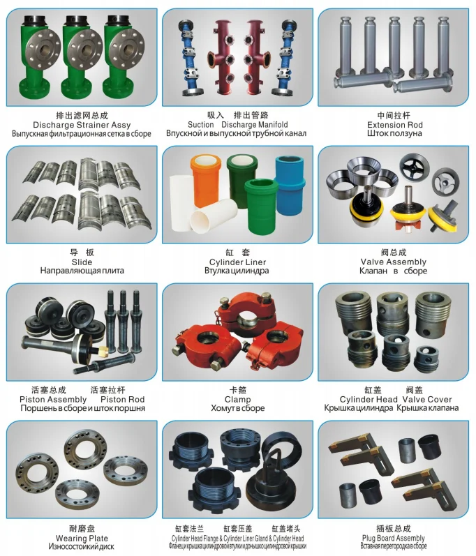
Spare parts:Upper and lower Valve Guide, Liner Gasket, Piston Rod, Rod Clamp, Valve Cover, Valve Cover Seal, Cylinder head, Cylinder Head Gasket, Cylinder Head Flange/Threaded Ring, Alignment Ring, Wear Plate, Cylinder Head Plug, Liner Flange, Liner Lock, Mud Baffle
Pony Rod/Extension Rod, Stuffing Box, Stuffing box Seal Parts, Crosshead, Crosshead Guide, Crosshead Pin, Crosshead Bearing, Connection Rod, Bull Gears, Pinion Shaft, Pinion Shaft Bearing/Bearing Carrier/Oil Seal Gasket/, Crank Shaft, Crank Shaft Bearing/Bearing Carrier, Eccentric Bearing, Inner/outer Race Retainer, Gauges, Oil Lubrication Pump, Mud Pump Transmission Belt Pulley/V-belt
Whether onshore or offshore, well drilling sites rely on a multitude of systems to successfully perform the drilling operation. The mud pump is a key component tasked with circulating drilling fluid under high pressure downhole. The mud pump can be divided into two key sections: the power end or crosshead and the fluid end. Proper alignment of the pump’s crosshead to the fluid end liner is necessary to maximizing piston and liner life. Misalignment contributes to
accelerated wear on both the piston and the liner, and replacing these components requires downtime of the pump. Traditional methods of inspecting alignment range from using uncalibrated wooden rods, Faro Arms and micrometers to check the vertical and horizontal alignment of the piston rod OD to the piston liner ID. These are time consuming and cumbersome techniques that are ultimately not well suited to troubleshoot and solve alignment issues.
A “Mud Pump Laser Alignment Kit” enables you to measure where the piston will run through the liner at various positions along the pump’s stroke. It will also project a laser centerline from the fluid end back towards the rear power end of the pump that can be used to determine how much shimming is required to correct any alignment issues. The kit can include either a 2-Axis receiver or a 4-Axis which accepts the laser beam and documents where it falls on the active surface of the receiver. The 4-Axis receiver can decrease alignment time by as much as 50% as it will measure angularity as well as X and Y while the 2-Axis does not and will need multiple measurement locations to get the same information. In addition, the alignment system is a non-intrusive service requiring the removal of only the piston rod which allows for much quicker service and less down time on the pump. As the mud pumps in question are located globally both on and offshore, having a small, portable system is another great advantage. Our recommendation would be Pinpoint laser System’s “Mud Pump Alignment Kit”. They are being used by many of the leading repair service companies and have been their main alignment tool for over 15 years. Manufacturers are also utilizing these for new pump set-up.
Houston, Texas -- To eliminate equipment compatibility issues and the prospect of additional spare-parts inventories for drilling contractors, the LeTourneau Ellis Williams Company (LEWCO) can factory-equip its heavy-duty W-Series and general-duty WH-Series mud pumps with virtually any major brand of fluid end module. Customers not specifying a particular brand receive LEWCO"s standard one-piece or two-piece fluid end modules made of quenched and tempered forged steel, featuring "off the shelf" expendables readily available from domestic and international sources.
LEWCO mud pumps are in-house manufactured. For maximum quality assurance -- with job-ready performance verified in advance -- every pump is tested under full load prior to shipment, in the company"s fully equipped, million-dollar "mud pump laboratory." LEWCO pumps provide input ratings of 300 to 3,000 horsepower (224 kW to 2,237 kW) and deep-drilling discharge pressures as great as 7,500 pounds per square inch (527 kg/cm2). Their premium components include a pressurized lubrication system that force-feeds lubricant to all power-end bearings including upper and lower crosshead slides; a balanced forged steel crankshaft that reduces noise and vibration and helps extend component life throughout the pump; and a robust frame of double-wall, welded-steel, mounted on a heavy-duty oilfield skid.
The LeTourneau Ellis Williams Company builds high-performance mud pumps for oil and gas drilling (on land and offshore), petroleum production and processing, well-servicing, and horizontal directional drilling; as well as ancillary drilling products including pulsation dampeners; drawworks; rotary tables, transmissions, and drives; and swivels. Located in Houston, Texas, LEWCO is a wholly owned subsidiary of LeTourneau Incorporated, a leading manufacturer of self-elevating offshore drilling rigs, forestry equipment, and wheel loaders.
For more information, contact the LEWCO Sales Department at 6500 Brittmoore Road, Houston, TX 77241-1343; telephone 1-888-MUD-PUMP (683-7867), fax 713-856-5341; e-mail pumps@lewco-equip.com. Or visit www.lewco-equip.com.
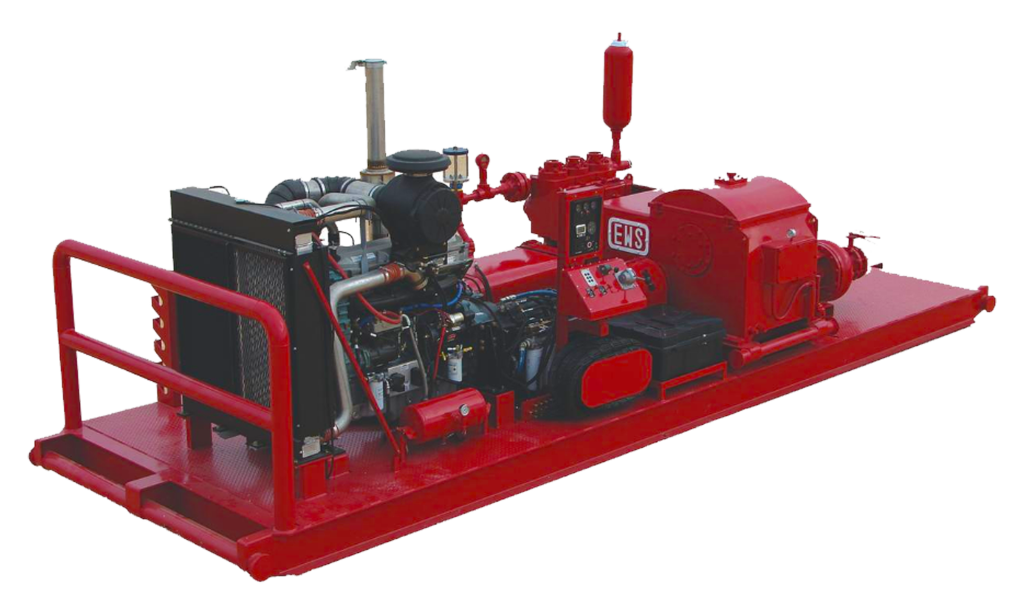
The 2,200-hp mud pump for offshore applications is a single-acting reciprocating triplex mud pump designed for high fluid flow rates, even at low operating speeds, and with a long stroke design. These features reduce the number of load reversals in critical components and increase the life of fluid end parts.
The pump’s critical components are strategically placed to make maintenance and inspection far easier and safer. The two-piece, quick-release piston rod lets you remove the piston without disturbing the liner, minimizing downtime when you’re replacing fluid parts.
All Collection30 Day Window Films3M Branded ProductsAccess DoorsAcrylic and Conventional Stucco FloatsAcrylic and Conventional Stucco ProductsAdex Acrylic StuccoAdexMat Branded ProductsAdfors Branded ProductsAir HosesAlberta Construction Safety Association Branded ProductsAluminum and Magnesium HawksAluminum and Magnesium StiltsAmerimaxAngle HeadsAS-IS BrandAs-Is Brand Wood WallAutomatic & Semi Automatic TapersAutomatic & Semi-Automatic Taping ToolsB&IBaker Scaffolding & AccessoriesBeadex Branded Paper/Metal Drywall BeadBeroXpertBlown-In InsulationBold Black Rhino Branded ProductsBossBrushes and SpongesBucket ScoopsCan-Am PartsCan-Am Taping Tools Branded ProductsCanada Drop Branded ProductsCANTECH Branded ProductsCanvas DropclothsCeiling Grid & TileCeiling Knockdown KnivesCeiling Texture CompoundCeiling Tile Tools & AccessoriesCement Board ScrewsCendrex Branded ProductsCertainTeed Branded ProductsCGC Branded ProductsCGC Concrete Fill & SealCGSB Vapour Barrier PolyChalk LinesCircle Brand Branded ProductsCO-ME Branded ProductsColumbia Taping Tool PartsColumbia Taping Tools Branded ProductsConstruction Knives, Jab Saws, & BladesCorner FlushersCoronado BrickCoronado StoneCoronado StoneCrispo CanadaCrown Equipment Branded ProductsDeck ScrewsDEGILL Branded ProductsDemand Branded ProductsDEWALT Branded ProductsDolphin Branded ProductsDONN Branded ProductsDoor, Window, & Joint MembranesDOW Branded ProductsDropped Ceiling Tools, Knockdown Knives and Texture GunsDrywall Adhesive, Compound, Primer & Joint TapeDrywall Bead & Flexible Drywall CornersDrywall Bits, Screws, & Screw SettersDrywall BoardDrywall Corner Bead HoppersDrywall Joint TapeDrywall Lifters & T-SquaresDrywall PrimerDrywall Repair ProductsDrywall Screw Guns, Cut-Out Tools & Impact DriversDrywall ScrewsDrywall T-SquaresDrywall Tapers/Banjos, Tape Holders, & ReelsDrywall ToolsDust Masks & RespiratorsDynamic Branded ProductsEIFS Groove Tools, Blades, Handles, & KitsEIFS Hand and Power RaspsEIFS Hot KnivesExtendable PlanksExterior Fire Rated InsulationEye Lag Poles & AccessoriesEye Lag ScrewsFinishing BoxesFire and Sound Proofing InsulationFlat Applicator HeadsFlexible Drywall CornersFloor ScrapersForcefield Branded ProductsFrame Scaffolding ProductsGlass Mosaic TileGoose NecksGrabber Construction Branded ProductsHammer TackersHammersHeaters & Ducting AccessoriesImasco Conventional Stucco & ColorsJohns Manville & ROCKWOOL InsulationJohns Manville Fiberglass InsulationJoint KnivesKraft Tools Branded ProductsLaser & Magnetic/Non-Magnetic LevelsLevel5 Branded ProductsMarshalltown Branded ProductsMasking Paper, Film, Tape, & DispensersMeasuring TapesMechTools Branded ProductsMonthly PromotionsMortar MixersMud Mashers, Mixing Drills, and Mud PansMud Pumps & GoosenecksNail SpottersNatural and Manufactured Stone & Tile ProductsNELA Branded ProductsNyCor ProductsPainting AccessoriesPinboltsPlaster ScarifiersPlastic Washers, Metal Washers and Plastic AnchorsPre-Manufactured Archway SystemsROCKWOOL Branded InsulationRoofing NailsSafetySafety Wear & AccessoriesSanding ProductsSawhorses & PartsSaws & Saw BladesSCAFCO Ponywall SupportsScaffold TagsScrews and NailsSmoothing BladesSnips & Hand SeamersSpec-Mix MortarSpray AdhesivesSpray Foam Cans and Spray Foam GunsStaplesSteel Products & AccessoriesStilt PartsStucco & Drywall RaspsStucco Joint MeshStucco Tape, Sheathing Tape, & Masking TapeStucco ToolsSure Stone Natural Stone VeneerTapeTech Taping Tool Branded ProductsTapeTech Taping Tool PartsTaping Tool Combo Sets & CasesTaping Tool Compound TubesTaping Tool Corner ApplicatorsTaping Tool Corner RollersTaping Tool HandlesTaping Tool Parts & AccessoriesTexture Guns, Hoppers & MachinesTool Bags, Pouches, BeltsTool CasesToolsTrowelsTrowels & MoreWafer ScrewsWerner Pump Jack SystemsWhite Insulated Hoarding Construction TarpsWork GlovesWork Lights & Extension Cords
Browse through more than 1,500 duplex piston rods and 200 duplex pony rods in our inventory. EC Tool gives you a quote before your order, so you know what you’re getting for your money every time. While we primarily keep connecting rods for GA550 and GA750 models in stock, there are other options at your disposal as well. This includes custom connecting rods for most duplex and triplex mud pumps.
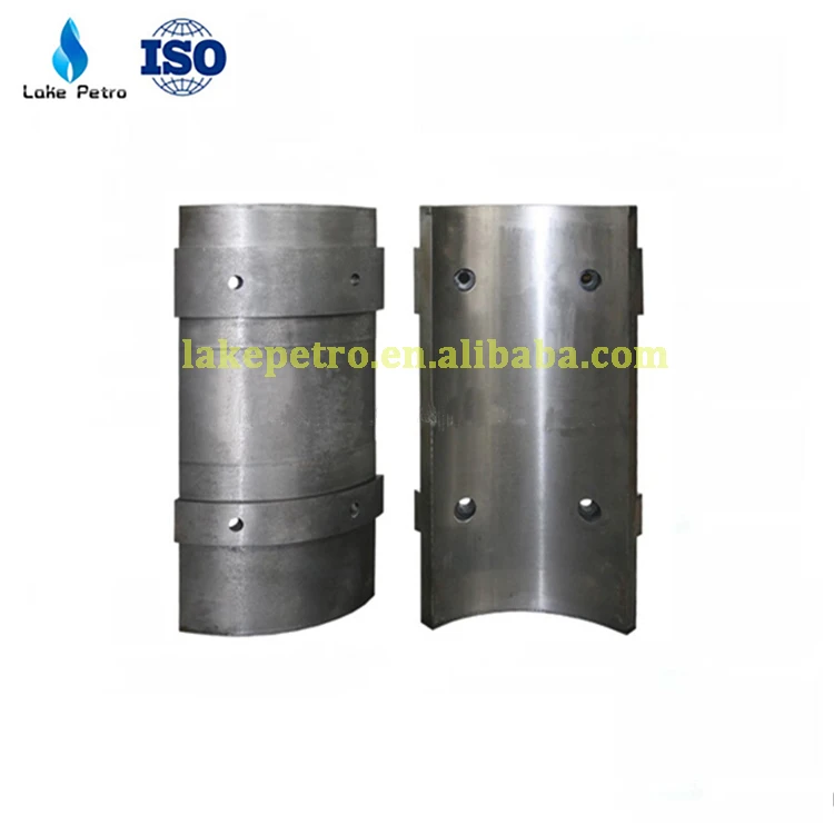
We now offer new crossheads and capsules for both EMSCO D-375 and DB-550 duplex pumps. You can also find slides and shoes for certain models. Available parts currently in our inventory include:

A mud pump (sometimes referred to as a mud drilling pump or drilling mud pump), is a reciprocating piston/plunger pump designed to circulate drilling fluid under high pressure (up to 7,500 psi or 52,000 kPa) down the drill string and back up the annulus. A mud pump is an important part of the equipment used for oil well drilling and manufactured according to API specification 7K.
The advantages of the drilling mud pump include the ability to move high-solids-content fluids laden with abrasives, the ability to pump large particles, ease of operation and maintenance, reliability, and the ability to operate over a wide range of pressures and flow rates by changing the diameter of pump liners and pistons.
As an important equipment for oilfield drilling operation, a drilling mud pump delivers circulating high-pressure drilling fluid or drilling mud to the bottom of the oil well, flushes the bottom of the well, breaks the rock, cools, lubricates and clean the drill bit, and carries the cuttings back to the ground.
The drilling mud is also used to suspend and carry out drill cuttings from the drill bits as it is brought in and out of the hole. This ensures that the drill bit does not clog and overheat, and makes the entire drilling operation smooth and safe.
Rotational power is supplied to the mud pump through an external power source like a diesel engine or electric motor. The power end of the mud pump converts the rotational energy through a crankshaft to a reciprocating motion of pistons.
The pistons move back and forth in mud pump liners, exerting a force on the cylinder chamber. During the retraction of the piston, valves open to allow the fluid to be drawn into the cylinder. Once the piston has fully retracted, it is pushed back into the cylinder.

A properly serviced pulsation dampener is critical for your mud pumps’ efficiency, safety, and performance. Unfortunately, there aren’t many resources available to educate personnel on executing safe and effective servicing procedures. Please review the following steps with your personnel for safe pulsation dampener maintenance.

When choosing a size and type of mud pump for your drilling project, there are several factors to consider. These would include not only cost and size of pump that best fits your drilling rig, but also the diameter, depth and hole conditions you are drilling through. I know that this sounds like a lot to consider, but if you are set up the right way before the job starts, you will thank me later.
Recommended practice is to maintain a minimum of 100 to 150 feet per minute of uphole velocity for drill cuttings. Larger diameter wells for irrigation, agriculture or municipalities may violate this rule, because it may not be economically feasible to pump this much mud for the job. Uphole velocity is determined by the flow rate of the mud system, diameter of the borehole and the diameter of the drill pipe. There are many tools, including handbooks, rule of thumb, slide rule calculators and now apps on your handheld device, to calculate velocity. It is always good to remember the time it takes to get the cuttings off the bottom of the well. If you are drilling at 200 feet, then a 100-foot-per-minute velocity means that it would take two minutes to get the cuttings out of the hole. This is always a good reminder of what you are drilling through and how long ago it was that you drilled it. Ground conditions and rock formations are ever changing as you go deeper. Wouldn’t it be nice if they all remained the same?
Centrifugal-style mud pumps are very popular in our industry due to their size and weight, as well as flow rate capacity for an affordable price. There are many models and brands out there, and most of them are very good value. How does a centrifugal mud pump work? The rotation of the impeller accelerates the fluid into the volute or diffuser chamber. The added energy from the acceleration increases the velocity and pressure of the fluid. These pumps are known to be very inefficient. This means that it takes more energy to increase the flow and pressure of the fluid when compared to a piston-style pump. However, you have a significant advantage in flow rates from a centrifugal pump versus a piston pump. If you are drilling deeper wells with heavier cuttings, you will be forced at some point to use a piston-style mud pump. They have much higher efficiencies in transferring the input energy into flow and pressure, therefore resulting in much higher pressure capabilities.
Piston-style mud pumps utilize a piston or plunger that travels back and forth in a chamber known as a cylinder. These pumps are also called “positive displacement” pumps because they literally push the fluid forward. This fluid builds up pressure and forces a spring-loaded valve to open and allow the fluid to escape into the discharge piping of the pump and then down the borehole. Since the expansion process is much smaller (almost insignificant) compared to a centrifugal pump, there is much lower energy loss. Plunger-style pumps can develop upwards of 15,000 psi for well treatments and hydraulic fracturing. Centrifugal pumps, in comparison, usually operate below 300 psi. If you are comparing most drilling pumps, centrifugal pumps operate from 60 to 125 psi and piston pumps operate around 150 to 300 psi. There are many exceptions and special applications for drilling, but these numbers should cover 80 percent of all equipment operating out there.
The restriction of putting a piston-style mud pump onto drilling rigs has always been the physical size and weight to provide adequate flow and pressure to your drilling fluid. Because of this, the industry needed a new solution to this age-old issue.
As the senior design engineer for Ingersoll-Rand’s Deephole Drilling Business Unit, I had the distinct pleasure of working with him and incorporating his Centerline Mud Pump into our drilling rig platforms.
In the late ’90s — and perhaps even earlier — Ingersoll-Rand had tried several times to develop a hydraulic-driven mud pump that would last an acceptable life- and duty-cycle for a well drilling contractor. With all of our resources and design wisdom, we were unable to solve this problem. Not only did Miller provide a solution, thus saving the size and weight of a typical gear-driven mud pump, he also provided a new offering — a mono-cylinder mud pump. This double-acting piston pump provided as much mud flow and pressure as a standard 5 X 6 duplex pump with incredible size and weight savings.
The true innovation was providing the well driller a solution for their mud pump requirements that was the right size and weight to integrate into both existing and new drilling rigs. Regardless of drill rig manufacturer and hydraulic system design, Centerline has provided a mud pump integration on hundreds of customer’s drilling rigs. Both mono-cylinder and duplex-cylinder pumps can fit nicely on the deck, across the frame or even be configured for under-deck mounting. This would not be possible with conventional mud pump designs.
The second generation design for the Centerline Mud Pump is expected later this year, and I believe it will be a true game changer for this industry. It also will open up the application to many other industries that require a heavier-duty cycle for a piston pump application.
This application claims priority from U.S. Patent Application No. 61/345,858, entitled “Mud Pump” and filed on May 18, 2010, in the name of Gerald Lesko; which is hereby incorporated by reference for all purposes.
It is known to use pumps to provide drilling mud under pressure in the drilling of wells. Pressurized drilling mud is delivered down a hollow drill string as the well is being drilled to carry away cuttings up the annulus surrounding the drill string to ground level. Such drilling operations are well known to those skilled in the art.
Prior art pumps can use a motor to turn a crankshaft or “pump shaft” to convert rotary motion to a reciprocating motion. The pump shaft moves a connecting rod coupled to a crosshead that moves within a fixed crosshead slide to provide this conversion. The crosshead is coupled to a “pony rod” that, in turn, is coupled to a piston rod that provides the pumping motion in a pump module, as well known to those skilled in the art.
The above-mentioned mechanical arrangement can be multiplied so that a multitude or plurality of pump modules can be operated from a single pump shaft. The outputs of each pump module can be coupled to a common manifold from which pressurized drilling mud can be provided to the drill string. By coupling the pump module outputs to a common manifold, the pulsing of the pressure of the drilling mud can be reduced or smoothed out, this being a problem well known to those skilled in the art. The disadvantage of this mechanical arrangement is the size and complexity of the components involved to provide a multi-module pump.
It is also known in the oil and gas industry to drill horizontal wells. These are wells that are initially drilled vertically and, with the use of directional drilling equipment as well known to those skilled in the art, the direction of drilled well becomes horizontal or parallel with the ground surface. It is known to drill horizontal wells 5000 to 7500 feet in length or more. To do so requires the use of “mud motors”, motors that are powered by the delivery of highly pressurized drilling mud pumped through the drill string so as to enable the turning of the drill bit. It is also known that to drill such wells, drilling operators will use at least two or more conventional mud pumps powered by 1000 horsepower or more motors. Each mud pump is housed in its own pump house and occupies space at the drilling site. As each additional pump house increases the number of structures at a drilling site, the number of truckloads required to deliver the necessary equipment to a drilling site also increases. All this additional equipment and number of truckloads to deliver the equipment add cost to the drilling of the well.
It is, therefore, desirable to provide a pump that can convert rotary motion to reciprocating motion without having to use connecting rods, crossheads, crosshead slides and pony rods to reduce its size, complexity and cost to manufacture. It is also desirable to provide a mud pump that is compact in size but can deliver pressurized mud at a volume equivalent to two or more conventional mud pumps.
A pump is provided that comprises a pump shaft having at least one eccentric lobe that is substantially circular. A motor is used to provide the rotational power to the pump shaft. In one embodiment, the motor can be coupled directly to the pump shaft. In another embodiment, a transmission can be used between the motor and the pump shaft to reduce the angular speed of the rotational power provided to the pump shaft. In a representative embodiment, a one or two-stage gear transmission can be used. In a further embodiment, the motor can be a 3-phase AC motor controlled by a variable frequency drive mechanism to control the speed of the motor.
In one embodiment of the pump, the eccentric lobe can be rotatably disposed within a connecting rod having a substantially circular opening to receive the lobe at one end with the other end rotatably pinned to a slide configured to move in a horizontal and linear manner. In one embodiment, the slide can be slidably disposed within a pair of slide support plates that constrains the slide to move in a linearly and horizontal or side-to-side manner. In one embodiment, slide-bearing mechanisms can be disposed between the slide and the support plates so that the slide can move side-to-side with minimal friction. In a representative embodiment, the slide-bearing mechanism can further comprise means for adjusting a loading force on the slide-bearing mechanism against the slide so that the slide is further constrained to horizontal and linear movement.
As the lobe rotates within the connecting rod opening, the connecting rod slide can move up and down thereby moving the slide linearly and horizontally between the slide support plates. As the slide frame moves side to side, it can move a piston rod in and out to operate a pump module. By virtue of this configuration, the slide can have a piston rod operatively coupled to one or both opposing sides of the slide. Therefore, a single slide can operate one or two pump modules at the same time. In a further embodiment, the pump shaft can comprise a plurality of eccentric lobes thereby allowing a plurality of slides to be operated by the lobes and, hence, a plurality of pump modules to be operated from a single rotating pump shaft.
Broadly stated, in some embodiments, a mud pump is provided, comprising: a frame; at least one pump module disposed on the frame, the at least one pump module comprising an inlet port and an outlet port; a pump shaft rotatably disposed in the frame for receiving rotational power from a motor, the pump shaft having at least one substantially circular eccentric lobe disposed thereon, the centre of the at least one eccentric lobe displaced or offset from the longitudinal axis of the pump shaft; at least one slide disposed in the frame, the at least one slide operatively configured to move linearly side-to-side within the frame; at least one piston rod assembly operatively coupling the at least one slide to the at least one pump module; and a connecting rod comprising first and second ends operating coupling the pump shaft to the at least one slide, the first end rotatably disposed on the at least one eccentric lobe, the second end rotatably pinned to the at least one slide whereby rotation of the pump shaft causes the slide to move side-to-side that, in turn, causes the at least one piston rod assembly to operate the at least one pump module.
Broadly stated, in some embodiments, a mud pump is provided, comprising: a platform; a lattice frame disposed on the platform; at least one pump module disposed on the frame, the at least one pump module comprising an inlet port and an outlet port; a pump shaft rotatably disposed in the frame for receiving rotational power from a motor, the pump shaft having at least one substantially circular eccentric lobe disposed thereon, the centre of the at least one eccentric lobe displaced or offset from the longitudinal axis of the pump shaft; a motor operatively coupled to the pump shaft, the motor disposed on the platform; at least one slide disposed in the frame, the at least one slide operatively configured to move linearly side-to-side within the frame; at least one piston rod assembly operatively coupling the at least one slide to the at least one pump module; and a connecting rod comprising first and second ends operating coupling the pump shaft to the at least one slide, the first end rotatably disposed on the at least one eccentric lobe, the second end rotatably pinned to the at least one slide whereby rotation of the pump shaft causes the slide to move side-to-side that, in turn, causes the at least one piston rod assembly to operate the at least one pump module.
FIG. 7 is a perspective view depicting the frame of the mud pump of FIG. 1 showing only the slides, the slide bearings, the slide bearing support plates and the piston assemblies;
Referring to FIGS. 1 to 13, one embodiment of a mud pump is illustrated. In this embodiment, mud pump 10 can comprise lattice frame 18 and pump modules 24 mounted thereon. Frame 18 can further comprise mounting tabs 14 for attaching mud pump 10 to a platform, to a skid or to a pump house.
For the purposes of this specification, and as shown specifically in the figures, each pump module 24 can comprise inlet port 25, outlet port 35, top access port 37 and side access port 36. Pump module 24, as illustrated, can be any suitable pump module that is readily available to the mud pump industry and is well known to those skilled in the art. As shown in FIG. 1, pump module 24 is shown as a singular device having three pump units disposed therein. It is obvious to those skilled in the art that pump module 24 can comprise one or more pump units use in combination. Representative examples of pump module 24 are pump modules having an 800 horsepower rating as manufactured by Continental Emsco in the U.S.A. or their equivalent. Such pumps have interchangeable liners of different diameters whereby the volume of mud handled by a pump module per pump cycle can be adjusted upwards or downwards depending on the diameter of the liner. Generally speaking, the smaller the volume per pump module, the greater the pressure the mud can be pumped at.
Referring to FIG. 1, mud pump 10 is shown having cover 20 disposed on top of lattice frame 18. Input shaft 12 can be connected to a motor (not shown) to provide rotational input power to mud pump 10. In some embodiments, an internal combustion motor can be used to provide rotational input power to mud pump 10. In other embodiments, an electric motor of suitable power rating can be used. In further embodiments, a variable frequency drive mechanism (not shown) as well known to those skilled in the art can be used to control the electrical power provided to the electric motor thereby controlling the rotational speed the motor operates at to supply rotational input power to mud pump 10.
In one embodiment, mud pump 10 can comprise transmission 22 to couple shaft 12 to the operating components of mud pump 10. Transmission 22 can be a single-stage or dual-stage gear transmission to reduce the rotational speed of input shaft 12 to the required rotational speed for proper operation of pump shaft 30 rotatably disposed in mud pump 10. In other embodiments, transmission 22 can comprise a planetary gear transmission. In further embodiments, transmission 22 can comprise helical gears. In yet other embodiments, transmission 22 can comprise spur gears. Intake manifold 52, comprising inlet 54, is shown attached to pump module inlet ports 25. Outlet manifold 58, comprising couplers 62 and end caps 66, is shown attached to pump module outlet ports 35. In one embodiment, frame 18 can comprise return lines 68 that provide communication from galleys 38 to reservoir 70. When in operation, lubricating oils are used to lubricate the moving components of mud pump 10. These oils will collect in galleys 38 and return to reservoir 70 through return lines 68 to be re-circulated through mud pump 10.
Referring to FIG. 2, a rear elevation view of mud pump 10 is shown. In this figure, piston rod support bushings 31 are shown disposed on sidewalls 19 of frame 18. Piston liners 26 are shown disposed between pump modules 24 and support bushings 31. Couplers 41 can be used to couple liners 26 to support bushings 31. As noted above, liners 26 can be comprised of various diameters depending on the volume and the pressure drilling mud is to be produced by mud pump 10.
Referring to FIGS. 3 and 4, front views of mud pump 10 are shown. In this embodiment, pump modules 24 are shown with outlet ports 35 exposed having no output manifold attached thereon to show valve mechanism 39 disposed therein. In one embodiment, pump module 24 can comprise “sucker-cup” pump mechanisms as well known to those skilled in the art. In the illustrated embodiment, an output manifold (not shown) can be attached to the shown outlet ports 35 to collect drilling mud pumped by pump module 24, in addition to outlet manifold 58 shown in FIGS. 1 and 2, or it can be capped with a cover (not shown). Input ports 25 can be coupled together with intake manifold 52 that directs drilling mud into pump modules 24. In one embodiment, coolant pump 34 can be used to circulate coolant through piston liners 26 and oil pump 32 can be used to pump lubricating oil through support bushings 31 to lubricate the moving components therein, as described in more detail below and as shown in FIG. 13.
Referring to FIGS. 5 and 6, front cross-section views of mud pump 10 are shown revealing the internal components of the embodiment shown therein. In this embodiment, pump shaft 30 rotates as a result of input rotational power applied to input shaft 12 that is operatively coupled to pump shaft 30 via transmission 22 as shown in FIG. 4. In one embodiment, pump shaft 30 can comprise eccentric 80 disposed thereon and affixed thereto with pin 82. Rotatably disposed on eccentric 80 is connecting rod 84. In another embodiment, eccentric bearing 83 is disposed between eccentric 80 and connecting rod 84. In a further embodiment, connecting rod 84 is rotatably pinned to sidewall 28 b(and sidewall 28 aas shown in FIGS. 8 and 9) of slide 28 via pin 86. In yet another embodiment, bearing 85 can be disposed between pin 86 and connecting rod 84. In FIG. 5, eccentric 80 is shown rotating clockwise thereby moving connecting rod 84 upwards and to the right in this figure. In so doing, slide 28 is being pushed to the right. In one embodiment, slide 28 is disposed between upper support plate 44 and lower support plate 46 to help keep slide 28 moving in a horizontal linear path, and to resist the bending moment caused by the rotation of pump shaft 30 and eccentric 80. In another embodiment, upper slide bearing 43 can be disposed between upper plate 44 and slide 28, and lower slide bearing 45 can be disposed between lower plate 46 and slide 28 as a means to reduce the friction between slide 28 and upper and lower plates 44 and 46 as slide 28 moves side-to-side.
As slide 28 moves to the right, it pushes piston rod 27 aand, hence, piston 40 ato the right in liner 26 ato push fluids in pump chamber 42 aout through valve 39 aoto outlet ports 35 (not shown) and outlet manifold 58 (not shown). In so doing, piston rod 27 balso pulls piston 40 bin liner 26 bto the right thereby drawing in fluid through valve 39 bifrom intake manifold 52.
In FIG. 6, eccentric 80 is shown rotated further clockwise (from FIG. 5) thereby moving connecting rod 84 downward and to the left. In so doing, piston 40 ais being pulled to the left thereby drawing in fluid into pump chamber 42 athrough valve 39 aifrom intake manifold 52 while piston 40 bis pushed to the left thereby pushing fluid out of pump chamber 42 bthrough valve 39 boto outlet ports 35 (not shown) and outlet manifold 58 (not shown). In this figure, the connecting rods 84 of two adjacent stages rising above the top of frame 18.
Referring to FIG. 7, mud pump 10 is shown without pump modules 24, cover 22, piston liners 26, pump shaft 30, slides 28 and connecting rods 84. In this illustrated embodiment, frame sidewalls 19 are visible as are removable caps 17, which are configured hold pump shaft 30 in place in frame 18. Also visible are piston rods 27, rod support bushings 31, couplers 41 and pistons 40. In one embodiment, mud pump 10 can comprise means for applying a loading force to upper support plates 44 to keep slide 28 confined to a horizontally linear range of motions. In some embodiments, these means can comprise a plurality of setscrew rails 48 disposed on frame 18 near sidewalls 19 and disposed on caps 17. In further embodiments, setscrew rails 48 can comprise a plurality of setscrews 47 threadably attached to and through said setscrew rails. Setscrews 47 can be tightened to apply forces to various locations on upper support plates 44 whereby the loading force applied to upper support plates can be adjusted at each location of setscrews 47 to ensure that slide 28 is constrained to horizontal linear movement. While the illustrated embodiment shows setscrews 47 as being manually adjustable for applying force to slide 28, it is obvious to those skilled in the art that mud pump 10 can comprise further means for monitoring the movement of slides 28 and for automatically adjusting setscrews 47 with electro-mechanical servo motors, or the like, so that setscrews 47 are dynamically adjusted in real-time to ensure that proper force is being applied to slide 28 at all times to keep its movement linearly horizontal.
Referring to FIG. 8, the mud pump 10 of FIG. 7 is now shown with frame 18 removed to reveal slides 28. In some embodiments, each slide 28 can comprise a pair of substantially parallel spaced-apart sidewalls 28 aand 28 b, as shown in FIGS. 8, 9 and 10. In this embodiment, slides 28 can comprise openings 29 disposed through sidewalls 28 aand 28 bfor pump shaft 30 (not shown) to pass through and pin openings 88 disposed through sidewalls 28 aand 28 bthat are configured to receive connecting rod pins 86 (not shown). In some embodiments, mud pump 10 can further comprise one or more eccentric rods 49 disposed beneath lower support plates 46 for applying upwards force thereto for ensuring that slide 28 is constrained to horizontal linear movement. This is also shown in FIGS. 9, 10, 11 and 12. In some embodiments, eccentric rods 49 can be rotated or adjusted and then set into position by turning rod adjusters 50. While the illustrated embodiment shows eccentric rods 49 as being manually adjustable for applying force to slide 28, it is obvious to those skilled in the art that mud pump 10 can comprise further means for monitoring the movement of slides 28 and for automatically adjusting eccentric rods 49 with electro-mechanical servo motors, or the like, operatively coupled to rod adjusters 50 so that eccentric rods 49 are dynamically adjusted in real-time to ensure that proper force is being applied to slide 28 at all times to keep its movement linearly horizontal.
Referring to FIG. 13, a cross-section view is shown of the internal pumping mechanism of mud pump 10. In some embodiments, piston rod 27 can be coupled to slide 28 by threading piston rod 27 into threaded opening 91 disposed on slide 28. In other embodiments, piston rod 27 can be further secured with lock nut 101 threaded on piston rod 27 and tightened against slide 28. In yet further embodiments, piston rod stud 92 can be disposed in an opening disposed through piston rod 27 and secured to slide 28 in threaded opening 93. In some embodiments, piston rod stud 92 can further comprise flange 95 that can rest against shoulder 94 disposed within piston rod 27. Piston rod stud 92 can also serve as means for mounting piston 40 and piston retaining caps 96 and 97 thereon. Nut 98 can be used to secure piston 40 and caps 96 and 97 on piston rod stud 92.
In some embodiments, mud pump 10 can comprise means for circulating coolant in piston liner 26 behind piston 40 to prevent overheating of the mechanism when in operation. As shown in FIG. 13, coolant can be pumped by coolant pump 34 (as shown in FIG. 4) into liner chamber 106 through coolant inlet 102 via lines, hoses or piping (not shown). Coolant can the flow through, and circulate within, chamber 106 and then exit through coolant outlet 104. Lines, hoses and piping (not shown) can be coupled to outlet 104 so that the heated coolant can be collected, cooled and re-circulated. In other embodiments, inlet 102 and outlet 104 can further comprise one-way valves, such as ball-valves as one example obvious to those skilled in the art, such that coolant can be drawn into chamber 106 through inlet 102 as piston 40 is moving towards pump module 24 (not shown), and then expelled from chamber 106 through outlet 104 and piston 40 is moving away from pump module 24.
In some embodiments, mud pump 10 can comprise means for circulating lubricating oil to piston rod 27 as it reciprocates back and forth through support bushing 31. As shown in FIG. 13, lubricating oil can be pumped by oil pump 32 (as shown in FIG. 4) into oil inlet 108 where it can flow into annulus 110 between piston rod 27 and support bushing 31 thereby maintaining a layer of lubricating oil therebetween. Oil can then flow out of annulus 110 into galleys 38 (as shown in FIG. 1) where the oil can be collected and re-circulated. In other embodiments, barrier seals 99 and ice-breaker wear band 100 can be disposed between piston rod 27 and support bushing 31 as sealing means to separate and isolate chamber 106 from annulus 110 so that coolant does not intermingle with and contaminate the lubricating oil, and vice-versa.
In the embodiments illustrated the figures herein, there are three slides 28 shown, each coupled to two pump modules 24 thereby resulting in the operation of six pump modules. It is obvious to those skilled in the art that fewer or more slides mechanisms can be implemented to either decrease or increase the number of pump modules that can be operated. It is also obvious to those skilled in the art that a slide frame can be releasably coupled to a single piston rod to, therefore, operate a single pump module.
Referring to FIG. 6, pump shaft 30 is shown turning three connecting rods 84. This necessarily requires pump shaft 30 having three eccentric lobes 80. In this configuration, the lobes can be displaced nominally 120° apart from each other such that the lobes can be substantially spaced equally apart around the circumference of pump shaft 30. In embodiments where pump shaft 30 comprises two eccentric lobes 80, the lobes can be displaced nominally 180° apart. In other embodiments where pump shaft 30 comprises two lobes 80, one lobe 80 can be displaced 178° from the other lobe 80 so that pump shaft 30 can more easily turn from a dead stop. In other embodiments where additional eccentric lobes are disposed on pump shaft 30, the lobes can be substantially spaced equally apart on pump shaft 30. For example, for a four-lobe shaft, each lobe 80 can be displaced 90° nominally from each other lobe 80. If five lobes are disposed on pump shaft 30, the lobes can be displaced nominally 72° apart on pump shaft 30. For six lobes disposed on pump shaft 30, the lobes can be displaced nominally 60° apart, and so on.
In operation, mud can be supplied to inlet 54 on intake manifold 52 from an external pump (not shown) drawing mud from a mud tank (not shown) as well known to those skilled in the art. As slides 28 operate pump modules 24, mud is drawn into pump modules 24 from intake manifold 52 and pumped out of pump modules 24 into outlet manifold 58 via outlet manifold couplers 62 disposed between pump modules 24 and outlet manifold 58. The pumped mud can exit outlet manifold 58 via outlet 60 that can be connected to a mud delivery pipe and/or hose for use on a drilling rig (not shown) as well known to those skilled in the art. In one embodiment, the diameter of inlet 54 and the pipe that make up intake manifold 52 can be nominally ten inches whereas the diameter of outlet and the pipe that make up outlet manifold 58 can be nominally four inches. In another embodiment, outlet manifold 58 can comprise couplings (not shown) for connection with a pressure gauge to provide a visual indication of the pressure of the mud being pumped and/or a pressure relief valve to provide means to limit the pressure of the mud being pumped by mud pump 50. It is obvious to those skilled in the art that the diameters of inlet 54, intake manifold 52, outlet manifold 58 or outlet 60 can be increased or decreased depending on the volume and pressure of drilling mud required in the drilling of a well.
In operation, it is expected that mud pump 10 can operate up to 65 revolutions per minute using a 1000 horsepower motor, which translates up to 130 pump module strokes per minute per slide frame mechanism given that each slide frame can be coupled to two pump modules. It is also anticipated that mud pump 10 can pump up to 800 gallons or 4 cubic meters of drilling mud per minute. Using 7-inch liners in the pump modules, it is expected that mud pump 10 can pump mud up to 1500 pounds per square inch in pressure. It is also expected that mud pump 10 would weigh approximately 45,000 pounds and deliver the equivalent volume and pressure of drilling mud as a conventional mud pump powered by a 1600 horsepower motor weighing up to 120,000 pounds.
Referring to FIG. 14, mud pump 10 is shown positioned in pump house 56, a structure used to house mud pumps at drilling sites. Access to mud pump 10 is done through doorways 64. In this configuration, mud pump 10, with electric motor 87 coupled to mud pump 10 via transmission 22, is positioned “lengthwise” in pump house 56. Referring to FIG. 15, the combination of mud pump 10 and motor 87 is shown in pump house 56 rotated 90 degrees. The compactness of mud pump 10 can allow it to be installed in this manner in pump house 56 whereby access to the inlet and outlet to mud pump 10 is through doorway 64. In addition, more than one mud pump 10 can be installed in pump house 56 thereby reducing the number of pump houses required at a drilling site if the well being drilled requires a volume of pressurized drilling mud greater than what one mud pump 50 can provide.

Note: To break in new pump, run sprayer dry for no longer than two minutes. Replace hose when mud seeps through slots in the base and leaves material on the floor.

Editor"s Note: This is the second of five parts of our feature, The History of Pumps. This timeline was developed through research, credible sources and the knowledge of friends in the industry, The history of pumps is long and illustrious. This account represents highlights of some of the major historical and technological developments. We welcome your contributions.
200 BC Greek inventor and mathematician Ctesibius invents the water organ, an air pump with valves on the bottom, a tank of water in between them and a row of pipes on top. This is the principal design that is now known as the reciprocating pump.
200 BC Archimedean screw pump is designed by Archimedes is considered one of the greatest inventions of all time and is still in use today for pumping liquids and granulated solids in both the industrialized world and in the third world—where it is a preferred way to irrigate agricultural fields without electrical pumps.
1475 According to Reti, the Brazilian soldier and historian of science, the first machine that could be characterized as a centrifugal pump was a mud lifting machine that appeared in a treatise by the Italian Renaissance engineer Francesco di Giorgio Martini.
1588 Sliding vane water pump technology is described by Italian engineer Agostino Ramelli in his book “The Diverse and Artifactitious Machines of Captain Agostino Ramelli,” which also included other pump and engine designs.
1636 Pappenheim, a German engineer, invents the double deep-toothed rotary gear pump, which is still used to lubricate engines. This gear pump made it possible to dispense with the reciprocating slide valves used by Ramelli. Pappenheim drove his machine by an overshot water wheel set in motion by a stream and was used to feed water fountains. The emperor Ferdinand II granted him a “privilege” - the equivalent of a patent - in respect of this invention.
1675 Sir Samuel Moreland—an English academic, diplomat, spy, inventor and mathematician—patents the packed plunger pump, capable of raising great quantities of water with far less proportion of strength than a chain or other pump. The piston had a leather seal. Moreland"s pump may have been the first use of a piston rod and stuffing box (packed in a cylinder) to displace water.
1790 Briton Thomas Simpson harnesses steam power to pumping engines for municipal water applications and founds the London company Simpson and Thompson Co. (predecessor to Worthington Simpson).
1845 Henry R. Worthington invents the first direct-acting steam pumping engine. Worthington Pump designed its first products to power canal boats and U.S. naval vessels. Worthington later pioneered pump designs for boiler feed, oil pipeline and hydro-electric applications.
1851 John Gwynne files his first centrifugal pump patent. His early pumps were used primarily for land drainage, and many can still be seen today in pump house museums. They were usually powered by Gwynnes" steam engines. By the end of the 19th century, Gwynne was producing pumps of all sizes to cover all industrial applications, from small electric pumps to those rated at 1,000 tons per minute. His company had also begun to produce scientific pumps, e.g., porcelain pumps for chemical works. In the 1930s they were producing almost 1,000 different models.
1860 Adam Cameron founds the Cameron Steam Pump Works, and becomes another pioneer in reciprocating steam pump engines. Like Worthington, Cameron"s first products were used to power merchant marine and U.S. naval vessels. Cameron pumps were later applied in water resources, oil pipeline and refining and boiler feed.
1886 Jens Nielsen, founder of Viking Pump Company, invents the internal gear pumping principal while designing a pump to remove excess water that was seeping into his limestone quarry from a nearby creek.
1886 United Centrifugal Pumps is incorporated. It becomes the world"s foremost supplier of high-pressure crude oil and refined product pipeline pumps.
1899 Robert Blackmer invents rotary vane pump technology, a pump design that was an important departure from the old gear principle and predecessor to today"s sliding vane pumps.
1902 Aldrich Pump Company begins manufacturing the world"s first line of reciprocating positive displacement pumps for steel mills and mine dewatering.
1908 Hayward Tyler creates its first electric motor for use under water and develops the wet stator motor for use as a boiler circulation glandless motor-pump.
1911 Jens Nielsen builds the first internal gear pump, founding the Viking Pump Company. The Viking Rotary “Gear-Within-A-Gear” pump (the first of its kind) is placed on the market.
1912 Durion, a universally corrosion-resistant material, is invented by the Duriron Castings Company (later known as Durco Pump) and is applied to process equipment.
1915 Albert Baldwin Wood invents the Wood trash pump. Wood spearheads the reclamation from swamp and the efforts to develop much of the land now occupied by the city of New Orleans. Some of Wood"s pumps have been in continuous use for more than 80 years without need of repairs. New ones continue to be built from his designs.
1916 While Armais Sergeevich Arutunoff first invented submersible pumps in Russia in 1916, their use in the United States did not begin until the 1950s. Arutunoff first designed his pump for use in ships, water wells and mines. He altered the design to work in oil wells. Thanks to further refinements to Arutunoff"s design, there are more types of submersible pumps, allowing use in other applications such as pumping drinking water, creating fountains and pumping wastewater.
1921 Harry LaBour founds LaBour Pump Company. A pioneer in the development of pumps for the chemical industry, LaBour developed corrosion-resistant alloys to incorporate into his pumps. Until his time, sulfuric acid was always pumped with lead pumps, the only known material that could handle certain concentrations of the acid.
1921 Jeumont-Schneider begins manufacturing water and slurry pumps in Jeumont, France. It later develops solids-handling pumps and segmental ring section multistage pumps.
1924 Durco Pump introduces the world"s first pump specifically designed for chemical processing. It would go on to establish undisputed global leadership in ANSI pump design.
1926 O.H. Dorer receives a patent for the first inducer, which reduces the required NPSH. Inducers did not become incorporated into standard pump lines until the 1960s.
1929 Pleuger incorporates in Berlin, Germany. Its first offerings are submersible motor pumps for dewatering in the construction of underground railways and subways. Pleuger pioneers the first successful application of submersible motor pumps in offshore service.
1929 Stork Pompen produces the first concrete volute pump for drainage, integrating the pump housing in the civil construction of the pumping station.
1930 While inventing a compressor for jet engines, aviation pioneer René Moineau discovers that this principle could also work as a pumping system.The University of Paris awarded Moineau a doctorate of science for his thesis on “the new capsulism.” His pioneering dissertation laid the groundwork for the progressing cavity pump.
1933 The original version of the Bush Pump is designed as a closed-top cylinder pump. In 1960 the design was modernized. The base of the well was from then on bolted to the well casing and got its current name, The Zimbabwe Bush Pump, the National Standard for hand pumps in Zimbabwe. After Zimbabwe"s independence in 1980, the government creates its own modernized version of the pump, B-type Zimbabwe Bush Pump. The pump is today regarded as a national treasure. In 1997, it was pictured on a postal stamp.
1933 J.C. Gorman and Herb Rupp introduce a pump with a “non-clogging” feature. It outperforms any other self-priming centrifugal pump previously invented. The company Gorman-Rupp is established.
1936 Robert Sheen invents the metering pump. The core of his invention was a method of controlled volume that was inherent to the pump. The first pumps were assembled in the basement of his father, Milton Roy Sheen"s, home, where the initial patterns for castings were made.
1937-1939 Smith Precision Products Company (Smith Pumps) designs three pumps, two of which (models 300 and 200) were specifically designed for LP-gas transfer.
1939 Dorr-Oliver Pump Company develops the Oliver Diaphragm Slurry pump for slurry transfer. Originally designed for mining slurry transfer with their associated acids, it developed into a Primary Sludge Underflow Pump for the wastewater industry starting in the 1970s after the Clean Water Act.
1940 Reuben Smith, of Smith Precision Products Company (Smith Pumps), receives the first approval for an LP-gas pump from the California Industrial Accident Commission. This was for the model 4X pump and the approval was a "suitable for use" certificate.
1942 The Gorman-Rupp team creates the first commercially available solids-handling trash pump to respond to the contractor"s need for a pump to withstand the considerable rigors of pumping out trash-laden septic tanks, cesspools and outhouses.
1944 During World War II, Goulds extra-quiet trim pumps are installed in every U.S. Navy submarine. That year, 157 Goulds men went to war and 157 women took their places on the Goulds manufacturing floor. Goulds earned the prestigious Army-Navy “E” Award that year for outstanding production of war materials.
1947 Flygt"s Sixten Englesson, a master of engineering, develops a prototype for the first submersible drainage pump, which is later known as the “parrot cage,” or B-pump, used in mining for construction.
1948 Smith Precision Products Company receives the patent for the first mechanical seal supplied for liquefied gas transfer pumps. It was first put into production in 1947.
1950 Vanton develops the Flex-i-liner sealless self-priming rotary pump which handles corrosive, abrasive and viscous fluids as well as those that must be transferred free of product contamination.
1954 Smith Precision Products Company (Smith Pumps) begins working with the Underwriters Laboratories to develop their first Standard for liquefied gas pumps, UL-51, which is still in use today.
In 1955, Jim Wilden invented air-operated double-diaphragm pump technology. It had the right air valve and diaphragms needed and was tough and versatile enough to meet the stringent demands of the mining and heavy-construction industries. During the 1980s, Wilden introduced plastic AODD pumps that have the ability to stand up to the harsh operating conditions and corrosive media transferred throughout the global chemical market. Photo courtest of Wilden.
1960s New lines of industrial pumps are developed by Goulds Pumps, including large double suction pumps, higher pressure pumps and non-metallic pumps. In home water systems, the jet water system is improved and a complete line of submersible pumps is completed.
1965 Warren Rupp"s heavy-duty, diverse AODD pump is introduced to the industrial market to address the vigorous demands of the steel mills and other industrial market applications.
Below: Marvin and Kathryn Summerfield founded Cascade Pump Company in 1948. They are pictured here at an industry tradeshow in the early 1950s. Photo courtesy of Cascade Pump Company.
1968 The ownership of Stenberg-Flygt AB is transferred to the American multinational enterprise ITT (International Telephone & Telegraph Corporation). Prior to this transfer, Stenberg-Flygt AB, AB Flygts Pumpar and Flygt International AB are consolidated as a single company.
1980s Gorman-Rupp unveils the nutating pump, a special purpose small pump used in health care applications; additional energy-efficient, self-priming centrifugal pumps; a series of lightweight portable pumps and high-pressure pumps with the first digital-control panels.
1985 Sims manufactures the first structural composite pump, all Simsite Vertical Pit Pump. Sims later won the Innovative Product Award for these products in 1990.
In 1933, J.C. Gorman and Herb Rupp introduced a pump which had a "non-clogging" feature. Their competitors claimed the pump would not work in a savage public awareness campaign to discredit the new design, which resulted in about $100,00 worth of "free advertising." At least one customer was willing to try it. National Ice Company purchased the first pump, and the company Gorman-Rupp was established. Photo courtesy of Gorman-Rupp Company.
1994 Two new major products are introduced by Goulds Pumps, the Industrial Model 3298 Magnetic Drive Pump and the Water Technologies Model GS “Global Submersible.”
1994 Sims receives the honor of approval from the United States Navy for composite centrifugal pump intervals. Simsite was tested and qualified for centrifugal pump replacement parts and was the first composite to be certified.
1994 Baha Abulnaga invents the slurry and froth pump with a split vane impeller. The split impeller helps to reduce recirculation in slurry pumps by dividing the space between the main vanes without reducing the passageway at the narrowest point, which is the eye of the impeller. In froth pumps, it helps to break up air bubbles that form and tend to block the flow.
1995 Sims manufactures the largest structural composite pumps in the world - two Simsite vertical turbine pumps for Potomac Electric Power Company. They are 40 feet long and 3 feet in diameter.
2006 Sims manufactures the largest structural composite centrifugal impeller in the world. This huge impeller was installed in a cooling tower pump for Puerto Rican Electrical Power Company. It is 50 inches in diameter and consumes 2,000 horsepower.


 8613371530291