
mud pump suction line strainer made in china

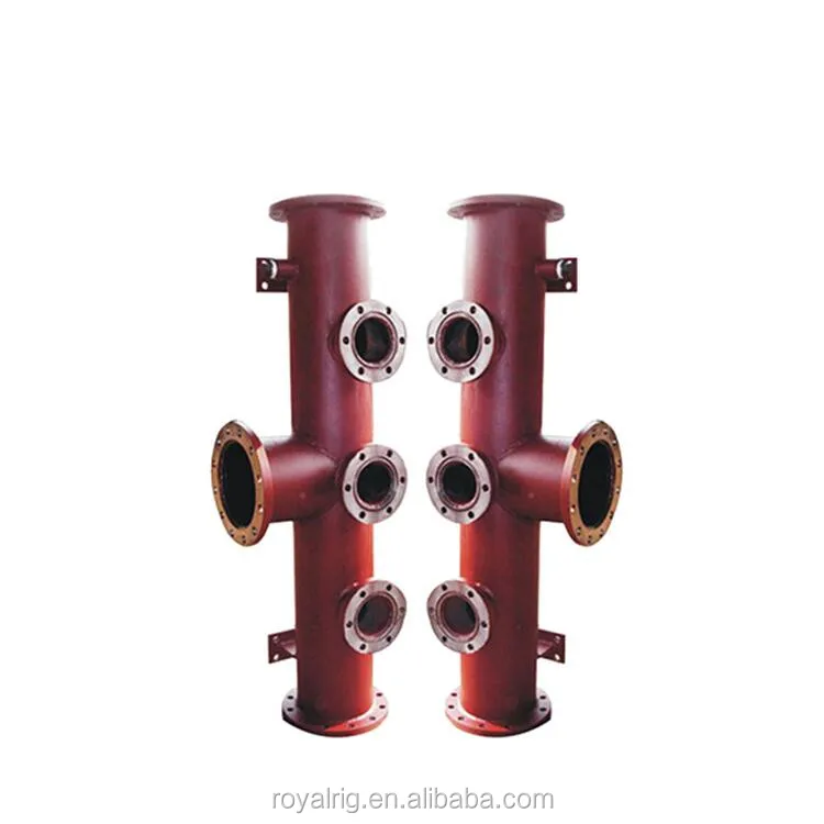
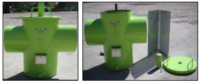
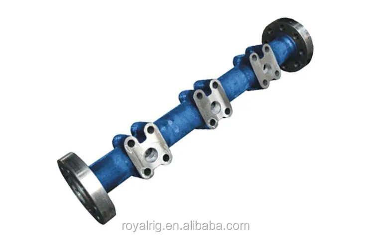
suction discharge and discharge manifold Description: The discharge line is the output end of pump, its end is provided with a discharge strainer assembly will mud pump generated pressure directly transported to underground; another end of the pipe with air out package assembly and safety valve and pressure gauge. It is the United States A487-9D material: cast iron, corrosion resistant and wide resistant temperature range and high strength. The finished product by hydrostatic pressure test, the test pressure 52MPa, no leakage defects Suction cover material for: ZG35CrMo PUMP TYPE DRAWING NO. ERP NO.

A wide variety of pump strainer mud pump options are available to you, such as 1 year, not available and 3 years.You can also choose from new, pump strainer mud pump,As well as from energy & mining, construction works , and manufacturing plant. And whether pump strainer mud pump is 1.5 years, unavailable, or {3}.

This website is using a security service to protect itself from online attacks. The action you just performed triggered the security solution. There are several actions that could trigger this block including submitting a certain word or phrase, a SQL command or malformed data.
This website is using a security service to protect itself from online attacks. The action you just performed triggered the security solution. There are several actions that could trigger this block including submitting a certain word or phrase, a SQL command or malformed data.

The Made-in-China F series mud pumps have same reliable quality and performance as other USA products. Now, F series mud pumps (from F-500 to F-2200) have been produced in batches and sold to many abroad oilfields. Your order for F series mud pumps is cordially welcome.
Huaxin"s export-orientated mud pump parts, including liners, pistons, piston inserts, valve inserts, oil seals, rod packing, fluid ends etc. All of them meet or exceed DIN and API standards and have been exported to U.K., Germany, USA, Canada, Pakistan, Middle East, and so on.

Drilling consumables such as mud pump systems and their components can drastically increase your uptime while reducing costs and health/safety/environmental (HSE) risks. To support your drilling needs, Forum’s patented P-Quip® mud pump system offers a single-source solution that integrates high-quality fluid end components for maximum longevity and performance.
With more than 20 years of successful operation in severe environments, P-Quip offers a proven track record for the lowest cost of ownership in the industry. As part of our commitment to quality, our mud pump parts use patented Banded Bore™ technology that significantly reduces stress concentrations and leads to longer module life.
One of Forum’s most committed core values is that “no one gets hurt,” and the P-Quip system is designed to support that principle. Streamlined and easy to use, it reduces or eliminates the need for manual force during maintenance, shrinking the time needed to replace high-use components and minimizing safety risks.
This website is using a security service to protect itself from online attacks. The action you just performed triggered the security solution. There are several actions that could trigger this block including submitting a certain word or phrase, a SQL command or malformed data.

The structural features and properties of F series mud pumps are more advanced. Wearing parts of fluid end can be universally used with those of API standards.
F series mud pumps are firm and compact in structure and small in size, with good functional performances, which can adapt to drilling technological requirements such as oilfield high pump pressure and large displacement etc. The F series mud pumps can be maintained at lower stroke rate for their long stroke, which effectively improves the feeding water performance of mud pumps and prolongs the service life of the fluid end. The suction stabilizer, with advanced structure and reliable service, can achieve the best buffering effect. Power ends of the F series mud pumps adopt the reliable combination of forced lubrication and splash lubrication to increase the service life of power ends.
This series of pumps is manufactured strictly in accordance with API Spec 7K Drilling and Workover Equipment Specifications and carried out delivery test in accordance with the standard.

A pump is a machine that transports fluid or pressurizes the fluid. It transmits the mechanical energy of the prime mover or other external energy to the liquid, so as to increase the energy of the liquid. The pump is mainly used to transport water, oil, acid-base liquid, emulsion, suspended emulsion, liquid metal and other liquids, as well as liquid, gas mixture and liquid containing suspended solids. Pumps can generally be divided into positive displacement pumps and power pumps according to their working principlesType pumps and other types of pumps. In addition to the classification according to the working principle, they can also be classified and named according to other methods. For example, according to the driving method, they can be divided into electric pumps and water turbine pumps; according to the structure, they can be divided into single-stage pumps and multi-stage pumps; according to the use, they can be divided into boiler feed pumps and metering pumps; according to the nature of the liquid delivered, they can be divided into pumps, oil pumps and mud pumps; according to the structure with or without shaft, they can be divided intoLinear pump, and traditional pump. The pump can only transport the material flow with fluid as the medium, and cannot transport solids.
The impeller is installed in the pump housing and fastened to the pump shaft. The pump shaft is directly driven by the motor. In the center of the pump housing, there is a liquid suction connected to the suction pipe. The liquid enters the pump through the bottom valve and the suction pipe. The liquid outlet on the pump housing is connected to the discharge pipe.
Before the pump is started, the pump casing is filled with the delivered liquid; after the pump is started, the impeller is driven by the shaft to rotate at a high speed, and the liquid between the blades must also rotate with it. Under the effect of centrifugal force, the liquid is thrown from the center of the impeller to the outer edge and gets energy, leaving the outer edge of the impeller at a high speed and entering the volute pump casing. In the volute, the liquid slows down due to the gradual expansion of the flow channel, and then part of the kinetic energy is transferredChange into static pressure energy, and finally enter and discharge at a higher pressureThe ConduitWhen the liquid flows from the center of the impeller to the outer edge, a certain vacuum is formed in the center of the impeller. Since the pressure above the liquid level of the storage tank is greater than the pressure at the pump inlet, the liquid is continuously pressed into the impeller. It can be seen that as long as the impeller continues to rotate, the liquid will be constantly sucked in and discharged.
The working principle of the linear pump is different from that of any other pump. It uses the magnetic suspension principle and the spiral ring hydrodynamic structure to achieve fluid propulsion, that is, cancel the shaft, cancel the shaft connection, and cancel the shaft sealing structure. After starting, the current is converted into a magnetic field, and the magnetic force drives the spiral ring to run, that is, the spiral ring lifts the fluid forward.
In the production of chemical and petroleum sectors, most of the raw materials, semi-finished products and finished products are liquids, and the production of raw materials into semi-finished products and finished products requires complex technological processes. Pumps play the role of conveying liquids and providing pressure and flow for chemical reactions in these processes. In addition, pumps are used in many devices to regulate temperature.
In agricultural production, pumps are the main irrigation and drainage machinery. China’s rural areas are vast, and a large number of pumps are needed every year. Generally speaking, agricultural pumps account for more than half of the total pump output.
In the mining and metallurgical industry, pumps are also the most used equipment. The mine needs to use pumps to drain water. In the process of beneficiation, smelting and rolling, pumps are needed to supply water.
In the power sector, nuclear power plants need nuclear main pumps, secondary pumps, tertiary pumps, and thermal power plants need a large number of boiler feed pumps, condensate pumps, oil and gas multiphase pumps, circulating pumps,ash pumps, etc.
In national defense construction, pumps are required for the adjustment of aircraft flaps, tail rudders and landing gears, the rotation of warships and tank turrets, and the sinking and floating of submarines. High pressure and radioactive liquids, some of which also require that the pumps have no leakage.
In a word, no matter aircraft, rockets, tanks, submarines, or drilling, mining, trains, ships, or daily life, pumps are needed everywhere, and pumps are running everywhere. That is why pumps are listed as general machinery, which is a major product in the machinery industry.
The electric pump is an electrically driven pump. The electric pump is composed of the pump body, lifting pipe, pump seat, submersible motor (including cable) and starting protection device. The pump body is the working part of the submersible pump, which is composed of water inlet pipe, guide shell, check valve, pump shaft, impeller and other parts. The impeller can be fixed on the shaft in two ways.
Centrifugal pumpIt refers to a pump that transports liquid by the centrifugal force generated when the impeller rotates. The centrifugal pump works by centrifugal movement of water caused by the rotation of the impeller. Before the pump is started, the pump shell and suction pipe must be filled with water, and then the motor must be started to make the pump shaft drive the impeller and water to rotate at a high speed. The water is centrifugal and thrown to the outer edge of the impeller to flow through the channel of the volute pump shellPressurized water pipeline of water inlet pump.
1. The impeller is the core part of the centrifugal pump. Its speed is high and its output is high. The blades on the impeller play a major role. The impeller must pass the static balance test before assembly. The inner and outer surfaces of the impeller must be smooth to reduce the friction loss of water flow.
2. The pump body, also known as the pump housing, is the main body of the water pump, which plays a supporting and fixing role and is connected with the bracket for installing the bearing.
3. The function of the pump shaft is to connect with the motor through the coupling to transmit the torque of the motor to the impeller, so it is the main part to transmit mechanical energy.
4. The sliding bearing uses transparent oil as the lubricant, and oil is added to the oil level line. Too much oil will seep out along the pump shaft, and too few bearings will overheat and burn out, causing an accident! During the operation of the pump, the maximum temperature of the bearing is 85 degrees, and generally it is about 60 degrees.
6. The stuffing box is mainly composed of packing, water seal ring, packing cylinder, packing gland and water seal pipe. The purpose of the stuffing box is to close the gap between the pump housing and the pump shaft, so as to prevent the water flow inside the pump from flowing outside and the air from outside from entering the pump. Always keep the vacuum inside the pump! When the pump shaft and the packing friction generates heat, it is necessary to rely on the water seal pipe to trap the water into the water seal ring toPacking cooling! Keep the normal operation of the pump. Therefore, pay special attention to the inspection of the stuffing box during the running patrol inspection of the pump! The packing should be replaced after 600 hours of operation.
Centrifugal pump works by centrifugal movement of water caused by impeller rotation. Before starting the pump, the pump casing and suction pipe must be filled with water, and then the motor must be started to make the pump shaft drive the impeller and water to rotate at a high speed. The water is centrifugal movement, thrown to the outer edge of the impeller, and flows into the pressurized water pipeline of the pump through the channel of the volute pump casing.
Centrifugal pumps can be widely used in power, metallurgy, coal, building materials and other industries to transport slurry containing solid particles. For example, hydraulic ash removal in thermal power plants, slurry transportation in metallurgical concentrators, coal slurry and heavy medium transportation in coal washing plants. When the centrifugal pump works, the pump needs to be placed on land, the suction pipe needs to be placed in water, and the priming pump needs to be started. Due to structural constraints,When working, the motor needs to be placed above the water and the pump into the water, so it must be fixed, otherwise, the motor will be scrapped if it falls into the water. Moreover, because the length of the long shaft is generally fixed, the pump is difficult to install and use, and the application occasions are subject to many restrictions.
Multi stage pump: that is, there are two or more impellers on the pump shaft, and the total head of the pump is the sum of the heads generated by n impellers.
Double suction pump: also known as double suction pump, that is, there is an inlet on both sides of the impeller. Its flow is twice as large as that of the single suction pump, which can be approximately regarded as two single suction pump impellers placed together back-to-back.
Guide vane pump: after water comes out of the impeller, it enters the guide vane set outside it, and then enters the next stage or flows into the outlet pipe.
Self filling centrifugal pump: the pump shaft is lower than the surface of the suction pool, so it can be started automatically without filling water.
Suction centrifugal pump (non self filling centrifugal pump): The pump shaft is higher than the surface of the suction pool. Before starting, it is necessary to fill the pump housing and suction pipe with water, and then drive the motor to make the impeller rotate at a high speed. The water is thrown out of the impeller under the centrifugal force, and the negative pressure is formed in the center of the impeller. The water in the suction pool enters the impeller under the atmospheric pressure, and is thrown out of the impeller into the water pressure pipe under the action of the high-speed rotating impeller.
In addition, it can also be classified according to the use, such as oil pump, water pump, condensate pump, ash discharge pump, circulating water pump, etc.
First, you should know whether the pump you want is used underwater or on the shore. If it is used underwater, there are submersible pumps and underwater pumps. If it is used on the shore, there are vertical and horizontal centrifugal pumps. This should be determined first!
Second, it depends on whether the liquid you take is corrosive. If it is not corrosive, ordinary cast iron and stainless steel centrifugal pumps can be used. If it is corrosive, stainless steel, ordinary plastic and better fluoroplastic materials can be used. The corrosivity of the liquid taken by the customer varies.
Third, it depends on whether there are particles, impurities and fibers in the liquid you hit. If there are no particles or impurities, all centrifugal pumps can hit. If there are particles or impurities or fibers, you should choose a non clogging pump, that is, an open impeller, so that the flow passage of the impeller will not be blocked, or choose a tear pump, and the pump itself has a blade to tear up the debris!
Fourth, whether the pump you want is a direct coupled pump or a coupling pump. Generally, a direct coupled pump connects the motor directly to the pump head, without a base, but with four anchor screw holes for installation, which is unstable, but cheaper. A coupling pump is a pump whose motor is connected to the pump head through bearings and couplings. The pump is overall long, so the pump has a base, so it will not be strong when pumping liquidVibration, safety and stability!
Fifth, it is necessary to know the flow and head of the pump. This is the basic parameter of the pump. Others can be uncertain, but this must be determined. Only by knowing this can we determine the model and size of the pump!
① The unpainted surface of the pump that has not been installed should be coated with a layer of appropriate antirust agent. The oil lubricated bearing should be filled with appropriate oil. The grease lubricated bearing should be filled with only one kind of grease, not mixed grease.
② Pump clean the liquid in a short time, flush, suction pipeline, discharge pipeline, pump casing and impeller, and discharge the flushing liquid in the pump casing, suction pipeline and discharge pipeline.
④ Seal the suction port and discharge port, store the pump in a clean and dry place, protect the motor winding from moisture, and spray the inside of the pump housing with antirust liquid and anti-corrosion liquid.
Centrifugal pump is a kind of vane pump. In the process of rotation, depending on the rotating impeller, due to the interaction between the vane and the liquid, the vane transmits mechanical energy to the liquid, so that the pressure of the liquid can be increased and the purpose of conveying liquid can be achieved. Four points should be paid attention to when starting the centrifugal pump:
① The head produced by a centrifugal pump at a certain speed has a limited value. The flow rate and shaft power at the working point depend on the conditions of the device system connected to the pump (potential difference, pressure difference and pipeline loss). The head changes with the flow rate.
④ The centrifugal pump is started when the discharge pipeline valve is closed, and the vortex pump and axial flow pump are started when the valve is fully open to reduce the starting power.
Because the centrifugal pump lifts the water by the suction of vacuum formed by the centrifugal force of the impeller, the gate valve must be closed and filled with water before the centrifugal pump starts. The water level is above the impeller, and the air in the centrifugal pump can be discharged before starting. After starting, a vacuum is formed around the impeller, and the water is sucked upward. The gate valve can automatically open to lift the water. Therefore, the gate valve must be closed first.
The shutdown of centrifugal pump is mainly caused by the failure of mechanical seal. The failure is mostly caused by leakage, and the leakage causes are as follows:
① The main reasons for the leakage of the sealing surface of the rotating and stationary rings are: the flatness and roughness of the end face do not meet the requirements, or the surface is scratched; there are particles between the end faces, which causes that the two ends cannot operate equally; the installation is not in place, and the pipeline is incorrect.
The actual use effect shows that the most frequent failure parts of sealing elements are the end faces of dynamic and static rings. Cracking on the end faces of dynamic and static rings of centrifugal pumps is a common failure phenomenon. The main reasons are:
③ The lubrication of liquid medium is poor, and in addition to the overload of operating pressure, the tracking rotation of two sealing surfaces is not synchronous. For example, the rotating speed of the high speed pump is 20445r/min, the diameter of the sealing surface center is 7cm, and the linear speed of the pump after operation is as high as 75 m/s. When one sealing surface lags behind and cannot track the rotation, the sealing surface is damaged due to the instantaneous high temperature.
② The coaxiality of the drive parts of the pump is poor. After the pump is started, the end face is shaken and rubbed once every revolution. The running track of the moving ring is not concentric, resulting in end face vaporization and overheating wear.
③ The frequent occurrence of hydraulic characteristics of liquid medium causes the vibration of pump set, resulting in the dislocation of sealing surface and failure.
① After the centrifugal pump stops running, close the inlet valve of the pump, and then close the valves of the auxiliary system in turn after the pump cools down.
② The shutdown of high-temperature pump shall be carried out according to the provisions of equipment science and technology archives. After shutdown, it shall crank for half a circle every 20-30min until the temperature of pump body drops to 50 ℃.
③ When the cryogenic pump is shut down, if there is no special requirement, the pump should always be filled with liquid; the suction valve and discharge valve should be kept open; for the cryogenic pump with double end mechanical seal, the liquid level controller and the sealing liquid in the pump seal cavity should maintain the pump grouting pressure.
④ For pumps conveying media that are easy to crystallize, solidify and precipitate, prevent blocking after stopping the pump, and flush the pump and pipeline with clean water or other media in time.
A vacuum pump is a device or equipment that uses mechanical, physical, chemical or physicochemical methods to extract air from the evacuated container to obtain vacuum. Generally speaking, a vacuum pump is a device that uses various methods to improve, generate and maintain vacuum in an enclosed space.
According to the working principle of vacuum pump, vacuum pump can be basically divided into two types, namely gas capture pump and gas transmission pump, which are widely used in metallurgy, chemical industry, food, electronic coating and other industries.
With the development of vacuum applications, there have been many types of vacuum pumps, whose pumping speed has increased from a few tenths of a second to hundreds of thousands or millions of liters per second. With the increasing requirements of vacuum technology in the field of production and scientific research for its application pressure range, most of them need several vacuum pumps to form a vacuum pumping system to pump air together to meet the requirements of production and scientific research processesAs the vacuum application department is involved in a wide range of working pressures, it is impossible for any type of vacuum pump to be fully applicable to all working pressure ranges. Different types of vacuum pumps can only be used according to different working pressure ranges and working requirements. In order to facilitate use and meet the needs of various vacuum processesIt shall be combined according to its performance requirements and applied in unit type.
Common vacuum pumps include dry screw vacuum pump, water ring pump, reciprocating pump, slide valve pump, rotary vane pump, roots pump and diffusion pump. These pumps are the essential main pumps in the application of vacuum technology in various industries of China’s national economy. In recent years, with the sustained and rapid development of China’s economy, the downstream application industries related to vacuum pumps have maintained a rapid growth momentum, while vacuum pumpsThe vacuum pump industry in China has achieved sustained, stable and rapid development, driven by the continuous expansion of application fields and other factors.
Mechanical principle of vacuum pump: a proper amount of water is filled in the pump body as the working fluid. When the impeller rotates clockwise, the water is thrown around by the impeller. Due to the centrifugal force, the water forms a closed ring of approximately equal thickness, which is determined by the shape of the pump cavity. The inner surface of the lower part of the water ring is just tangent to the impeller valley, and the upper inner surface of the water ring is just connected with the top of the bladeContact (actually, the blade has a certain insertion depth in the water ring)At this time, a crescent shaped space is formed between the impeller hub and the water ring, and this space is divided into several small cavities equal to the number of blades by the impeller. If the lower 0 ° of the impeller is taken as the starting point, then the volume of the small cavity will change from small to large 180 ° before the rotation of the impeller, and it is connected with the suction port on the end face. At this time, the gas is inhaled, and when the suction ends, the small cavity will be isolated from the suction portWhen the impeller continues to rotate, the small chamber will change from large to small, so that the gas will be compressed more. When the small chamber is connected with the exhaust port, the gas will be discharged from the pump. In conclusion, the water ring pump realizes suction, compression and exhaust by changing the volume of the pump chamber, so it belongs to the variable volume vacuum pump.
3. Front stage pump: a vacuum pump used to maintain the front stage pressure of another pump below its maximum allowable front stage pressure. The front stage pump can also be used as a rough pumping pump.
4. Maintenance pump: the vacuum system is equipped with an auxiliary front stage pump with small capacity to maintain the normal operation of the main pump or the low pressure required to maintain the evacuated container.
5. Coarse (low) vacuum pump: a vacuum pump that starts from atmospheric pressure, reduces the pressure of the container and operates in the low vacuum range.
8. Booster pump: a vacuum pump (such as mechanical booster pump and oil booster pump) installed between the high vacuum pump and the low vacuum pump to increase the air extraction volume of the air extraction system within the middle pressure range or reduce the capacity requirements of the previous stage pump.
According to the working principle of vacuum pump, vacuum pump can be basically divided into two types, namely gas capture pump and gas transfer pump.
Common vacuum pumps include dry screw vacuum pump, water ring pump, reciprocating pump, slide valve pump, rotary vane pump, roots pump and diffusion pump.
The function of the vacuum pump is to remove gas molecules from the vacuum chamber, reduce the gas pressure in the vacuum chamber, and make it reach the required vacuum degree. Generally speaking, there is a large range from atmosphere to extremely high vacuum. So far, no vacuum system can cover this range. Therefore, in order to meet the requirements of process quota, work efficiency and equipment service life of different productsDifferent vacuum system configurations shall be selected for the same vacuum section. In order to achieve the best configuration, the following points shall be considered when selecting the vacuum system:
On the basis of determining the vacuum degree required by the process, check the limiting vacuum degree of the vacuum pump system, because the limiting vacuum degree of the system determines the optimal working vacuum degree of the system. Generally speaking, the limiting vacuum degree of the system is 20% lower than the working vacuum degree of the system, and 50% lower than the extreme vacuum degree of the previous stage pump.
Check and determine the type and amount of air extraction required by the process. If the type of gas to be extracted reacts with the liquid in the pump, the pump system will be polluted. At the same time, it must consider to determine the appropriate exhaust time and the amount of gas generated in the process of air extraction.
Check and determine the time required to reach the required vacuum degree, the flow resistance and leakage of the vacuum pipeline. Consider the pumping rate required to maintain vacuum under certain process requirements after reaching the required vacuum degree.
It determines the structure of the product. The vacuum degree has two readings: gauge pressure and absolute pressure. Absolute pressure means that the reading is absolute, that is, the closer the reading is to ‘0’, the higher the vacuum degree. However, the closer the gauge pressure is to 760mmH g, the higher the vacuum degree. If you request the absolute pressure (extreme vacuum)If it is close to “0”, only the vacuum pump can meet this demand.
The quality of the vacuum pump depends on its mechanical structure and the quality of the oil. It must be well protected when using the vacuum pump. If the volatile organic solvent is distilled, the organic solvent will be absorbed by the oil, resulting in an increase in vapor pressure, which will reduce the evacuation performance. If it is acidic gas, it will corrode the pump. If it is water vapor, it will make the oil emulsion and pump the vacuum pump.
If it is possible to pump air with a water pump, try to use a water pump. If there are volatile substances in the distilled substances, use a water pump to depressurize and then use a water pump.
There are two kinds of pressure reducing pumps commonly used in organic chemistry laboratories: water pump and vacuum pump. If very low pressure is not required, water pump can be used. If the pump is well constructed and has high water pressure, the evacuation efficiency can reach 1067-3333Pa (8-25mmHg) minimum pressure that can be pumped by the water pump is theoretically equivalent to the steam pressure under the water temperature at that time. For example, when the water temperature is 25 ℃, 20 ℃, and 10 ℃, the steam pressure is 3192, 2394, and 1197 Pa (8-25 mmHg) respectively. When the pump is used to pump air, a safety bottle should be installed in front of the pump to prevent the pressure from dropping and the water flow from being sucked back; before stopping the pumping, air should be bled first, and then the pump should be shut down.
Before starting the equipment, the water inlet shall be opened first, and then the vacuum pump shall be started. In order to prevent backwater from entering the pump body during shutdown, the water inlet shall be closed first and then the pump shall be stopped, preferably the solenoid valve or check valve of the device.
The inlet water of the vacuum pump must be softened and filtered. The inlet water must be of proper size, neither too large nor too small. In order to prevent impurities in the water from blocking the inlet hole, screening procedures shall be installed at the water inlet and regular cleaning shall be carried out.
The vacuum pump has been used in the extreme vacuum for a long time, and the pump will make a lot of noise, which will cause cavitation damage to the pump body. In order to reduce the noise and prevent cavitation, the treatment method is to properly reduce the vacuum. If the production allows, you can open an idle intake pipe to put in a little gas. IV. If the extracted gas contains impurities, you must install screening procedures, otherwise the two ends of the impeller mayStuck and cause failure.
During operation, always check the operation of vacuum pump and motor. If the motor is hot, the measured current is unstable or high, check the pump immediately.
After a long time of shutdown, before starting again, the motor protective cover should be removed. When the motor fan is rotated manually, it can rotate flexibly before starting again. If it is a long-term shutdown or winter shutdown, the accumulated water in the pump should be drained to prevent rust in the pump body from seizing the impeller.
(5) The voltage of the bus where the vacuum pump motor is located is 380V. Due to the uneven cable voltage drop and load distribution, the actual applied voltage of the motor is only 365V. The low voltage results in high running current.
The motor power and speed are matched with the vacuum pump and cannot be changed. The fan is installed on the main shaft of the motor. The motor speed determines the fan speed and cannot be replaced. Although the number of new fan blades can play a role, it is difficult to find the dynamic balance after the number of new fan blades is increased. If the alignment is not good, it will cause new motor vibration.
(1)The original fan cover is lengthened by 40cm, and an axial flow fan with the same diameter as the fan cover is installed inside. The axial flow fan motor power is 850W, rotating speed is 1489r/min, and voltage is 380V. The original fan continues to be retained. The axial flow fan is equipped with another power supply control, and the axial flow fan is not interlocked with the main motor. After the vacuum pump is started, the axial flow fan is started in time, and the axial flow fan is stopped 30 minutes after the vacuum pump is stopped toMake the main motor fully cooled;
The wear of vacuum pump transmission parts is a common problem, including bearing bits, bearing seats, bearing chambers, keyways and threads. The traditional methods mainly use repair welding and brush plating spraying, but both have certain disadvantages: the thermal stress caused by the high temperature of repair welding cannot be completely eliminated, which is easy to cause material damage, resulting in bending or fracture of parts; while the brush plating is affected by the coating thicknessLimited, easy to peel off, and the above two methods are to repair metal with metal, which cannot change the “hard to hard”Under the combined effect of various forces, it will still cause re wear. Modern western countries use polymer composite repair methods to solve the above problems, while the American Meijiahua technology system is more widely used, which has super adhesive force, excellent compressive strength and other comprehensive properties. Using polymer materials to repair can avoid disassembly and machining. Neither repair weldingUnder the influence of thermal stress, the repair thickness is not limited. At the same time, the metal materials of the product do not have the flexibility, which can absorb the shock and vibration of the equipment, avoid the possibility of re wear, and greatly extend the service life of equipment components, save a lot of downtime for enterprises, and create huge economic value.
The corrosion form of vacuum pump can be divided into comprehensive (uniform)Corrosion and local corrosion, the former occurs evenly on all surfaces of the vacuum pump, while the latter only occurs locally, such as pitting corrosion, crevice corrosion, intergranular corrosion, stress corrosion, etc. Polymer composite materials are used to apply organic coating on the surface of the vacuum pump for corrosion prevention, which has good chemical resistance, excellent mechanical properties and bonding properties, and is welded with traditional pressure vesselsCompared with repair, it has the characteristics of simple construction, low cost, safe performance and good repair effect.
Due to casting and processing defects, internal stress, overload operation and other reasons, the vacuum pump often causes cracks or fractures in its components. The conventional repair method is welding, but some parts are made of cast iron, aluminum alloy, titanium alloy, which is difficult to weld. In some dangerous situations, it is even more difficult to use the welding repair method. Meijiahua Technology is a “cold welding”Science and technology can avoid thermal stress deformation. At the same time, good adhesion, compression resistance, corrosion resistance and other comprehensive properties of data can meet the use requirements of various equipment components to the maximum extent, so as to effectively ensure production at the lowest cost. It is safe, convenient and reliable.
1. Smoke. It is normal if the pump has just started to run, but it is abnormal if it smokes for a long time. Solution: Smoke indicates that there is repair outside the air inlet of the pump, including pipes, valves and containers. Smoke will end if it is handled after leak detection.
2. Fuel injection indicates that there are a lot of leakage points outside the air inlet, even the air inlet is exposed to the atmosphere. The solution: seal the air inlet of the pump to make the pump run. If no fuel injection is used, it indicates that there are leakage points; the exhaust valve plate is damaged, check whether the exhaust valve plate is damaged, and replace the damaged exhaust valve.
Screw pump is a rotary pump that transports liquid or pressurizes it by relying on the volume change and movement of the meshing space formed by the pump body and the screw. The screw pump is divided into single screw pump, twin screw pump and three screw pump according to the number of screws. When the active screw rotates, it drives the driven screw engaged with it to rotate together. The volume of the screw meshing space at one end of the suction chamber gradually increases and the pressure decreases.The liquid enters the meshing space volume under the effect of pressure difference. When the volume increases to the maximum and a sealing chamber is formed, the liquid will continuously move along the axial direction in one sealing chamber until one end of the discharge chamber. At this time, the volume of the screw meshing space at one end of the discharge chamber gradually shrinks, and the liquid will be discharged. The working principle of the screw pump is similar to that of a gear pump, except that the screw is used to replace it in structureGear. The table shows the characteristics and application range of various screw pumps. The screw pump has very small flow and pressure pulse, low noise and vibration, and is capable of self-priming, but it is difficult to process the screw. The pump has two types of structures: single suction type and double suction type, but the single screw pump only has a single suction type. The pump must be equipped with a safety valve (single screw pump is not necessary)To prevent the pump or prime mover from being damaged due to the outlet pressure of the pump exceeding the allowable value due to some reason, such as blockage of the discharge pipe.
1. The screw pump uses the rotation of the screw to suck and discharge liquid. The figure shows the sectional view of the three screw pump. In the figure, the middle screw is the active screw, which is driven by the prime mover to rotate, and the screws on both sides are driven screws, which rotate inversely with the active screw. The threads of the driven screw and the driven screw of the active screw are double headed threads.
Due to the mutual engagement of the screws and the close cooperation between the screws and the inner wall of the liner, between the suction and discharge ports of the pump, it will be separated into one or more sealing spaces. With the rotation and engagement of the screws, these sealing spaces will continue to form at the suction end of the pump, seal the liquid in the suction chamber, and move continuously from the suction chamber to the discharge end along the screw axisThe liquid enclosed in each space is constantly discharged, just like the case where a nut is constantly pushed forward when the thread rotates, which is the basic working principle of the screw pump.
2. The working principle of the screw pump is that when the screw pump is working, the liquid is sucked into the sealing space between the screw thread and the pump housing. When the active screw rotates, the sealing volume of the screw pump increases the pressure of the screw pump under the extrusion of the screw thread and moves along the axis. Since the screw rotates at the same speed, the liquid outflow flow is also uniform.
The screw pump is characterized by small loss, good economic performance, high and uniform pressure, uniform flow, high speed, and direct connection with the prime mover.
When the conveying pressure is required to be stable and the inherent structure of the medium is not damaged, the single screw pump is the best choice for conveying.
Single screw pump can be used to transport single or multiple medium fluids, including neutral or corrosive, clean or abrasive, gas containing or easy to generate bubbles, high viscosity or low viscosity, and liquids containing fibers or solid particles, which are widely used in various industrial departments.
Sewage treatment: sewage and sewage oil, sludge containing solids and various agents. Chemical industry: acid, alkali, salt, various viscous paste emulsions, molding ointment, dye, pigment, ink and paint. Energy industry: various fuels (heavy oil, crude oil, diesel oil)Oil coal slurry, coal water slurry, coal slime and nuclear waste. Paper industry: treatment of various cellulose and pulp, coating black liquor, etc. Ceramic industry: porcelain clay, refractory clay, glaze, bentonite, white carbon black. Exploration and mining: multiphase transportation of various drilling mud, tunnel engineering, oil, water, and concrete. Medicine, food, and cosmetics: various syrup, jam, starch paste, pasteHops, mashed potatoes, alcohol, chocolate, etc.
Screw pump is widely used in the sewage treatment plant to transport water, wet sludge and flocculant liquid due to its characteristics of variable transmission, strong self-priming capacity, reversibility and the ability to transport liquid containing solid particles. The selection of screw pump should follow the principles of economy, rationality and reliability. If the design and selection of screw pump is not well considered, it will give future use, management and maintenance beltsTherefore, a reasonable and reliable screw pump according to the actual production needs can not only ensure the smooth production, but also reduce the repair cost.
The flow of the screw pump is linear with the speed. Compared with the screw pump with low speed, the high speed screw pump can increase the flow and head, but its power is significantly increased. The high speed speeds up the wear between the rotor and stator, which must make the screw pump fail prematurely. In addition, the stator and rotor of the high speed screw pump are very short and easy to wear, thus shortening the service life of the screw pump.
Reduce the speed through the speed reducer or stepless speed regulator to keep the speed below 300 revolutions per minute. Compared with the high-speed screw pump, the service life can be extended several times.
There are many kinds of screw pumps. Relatively speaking, the imported screw pumps have reasonable design and excellent materials, but their prices are high. Some of them are less than the standard in terms of service. The price of accessories is high, and the order cycle is long, which may affect the normal operation of production.
The solid sundries mixed in the wet sludge will damage the rubber stator of the screw pump, so it is important to ensure that sundries do not enter the pump chamber. Many sewage plants have installed shredders in front of the pump, and some have installed grating devices or filters to prevent sundries from entering the screw pump. The grating should be removed in time to avoid blocking.
The screw pump is never allowed to run under the condition of material interruption. Once it happens, the rubber stator will burn out due to dry friction and instant high temperature. Therefore, it is one of the necessary conditions for the normal operation of the screw pump that the grinder is in good condition and the grid is unblocked. For this reason, some screw pumps are also equipped with a material interruption shutdown device on the pump body. In case of material interruption, the screw pump has a self-priming function,Vacuum will be generated in the chamber, and the vacuum device will stop the screw pump.
The screw pump is a positive displacement rotary pump. When the outlet end is blocked, the pressure will gradually increase, so that it exceeds the predetermined pressure value. At this time, the motor load will increase sharply. The load of related parts of the transmission machinery will also exceed the design value, and in serious cases, the motor will be burned and the transmission parts will be broken. In order to avoid damage to the screw pump, an oil return valve will be installed at the outlet of the screw pumpTo stabilize the outlet pressure and maintain the normal operation of the pump.
Check the oil level in the gear box when the screw pump stops. If necessary, remove the oil filling plug and add oil to the center of the oil pointer.
For pumps that have stopped working for more than a week, open the inlet and outlet valves, connect the motor power supply, and jog the pump several times.
Check the flow, pressure and power of the pump against the values of the pump and the motor. If necessary, when the pressure and flow drop a lot, the pump should be disassembled and overhauled, and the damaged parts should be replaced and repaired. Of course, if the performance of the pump is still satisfactory, there is no need to disassemble and repair the pump.
The gear oil of the new gear box pump has been changed for 250 hours accumulatively; the same gear oil mentioned above has been changed every 1000 hours of continuous operation.
Causes: The water pump is not firmly installed or is too high; the ball bearing of the motor is damaged; the main shaft of the water pump is bent or not concentric or parallel with the main shaft of the motor.
Treatment method: steadily install the water pump or reduce the installation height of the water pump; replace the motor ball bearing; correct the bent water pump spindle or adjust the relative position of the water pump and the motor.
Causes: the pump body and suction pipe are not fully filled with water; the dynamic water level is lower than the pump filter pipe; the suction pipe is broken, etc.
The sealing surface between the screw and the shell is a spatial surface. There are non sealing areas such as ab or de on this surface, and many triangular notches abc and def are formed with the groove of the screw. These triangular notches form a channel for liquid, so that the groove A of the active screw is connected with the grooves B and C of the driven screw. The grooves B and C are wound along their own spiral linesIt faces the back side and is connected with grooves D and E on the back side respectively. Since there is a triangular notch a’b’c ‘similar to the front side on the sealing surface where grooves D and E are connected with grooves F (which belongs to the spiral at the other end), D, F and E will also be connected. In this way, groove ABCDEA will also form an “∞” shaped sealing space(If a single head thread is used, the groove will wrap the screw along the axial direction, connecting the suction and discharge ports, and can not form a seal). It is not difficult to imagine that many independent “∞” will be formed on such a screwThe axial length occupied by each sealing space is exactly equal to the lead t of the rod. Therefore, in order to separate the oil suction and discharge ports of the screw, the length of the screw thread section must be at least greater than one lead.
Gear pump is a rotary pump that transports liquid or pressurizes it by means of the change and movement of working volume formed between the pump cylinder and the meshing gear. It consists of two closed spaces composed of two gears, the pump body and the front and rear covers. When the gear rotates, the volume of the space on the side where the gear disengages increases from small to large, forming a vacuum, sucking in the liquid, and the volume of the space on the meshing side of the gear decreases from large to small, thus reducing the volume of the liquidThe suction chamber and discharge chamber are separated by the meshing line of two gears. The pressure at the discharge port of the gear pump completely depends on the resistance at the pump outlet.
When the gear pump is working, the driving wheel rotates with the motor and drives the driven wheel to rotate with it. When the meshing teeth on one side of the suction chamber gradually separate, the volume of the suction chamber increases and the pressure decreases, so the liquid in the suction pipe is sucked into the pump; the inhaled liquid is pushed to the discharge chamber by the gear wheel in two ways in the gear slot. After the liquid enters the discharge chamber, the gear teeth of the two gears are constantly meshed,The liquid is squeezed into the discharge pipe from the discharge chamber. The driving gear and driven gear rotate continuously, and the pump can continuously inhale and discharge liquid.
The pump body is equipped with a safety valve. When the discharge pressure exceeds the specified pressure, the delivery liquid can automatically open the safety valve to return the high-pressure liquid to the suction pipe.
Gear pumps are mainly used for oil medium transfer, pressurization, fuel injection, etc. in petroleum, chemical industry, metallurgy, mining, power station and other industries, as well as thin oil circulation in large mechanical equipment. They can be used as lubrication pumps in various mechanical equipment.
As far as the core component gear is concerned, it mainly consists of the common normal gear pump and the circular arc gear pump. The common normal gear pump is more durable than the circular arc gear pump in conveying media containing impurities, while the circular arc gear pump has special structure, delivering clean media, low noise, long service life, and each has its own advantages.
The factors to be considered in gear pump selection include working pressure, flow, speed, quantitative or variable, variable pipeline, volumetric efficiency, total efficiency, life, type of prime mover, noise, pressure pulsation rate, self-priming capacity, etc., as well as compatibility with hydraulic oil, size, weight, economy, maintainability, etc. Some of these factors have been written in product samples or technical dataIn case of any ambiguity, it is better to consult the gear pump manufacturer for the correct method of gear pump selection.
When using the gear pump, it is unavoidable to touch the wear of the gear pump, so many problems will occur, so we should learn the most common maintenance technology for the gear pump. If there is a problem, we can make an accurate judgment on it. Next, I will tell you about the most common maintenance technology:
1. Maintenance of the working surface: if the wear of the working surface of the pump cover is relatively small, you can remove the wear marks by grinding yourself, that is, put a little valve sand on the platform or thick glass plate, and then put the pump cover on it for grinding until the wear marks are removed and the working surface is flat. If the wear depth of the working surface of the pump cover exceeds 0.1 mm, you should first turn the pump cover atGrinding to repair.
2. Maintenance of driving shaft bushing hole: the maintenance of driving shaft bushing hole wear on the pump cover is the same as that of housing driving shaft bushing hole wear.Repair of pump casing inner cavity: after the pump casing inner cavity is worn, the inner cavity inlay method is adopted for repair, that is, the inner cavity is lined up and then equipped with cast iron or steel bushing. After the lining is inserted, the inner cavity is lined up to the required size, and the bushing protruding from the end face is rubbed off, which should be flush with the pump casing junction surface.
The above is about the maintenance of the most basic parts of the gear pump. We may encounter different problems in other aspects during the application process. We should also carefully discuss these different problems to find out the causes of these problems.
The gear pump is suitable for various industries, with a wide range of media to be transported. This gear pump has the advantages of firm structure, convenient installation, easy disassembly, simple maintenance, uniform and continuous flow, slight wear, long service life, etc.
1. During the process of using the gear pump, grease should be added frequently, because the grease is easy to volatilize, so attention must be paid to the replacement, and then the bearing should be kept clean;
3. The gear pump should be checked and maintained frequently during use. Pay attention to checking the power line in the electric oil tank; whether the internal wiring, plug and switch can be used normally; whether the bearing parts are damaged, etc;
Fault causes: a. The rotation direction is opposite; b. The suction or discharge valve is closed; c. There is no material at the inlet or the pressure is too low; d. The viscosity is too high and the pump cannot bite.
Fault causes: a. Suction or discharge valve is closed; b. Inlet pressure is low; c. Outlet pipeline is blocked; d. Packing box leaks; e. Rotating speed is too low.
Countermeasures: a. Confirm whether the valve is closed; b. Check whether the valve is open; c. Confirm whether the discharge is normal; d. Tighten; When a large amount of leakage affects production, stop the operation and disassemble it for inspection; e. Check the actual speed of the pump shaft.
Countermeasures: a. Check the downstream equipment and pipelines; b. Check the viscosity; c. Check the shaft seal and adjust it properly; d. Check whether the manual barring is too heavy after shutdown; e. Check the motor.
Fault causes: a. Power failure; b. Motor overload protection; c. Coupling damage; d. High outlet pressure, interlock reaction; e. Abnormal biting in the pump; f. Sticking between shaft and bearing.
Axial flow pumps are vertical, horizontal, inclined and tubular pumps that deliver liquid along the axis direction by the force generated by the blades of the rotating impeller on the liquid. The axial flow pump impeller is equipped with 2-7 blades that rotate in the cylindrical pump housing. The pump housing on the upper part of the impeller is equipped with fixed guide vanes to eliminate the rotating motion of the liquid, turn it into axial motion, and turn the kinetic energy of the rotating motion into axial motionIt is converted into pressure energy. Axial flow pumps are usually single-stage, and a few are two-stage. The flow range is large, ranging from 1.8 to 3.6 million cubic meters per hour; the head is generally below 20 meters. Axial flow pumps are generally vertical, with the impeller submerged under water, and there are also horizontal or oblique axial flow pumps. When the impeller of small axial flow pumps is installed above the water surface, it needs to be started by exhaust and diversion of vacuum pumps. The blades of axial flow pumpsIt is divided into fixed and adjustable structures. Operating conditions of large axial flow pump (mainly flow)It is often necessary to make large changes during operation. Adjusting the installation angle of the blades can keep the pump operating in the high efficiency area under different working conditions. The installation angle of the blades of small pumps is generally fixed. Axial flow pumps are among the power pumps with the highest specific speed, which is 500-1600. The flow head and flow shaft power characteristic curves of the pump are steeper in the small flow area, so it is necessary to avoidStable operation in small flow area. The axial flow pump has the largest axial power at zero flow, so the valve on the discharge pipeline must be opened before starting the pump to reduce the starting power. The axial flow pump is mainly suitable for occasions with low lift and large flow, such as irrigation, waterlogging drainage, dock drainage, water level regulation of Yunhe Shiplock, or used as a large circulating pump in power plants. The axial flow pump with high lift(If necessary, it can be made into two stages), which can be used for water jet propulsion of shallow water ships.
If the wing shaped blades are fixed on the rotating shaft to form a propeller and make it unable to move along the axial direction, when the rotating shaft rotates at high speed, the wing surface (lower side of the propeller) has a suction effect due to negative pressure, and the wing back has a drainage effect due to positive pressure, so that the liquid (or gas) flow is caused by one row of suction. This is the working principle of the axial flow pump.
Axial flow pumps are mainly suitable for low lift and large flow occasions, such as irrigation, waterlogging drainage, dock drainage, water level regulation of canal locks, or large circulating water pumps in power plants. Axial flow pumps with high lift (made into two stages if necessary) can be used for water jet propulsion of shallow water ships.
According to the relative position of the pump shaft, there are three types: vertical (the pump shaft is placed vertically), horizontal (the pump shaft is placed horizontally) and oblique. The vertical axial flow pump is easy to start when working, and occupies a small area. Most of the current production is vertical.
According to the possibility of blade adjustment, it can be divided into three types: fixed blade axial flow pump, semi adjustable blade axial flow pump and full adjustable blade axial flow pump. Among them, the semi adjustable type can adjust the flow and head, and its structure is simple and easy to manufacture. Therefore, most axial flow pumps are semi adjustable.
1. Disassembly method for maintenance of axial flow pump: before disassembly, mark the joints between the front and rear end covers and the machine base with a chisel. Because the assembly of the motor at the factory is quite reasonable, if it is not assembled as it is after repair, it may cause slight errors and cause inflexibility of the shaft. When disassembling, carefully observe the burn out degree of the winding, preliminarily analyze the cause of the burn out, and pay attention to the slightFaults that are easy to see, such as bore cleaning and ball breakage.
When dismantling and repairing the axial flow pump for maintenance and clicking on the broken winding, pay attention to protect the iron core and plastic retainer. If the method is not suitable, the iron core may expand and be disabled. When the motor is powered on, electromagnetic effects may occur, which may cause vibration of the iron core and vibration of the winding itself, and it is very easy to cause insulation damage of insulating paper and electromagnetic wire.
Insufficient water output of the pump is a common fault of the axial flow pump. During its use, due to some reasons (such as impeller damage)This will lead to insufficient water output of the pump, which is also inseparable from the working conditions of the axial flow pump. Therefore, its working conditions need to be improved, and the modification must be carried out in accordance with the manufacturer’s regulations. In addition, the blade angle must be adjusted, and the impeller or the pump body section outside the impeller shall be repaired or replaced.
When such a problem occurs, it is necessary to adjust the rotation direction of the water pump, find out the reason why the speed of the water pump decreases, clean up the blockage, and take immediate measures to solve the problem if there is water leakage in the pipeline.
During the operation of the axial flow pump, some vibration and noise sometimes occur. The fault can also be judged by different noises, which were specifically introduced in the previous article. However, the vibration and noise of the pump in operation are often caused by the damage of the impeller, the looseness of the anchor bolt, and other reasons. The solution is to increase the submergence depthAdd a board on the water surface of the pool to replace the impeller. If the foundation bolt is loose, tighten the foundation bolt and strengthen the foundation. In addition, if the bearing has a problem, it will also lead to this condition. Therefore, it is necessary to replace the rubber bearing, or spray hard chrome on the bearing contact to feed water into the pumpRearrange the rows and realign the pump shaft.
Overload of power machine is also one of the common faults of axial flow pump. The main reasons for this phenomenon are improper selection of power machine, wear of bearing or impeller, wrong blade angle, high speed of water pump. Therefore, when selecting power machine, it is necessary to select a suitable power machine, replace the bearing or impeller, and adjust the blade angle properlyLoad is enough. Reduce the pump speed by replacing the power machine or impeller and make it reach the rated value.
Magnetic pump (magnetic drive pump) mainly consists of pump head, magnetic actuator (magnetic cylinder)When the motor drives the external magnetic rotor to rotate, the magnetic field can penetrate the air gap and non-magnetic substances, drive the internal magnetic rotor connected to the impeller to rotate synchronously, realize the non-contact synchronous transmission of power, and seal the dynamic seal that is easy to leakSince the pump shaft and inner magnetic rotor are completely sealed by the pump body and the isolation sleev


 8613371530291