
mud pump suction stabilizer free sample
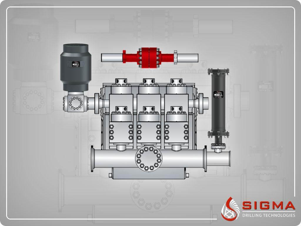
The Charge Free Dampening System™ combines the advanced technologies of Sigma’s Charge Free Dampeners™, Sigma’s Charge Free Conversion Kits®, Sigma’s Charge Free Stabilizer™, and Sigma’s Acoustic Assassin® to create the best available pulsation control solution. When it comes to performance and cost, Sigma’s Charge Free Dampening System™ will out perform more expensive dampeners while significantly reducing weight, size, and cost.
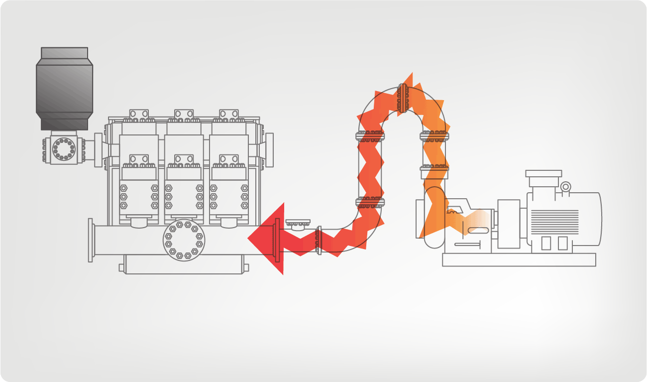
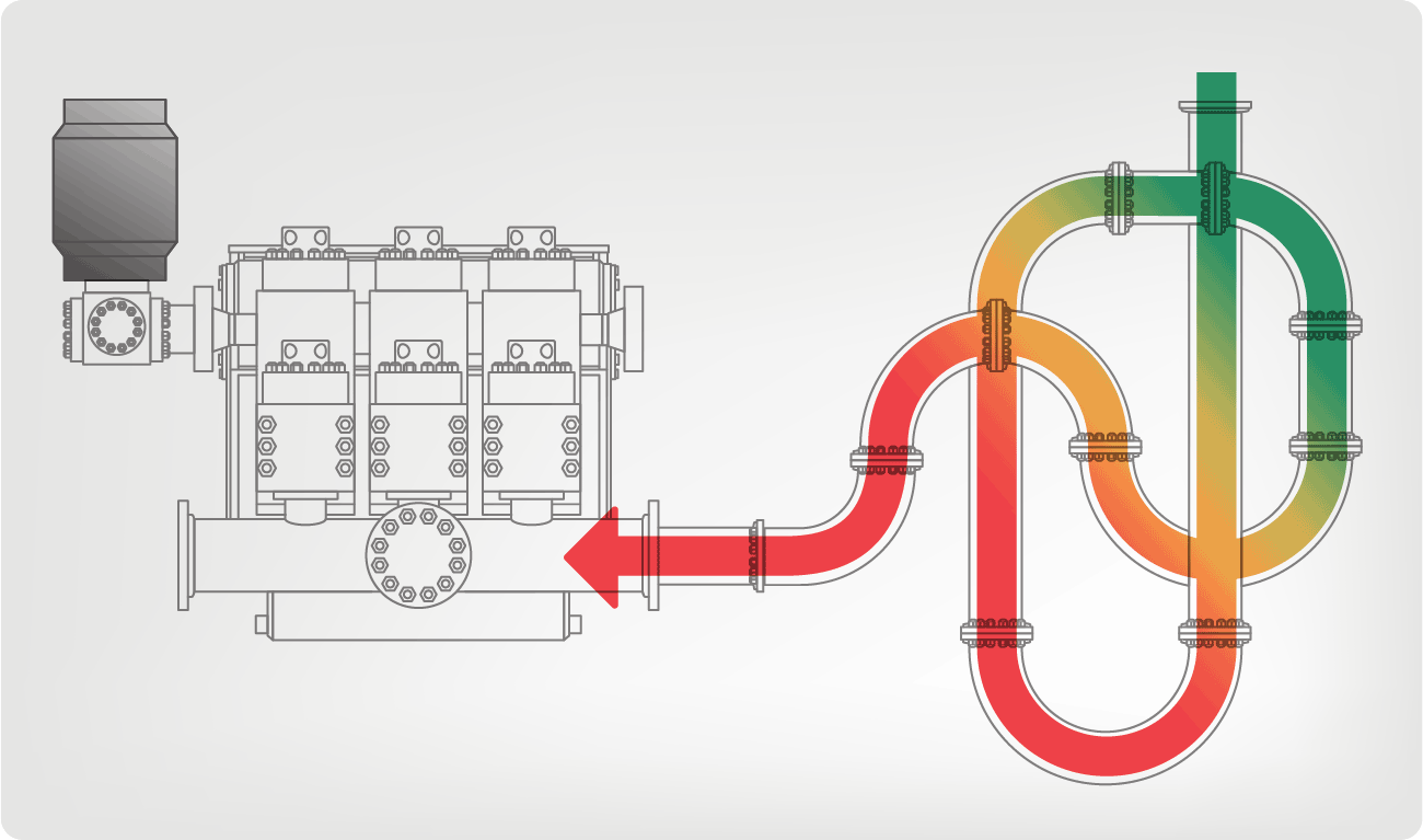
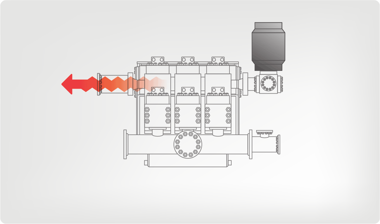
The Charge Free Stabilizer™ was designed to be installed directly before the suction manifold port between the mud pump and the charge pump. Maximizing mud pump performance by eliminating cavitation while isolating both the mud and charge pumps.
The Acoustic Assassin® was designed to be installed between the pump loop manifold and the production line. This fixture is a multi-chambered baffling system that will reduce damaging acoustic resonance generated by reciprocating pumps. The Acoustic Assassin® is an ideal addition to any pulsation control system.
The Charge Free Conversion Kit® is a high performance pulsation control kit that utilizes both compression and kinetic exchange for superior performance over traditional pulsation control methods of the past. With a gigantic increase in surface area, compression tuning, and a design to maximize energy exchange, the CFC Kits control pulsations from the pump while cleaning the signal for MWD tools.
I’ve run into several instances of insufficient suction stabilization on rigs where a “standpipe” is installed off the suction manifold. The thought behind this design was to create a gas-over-fluid column for the reciprocating pump and eliminate cavitation.
When the standpipe is installed on the suction manifold’s deadhead side, there’s little opportunity to get fluid into all the cylinders to prevent cavitation. Also, the reciprocating pump and charge pump are not isolated.
Installing a suction stabilizer from the suction manifold port supports the manifold’s capacity to pull adequate fluid and eliminates the chance of manifold fluid deficiency, which ultimately prevents cavitation.
Another benefit of installing a suction stabilizer is eliminating the negative energies in fluids caused by the water hammer effect from valves quickly closing and opening.
The suction stabilizer’s compressible feature is designed to absorb the negative energies and promote smooth fluid flow. As a result, pump isolation is achieved between the charge pump and the reciprocating pump.
The isolation eliminates pump chatter, and because the reciprocating pump’s negative energies never reach the charge pump, the pump’s expendable life is extended.
Investing in suction stabilizers will ensure your pumps operate consistently and efficiently. They can also prevent most challenges related to pressure surges or pulsations in the most difficult piping environments.
Sigma Drilling Technologies’ Charge Free Suction Stabilizer is recommended for installation. If rigs have gas-charged cartridges installed in the suction stabilizers on the rig, another suggested upgrade is the Charge Free Conversion Kits.

Hydraulic fracturing of downhole formations typically involves pumping slurry containing suspended proppant, gravel or other solids, at relatively high pressures so as to fracture the rocks. Triplex reciprocating pumps, i.e., a pump having a fluid end with three cylinders, are generally used to pump high pressure fracturing fluids downhole, although other pumps such as quintuplex pumps can also be used.
The pumping cycle of the fluid end cylinders is composed of two stages, a suction cycle and a discharge cycle. In the suction cycle a piston moves outward in a packing bore, thereby lowering the fluid pressure in the fluid end cylinder, opening the suction valve and filling the cylinder with the fluid from a suction pipe, which is sometimes referred to as the suction manifold. In some cases, the pressure is 2-3 times the atmospheric pressure, approximately 0.28 MPa (40 psi). In the discharge cycle, the plunger moves forward in the packing bore, thereby progressively increasing the fluid pressure in the pump, closing the suction valve, opening the discharge valve, and the high pressure fluid flows out of the cylinder into the discharge pipe, and in some cases at 14 to 140 MPa (2 to 20 kpsi).
A positive displacement pump used in high pressure pumping services, such as fracturing and the like, typically require suction stabilization such as pulsation control or the like. The large acceleration head caused by the high volume of fluid between the pump cylinder inlet and the actual stabilizer bladder sometimes are difficult for the stabilizer to overcome. The acceleration head is increased with a higher density fluid, such as fracturing fluid or the like. Many suction stabilizers are mounted disadvantageously external of the suction manifold. Appendage pneumatic or air tank suction stabilizers are known, for example, from WO 02064977 (2002) and U.S. Pat. No. 6,089,837 (2000). Those suction stabilizers mounted on the suction manifold are disadvantageously heavy, are high in cost and require high maintenance.
Suction stabilizers may also be formed from or with a closed cell cellular foam material which have a relatively high gas volume without nitrogen charging. According to the manufacturer, proper sizing and setup is important to performance of the pulsation control equipment, whereas the installed location of the pulsation control equipment is critical, and the recommended location for the pulsation control equipment is within 6 times the nominal pipe diameter of the pump manifold connections. Suction stabilizers are not effective when installed away from the pump. Also, closed cell foams cannot always be utilized with certain materials, such as solvents or the like.
In positive displacement pumps such as fracturing pumps, sand, proppant, or other oilfield materials may build up in the suction manifold at lower pumping rates. Such a buildup may reach a point where the buildup may block the entrance to the pump plunger and cause problems including, but not limited to, cavitations in the cylinder or an introduction of large sand concentration into the pump cylinder causing piston hammer and further physical damage to the pump, the engine, and/or the transmission. While it is known to stabilize the velocity variation of the pump suction feed stream using closed cell foam, these suction stabilizers are not always effective in keeping solids from building up.
According to an embodiment, an expandable membrane is positioned along a lower transverse surface of a fluid flow conduit that may contain solids and/or be subject to pressure oscillations. The membrane is inflated with a gas isolated from the fluid flow, and the membrane is alternatingly expanded and contracted to dampen the pressure oscillations and inhibits settling of any solid particles at the lower transverse surface. The expansion and contraction pulsations can be actively applied via external pressurization and depressurization, or caused passively, e.g., by pump stroke cycles in one embodiment where the stabilizer is used in a pump manifold or other conduit associated with the pump.
In an embodiment, a stabilized pump manifold, comprises a manifold in fluid communication with a fluid end of a pump for passage of a process fluid therethrough over a lower surface transverse to vertical, wherein the lower surface is elongated in a direction of fluid flow through the manifold; and a stabilizer comprising a compressible fluid in an expandable membrane elongated along the lower transverse surface in the direction of fluid flow to dampen pressure oscillations within the manifold. In an embodiment where the process fluid being pumped is a slurry, the stabilizer can also inhibit solids settling at the lower transverse surface. In an embodiment, the manifold comprises an inlet to the fluid pump and the stabilizer is a suction stabilizer. In an embodiment, the slurry comprises an oilfield fluid and the solids comprise proppant, sand or a mixture thereof.
In one embodiment, the process fluid comprises a slurry. In one embodiment, the fluid pump comprises a plurality of chambers with reciprocating plungers to alternatingly suction and discharge the slurry. In one embodiment, the manifold comprises a like plurality of branches transverse to the elongated lower surface to supply the slurry to the chambers. In an embodiment, the manifold dissipates an acceleration head during normal operation of the plungers.
In an embodiment, the stabilizer comprises a retainer to secure the membrane adjacent the lower transverse surface. In an embodiment, the stabilizer comprises a tapered insert in the membrane adjacent an attachment fitting.
In another embodiment, a method comprises: reciprocating a plunger in a fluid end of a pump to alternatingly suction and discharge a slurry; passing the slurry through a manifold in fluid communication with the fluid end, wherein the manifold comprises a lower surface transverse to vertical; and alternatingly expanding and contracting a stabilizer comprising a compressible fluid in an expandable membrane elongated along the lower transverse surface to dampen pressure oscillations within the manifold and inhibit solids settling at the lower transverse surface.
In an embodiment, the method further comprises expanding the membrane during the low pressure cycle and compressing the membrane during the high pressure cycle. In an embodiment, the manifold comprises an inlet to the fluid pump and the method further comprises expanding the stabilizer during a low pressure cycle and contracting the stabilizer during a high pressure cycle. In an embodiment, a pressure variation between the low and high pressure cycles is effective to displace solids from the lower transverse surface.
In another embodiment, a method for stabilizing fluid flow in a flow conduit having a lower surface transverse to vertical in contact with the fluid, wherein the fluid contains suspended solid particles and is subject to pressure oscillations, comprises: positioning an expandable membrane along the lower transverse surface; inflating the membrane with a gas isolated from the fluid flow; and alternatingly expanding and contracting the membrane to dampen the pressure oscillations and inhibit settling of the solid particles at the lower transverse surface. In an embodiment, the flow conduit comprises an inlet manifold to a positive displacement pump, the fluid comprises a proppant- or sand-laden oilfield treatment fluid, and the expandable membrane comprises a continuous, elongated chamber such as, for example, a hose.
Referring now to all of the Figures, there is disclosed a pump assembly, indicated generally at 100. The pump assembly 100 comprises a pump 102, coupled to a suitable prime mover (not shown) such as a diesel engine, a gasoline engine, an electric motor, or any suitable prime mover through a suitable transmission (not shown) or the like, as will be appreciated by those skilled in the art. The pump 102 comprises a pump body 104 having a suction manifold 106 attached thereto and in fluid communication with a source of fluid 108 (i.e. “process fluid”) to be pumped, such as a proppant-laden oilfield fluid or the like.
In an embodiment, the proppant used in oilfield treatment fluids, which is also sometimes called gravel or sand, will comprise particle sizes within the ranges from about 0.15 mm to about 2.39 mm (about 8 to about 100 U.S. mesh), more particularly, but not limited to 0.25 to 0.43 mm (40/60 mesh), 0.43 to 0.84 mm (20/40 mesh), 0.84 to 1.19 mm (16/20 mesh), 0.84 to 1.68 mm (12/20 mesh) and 0.84 to 2.39 mm (8/20 mesh) sized materials. In one embodiment, the proppant will be present in the slurry in a concentration of from about 0.12 to about 3 kg/L, e.g., from about 0.12 to about 1.44 kg/L (about 1 PPA to about 25 PPA, preferably from about 1 to about 12 PPA; PPA is “pounds proppant added” per gallon of liquid). In another embodiment, the proppant will be present at greater than 3 kg/L (25 PPA) or greater than 3.6 kg/L (30 PPA), up to a maximum concentration where the slurry can still be pumped. Such proppants may be natural or synthetic (including but not limited to glass beads, ceramic beads, sand, and bauxite), coated, or contain chemicals; more than one may be used sequentially or in mixtures of different sizes or different materials, as is known in the art. The process fluid may also include various additives and chemicals commonly used in well treatment fluids, such as polymers, viscosifiers, surfactants, fluid loss agents, pH stabilizers, breakers, accelerators, friction reducers, and the like.
In an embodiment, a stabilizer device or devices, discussed in more detail below, is provided as part of the pump assembly 100 and is operable to dampen oscillations within a portion of the pump body 104, within the suction manifold 106 and/or suspend solids within the oilfield fluid 108 that may be disposed within the oilfield fluid 108. The stabilizer device or devices may be disposed external to the pump assembly 100 or disposed within the pump body 104, within the suction manifold 106 or at any suitable location within the pump assembly where oscillations may be dampened or solids suspended, as will be appreciated by those skilled in the art.
In an embodiment, a stabilizer or stabilizer device 110, best seen in FIG. 2 is inserted into the interior of the suction manifold 106. In an embodiment, the stabilizer 110 comprises a compliant chamber, preferably defining a continuous, elongated chamber such as, for example, an air or gas pressurized hose disposed in the bottom of the suction manifold 106. The stabilizer 110 may be formed from any suitable compliant material, as will be appreciated by those skilled in the art. The stabilizer device 110 may comprise a compliant blender hose or a petroleum hose made of nitrile rubber, e.g., BUNA-N, hydrogenated nitrile butadiene rubber (HNBR), fluorinated elastomer such as fluorinated ethylene-propylene (FEP) or VITON, synthetic rubber, natural rubber, polyurethane, polyethylene, or any suitable compliant material.
The hose may have a protective cover on the outside to improve its chemical resistance such as a layer or coating of TEFLON polytetrafluoroethylene (PTFE), nylon, FEP, and like. Such a coating or cover may improve the chemical resistance of the stabilizer 110 to fracturing fluids, solvents, etc., and improve the wear resistance of the stabilizer 110. The stabilizer 110 may comprise a gas chamber made of a pliable material suitable for the fluids being pumped. The stabilizer 110 may comprise a bladder or hose, custom built to fit the suction manifold 106. To keep the stabilizer 110 at the bottom of the suction manifold 106 and in a desired orientation, a heavy rod or other smooth shape can be inserted on an interior of the stabilizer 110 or bonded to the outside of the stabilizer 110. The stabilizer 110 may be placed within a perforated cage to allow the pulsations to be damped. The stabilizer 110 may comprise a compliant mechanical bellows. The stabilizer 110 may comprise a section of fire hose or similar suitable material. Those skilled in the art will appreciate that the stabilizer 110 may be a mechanically compliant hose or device such as a chamber or a bellows and the compliance of the stabilizer 110 may be a combination of mechanical and pressurized air compliance
The stabilizer 110 may be pressurized via a pressurizing line 112 from a source 114 of compressible fluid, such as pressurized gas or air. The pressure from the air source 114 may be advantageously varied depending on the specifics of the oilfield services operation of the pump assembly 100 and pump 102. The manifold 106 may be a pre-existing manifold or it may be enlarged to accommodate the stabilizer 110. During operation of the assembly 100, the stabilizer 110 acts as an internal dampener or pulsation bottle and dampens pressure pulsations within the manifold 106. By locating the stabilizer 110 directly within the suction manifold 106, the dampener is located in close proximity to the pump cylinder inlet, advantageously reducing the amount of acceleration head for the assembly 100.
The stabilizer 110 formed from a hose material is more cost effective, it allows the use of the pump for pumping solvents if the proper material is used. The stabilizer 110 may be advantageously retrofitted in existing pumps, such as the pump 102. In those situations where the pump assembly 100 is utilized for pumping liquid CO2or the like, the stabilizer 110 can be removed. The stabilizer hose 110 is advantageously lighter in weight, which is advantageous for mobile applications where legal weight limits is applied, such as on an offshore platform or on a vessel, and it is mechanically simpler and easier to maintain and/or replace while providing good suction stabilization properties for the pump assembly 100.
The stabilizer device 110 also advantageously provides proppant suspension to the assembly 100. When located at the bottom of the manifold 106, the stabilizer device 110 will oscillate and thereby fluidize any sand, proppant, or oilfield material 116, best seen in FIG. 1, that is near or comes in contact with it because the sand, proppant, or oilfield material 116 often settles to the bottom of manifold 106 by gravity during operation of the assembly 100. The pressure pulsations of the stabilizer 110 may be a result of the pressure pulses of the pump plungers causing a pressure differential within the manifold 106, which further causes the compressed gas in the stabilizer 110 to expand and contract. The oscillation of the stabilization device 110 may be externally induced, such as by a vibration device, a moving part, a rotating part, a pulse generator to drive the stabilizer device 110. The oscillation keeps the proppant 116 fluidized and inhibits potential plugging by allowing proppant-laden fluid 108 to flow easily. The stabilizer hose 110 advantageously does not allow proppant 116 to settle in the suction header or manifold 106, providing an even distribution of proppant 116 within the manifold 106 and therefore between plungers, provides less wear on front valve (which may be the first to fail) and reduces the risk of blocking flow to the pump assembly 100 while also providing the suction stabilization noted above. In an embodiment, the stabilization device 110 may be supplemented and/or replaced by a device that induces oscillation distinct from any stabilization device 110 for the purpose of fluidizing any sand, proppant, or oilfield material 116 within the suction header 106 or any suitable location within of the pump assembly 100. Such an oscillation device may be energized separately from the pump or by the power source of the pump.
In an embodiment, the stabilizer 110 comprises a distributed weight, such as a rod, a semi-circular pipe, or the like, attached thereto ensure that the air filled hose is substantially localized at the bottom of the manifold. In an embodiment, the stabilizer 110 is coupled with an internal pulse generator, such as an air pulse generator inside the stabilizer 110, or a remotely located pulse generator that may further improve the capacity of the stabilizer 110 to fluidize the oilfield materials 116.
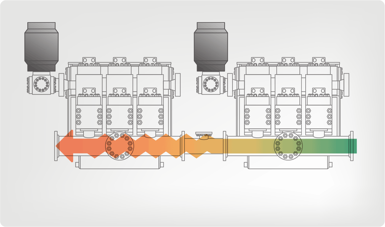
In an embodiment, the stabilizer 110 may be located in the high pressure treating iron (external from the suction manifold 106) to attenuate discharge pressure fluctuations and acoustics. In an embodiment, multiple pumps, such as the pump 102, are connected to a common suction manifold or missile and the stabilizer 110 is disposed inside the low pressure suction piping of the missile. In an embodiment, multiple pumps, such as the pump 102, are connected to a common discharge manifold or missile and the stabilizer 110 is disposed inside the high pressure piping or missile. In an embodiment, the length of the stabilizing device 110 may be varied to tune it to the piping acoustics of its installation. Those skilled in the art will appreciate that the stabilizer 110 may be located in any portion of a pump assembly, such as the pump assembly 100 or its associated piping where it is advantageous to provide pressure stabilization with the use of a compliant chamber or stabilizer 110.
With reference to FIGS. 3-8, another embodiment of the inlet stabilizer device 200 is shown. The stabilizer 200 includes a section of resilient hose 202 disposed along the bottom of the inlet manifold 204 as best seen in FIG. 3. The hose 202 is secured to a metal bar or rod 206 by means of a clamp 208 at the free end of the hose 202 and one or more intermediate clamps 210. The metal bar 206 serves to counteract any buoyant forces and hold the hose 202 adjacent the lower surface of the inlet manifold 204. The end clamp 208 can be provided in a flattened or curved profile which also serves to seal the free end of the hose to keep the air or other compressible fluid from escaping from the hose into the manifold 204, as best seen in FIGS. 5 and 6.
To assemble the inlet stabilizer 200 in the manifold 204 for operation, in one embodiment, the stabilizer 200 is assembled and inserted in the horizontal pipe section of the manifold 204 and the flange 212 secured via threading or bolting, as best seen in FIG. 8. This positions the hose 202 directly beneath the pump fluid end inlets 224 and adjacent the side ports 226. An air supply hose 228 is connected at the air connection fitting 230 of the flange 212, provided with local pressure gauge 231 and/or remote pressure transmitter 232, valve 234, pressure regulator 236 and a source 238 of compressible fluid, such as a tank of compressed air or a compressor or the like. If desired, a pressure stabilizer such as an orifice or porous insert (not shown) may be positioned in the air hose 228 to inhibit motion or vibration which can sometimes result from pressure cycling, especially where the hose 228 is a resilient or flexible material. If desired, a foam or liquid sealant may be injected into the hose 202 to inhibit leaks.
In operation, before introducing the fracturing fluid into the manifold 204 at pressure, the valve 234 is opened to inflate the hose 202 to operating pressure, generally a lower pressure than the peak manifold pressure during pump operation. Then the valve 234 is closed and the pump operated. Pressurization of the manifold 204 then compresses the hose 202 to equalize pressure therein. Compression of the hose 202 corresponds generally to a discharge cycle of the pump. During the suction cycle, the pressure in the manifold may tend to drop and the hose 202 expands to facilitate stabilization of the inlet flow/pressure conditions.
In operation, the change in volume in the hose 202 in each pump cycle corresponds to the delta volume of the pumping operation. The volume of the hose and the initial air pressure are selected to obtain the desired dampening. If the inlet is underdamped the pressure/volume changes are excessive; if overdamped, the volume changes may be insufficient to inhibit solids settling. In one embodiment, the dampening is effective to obtain a peak-to-peak pressure fluctuation of about 35 to 210 kPa (5 to 30 psi), more preferably about 35 to 105 kPa (5 to 15 psi) and especially about 70 kPa (10 psi). The volume of the hose 202 should be sufficient to exceed the pump delta volume in one embodiment, and should not occupy excessive volume so as to interfere with the flow of the fluid to the pump cylinder inlets. In embodiments, the hose 202 is a circular hose although other shapes such as oval or wide and flat are contemplated, and occupies from 2 to 50 percent of the manifold pipe volume fully inflated, preferably 5 to 20 percent of the pipe volume. In one exemplary embodiment the hose has a nominal diameter of 50.8 mm (2 in.) and the horizontal manifold pipe receiving the hose 202 has a nominal diameter of 152 mm (6 in.). In embodiments, the hose 202 is pressurized with air or nitrogen although other compressible fluids could be used, preferably at about 30 to 70 percent of the operating suction gauge pressure, more preferably about half of the suction gauge pressure. In one embodiment the suction gauge pressure is about 400 kPa (60 psig), and in another embodiment about 800 kPa (120 psig). In one embodiment the minimum pressure of the air in the hose is 70 kPa (10 psig). In another embodiment, the inflation pressure of the air in the hose 202 is about 140 to 280 kPa (20 to 40 psig), especially about 210 kPa (30 psig).
One benefit of the inlet stabilizer device of the present invention is the facilitation of particle suspension and inhibition of settling in the suction manifold, which as previously mentioned can cause cavitation if the inlet bores are plugged and/or damage the pump if a slug of sediment enters the fluid cylinder. With reference to FIGS. 9 and 10, FIG. 9 shows the tendency of dense solids 300 to settle out during a fluid discharge cycle when the velocity is lowest in the inlet manifold 302. During this low velocity stage, the pressure is highest in the manifold 302 and the hose 304 is compressed. In the suction cycle, the pressure in the inlet manifold 302 is reduced and the hose 304 is expanded proportionately. The repeated expansion and contraction of the hose 304, preferably in a cyclical pattern corresponding to the pump speed, agitates the fluid and promotes suspension of particles 300 as shown in FIG. 10. The agitation can be augmented during operation or provided while the pump is idled by provided by cycling the hose pressure between expanded and contracted conditions by cycling the pressure of the air above and below the pressure in the manifold 302 at an effective frequency, e.g., the frequency of pressure fluctuations during operation, via the air supply.
a manifold in fluid communication with a fluid end of a pump for passage of a process fluid therethrough over a lower surface transverse to vertical, wherein the lower surface is elongated in a direction of fluid flow through the manifold; and
a stabilizer comprising a compressible fluid in an expandable membrane elongated along the lower transverse surface in the direction of fluid flow to dampen pressure oscillations within the manifold.
C. The stabilized pump manifold of embodiment A or embodiment B wherein the fluid comprises a slurry, the fluid pump comprises a plurality of chambers with reciprocating plungers to alternatingly suction and discharge the slurry, and the manifold comprises a like plurality of branches transverse to the elongated lower surface to supply the slurry to the chambers.
G. The stabilized pump manifold of any one of embodiments A to F wherein the membrane comprises a hose in fluid communication with a source of the compressible fluid at a pressure exceeding a pressure of the slurry in the manifold corresponding to a low pressure cycle.
I. The stabilized pump manifold of any one of embodiments A to H wherein variation of the compressible fluid pressure is adapted to displace solids from the lower transverse surface.
K. The stabilized pump manifold of any one of embodiments A to J wherein the slurry comprises an oilfield fluid and the solids comprise proppant, sand or a mixture thereof.
alternatingly expanding and contracting a stabilizer comprising a compressible fluid in an expandable membrane elongated along the lower transverse surface to dampen pressure oscillations within the manifold and inhibit solids settling at the lower transverse surface.
N. The method of embodiment M wherein the manifold comprises an inlet to the fluid pump and further comprising expanding the stabilizer during a low pressure cycle and contracting the stabilizer during a high pressure cycle.
T. The method of embodiment S wherein the flow conduit comprises an inlet manifold to a positive displacement pump, the fluid comprises a proppant- or sand-laden oilfield treatment fluid, and the expandable membrane defines a continuous, elongated chamber, preferably a hose.
Hydraulic fracturing of downhole formations typically involves pumping slurry containing suspended proppant, gravel or other solids, at relatively high pressures so as to fracture the rocks. Triplex reciprocating pumps, i.e., a pump having a fluid end with three cylinders, are generally used to pump high pressure fracturing fluids downhole, although other pumps such as quintuplex pumps can also be used.
The pumping cycle of the fluid end cylinders is composed of two stages, a suction cycle and a discharge cycle. In the suction cycle a piston moves outward in a packing bore, thereby lowering the fluid pressure in the fluid end cylinder, opening the suction valve and filling the cylinder with the fluid from a suction pipe, which is sometimes referred to as the suction manifold. In some cases, the pressure is 2-3 times the atmospheric pressure, approximately 0.28 MPa (40 psi). In the discharge cycle, the plunger moves forward in the packing bore, thereby progressively increasing the fluid pressure in the pump, closing the suction valve, opening the discharge valve, and the high pressure fluid flows out of the cylinder into the discharge pipe, and in some cases at 14 to 140 MPa (2 to 20 kpsi).
A positive displacement pump used in high pressure pumping services, such as fracturing and the like, typically require suction stabilization such as pulsation control or the like. The large acceleration head caused by the high volume of fluid between the pump cylinder inlet and the actual stabilizer bladder sometimes are difficult for the stabilizer to overcome. The acceleration head is increased with a higher density fluid, such as fracturing fluid or the like. Many suction stabilizers are mounted disadvantageously external of the suction manifold. Appendage pneumatic or air tank suction stabilizers are known, for example, from WO 02064977 (2002) and U.S. Pat. No. 6,089,837 (2000). Those suction stabilizers mounted on the suction manifold are disadvantageously heavy, are high in cost and require high maintenance.
Suction stabilizers may also be formed from or with a closed cell cellular foam material which have a relatively high gas volume without nitrogen charging. According to the manufacturer, proper sizing and setup is important to performance of the pulsation control equipment, whereas the installed location of the pulsation control equipment is critical, and the recommended location for the pulsation control equipment is within 6 times the nominal pipe diameter of the pump manifold connections. Suction stabilizers are not effective when installed away from the pump. Also, closed cell foams cannot always be utilized with certain materials, such as solvents or the like.
In positive displacement pumps such as fracturing pumps, sand, proppant, or other oilfield materials may build up in the suction manifold at lower pumping rates. Such a buildup may reach a point where the buildup may block the entrance to the pump plunger and cause problems including, but not limited to, cavitations in the cylinder or an introduction of large sand concentration into the pump cylinder causing piston hammer and further physical damage to the pump, the engine, and/or the transmission. While it is known to stabilize the velocity variation of the pump suction feed stream using closed cell foam, these suction stabilizers are not always effective in keeping solids from building up.
According to an embodiment, an expandable membrane is positioned along a lower transverse surface of a fluid flow conduit that may contain solids and/or be subject to pressure oscillations. The membrane is inflated with a gas isolated from the fluid flow, and the membrane is alternatingly expanded and contracted to dampen the pressure oscillations and inhibits settling of any solid particles at the lower transverse surface. The expansion and contraction pulsations can be actively applied via external pressurization and depressurization, or caused passively, e.g., by pump stroke cycles in one embodiment where the stabilizer is used in a pump manifold or other conduit associated with the pump.
In an embodiment, a stabilized pump manifold, comprises a manifold in fluid communication with a fluid end of a pump for passage of a process fluid therethrough over a lower surface transverse to vertical, wherein the lower surface is elongated in a direction of fluid flow through the manifold; and a stabilizer comprising a compressible fluid in an expandable membrane elongated along the lower transverse surface in the direction of fluid flow to dampen pressure oscillations within the manifold. In an embodiment where the process fluid being pumped is a slurry, the stabilizer can also inhibit solids settling at the lower transverse surface. In an embodiment, the manifold comprises an inlet to the fluid pump and the stabilizer is a suction stabilizer. In an embodiment, the slurry comprises an oilfield fluid and the solids comprise proppant, sand or a mixture thereof.
In one embodiment, the process fluid comprises a slurry. In one embodiment, the fluid pump comprises a plurality of chambers with reciprocating plungers to alternatingly suction and discharge the slurry. In one embodiment, the manifold comprises a like plurality of branches transverse to the elongated lower surface to supply the slurry to the chambers. In an embodiment, the manifold dissipates an acceleration head during normal operation of the plungers.
In an embodiment, the stabilizer comprises a retainer to secure the membrane adjacent the lower transverse surface. In an embodiment, the stabilizer comprises a tapered insert in the membrane adjacent an attachment fitting.
In another embodiment, a method comprises: reciprocating a plunger in a fluid end of a pump to alternatingly suction and discharge a slurry; passing the slurry through a manifold in fluid communication with the fluid end, wherein the manifold comprises a lower surface transverse to vertical; and alternatingly expanding and contracting a stabilizer comprising a compressible fluid in an expandable membrane elongated along the lower transverse surface to dampen pressure oscillations within the manifold and inhibit solids settling at the lower transverse surface.
In an embodiment, the method further comprises expanding the membrane during the low pressure cycle and compressing the membrane during the high pressure cycle. In an embodiment, the manifold comprises an inlet to the fluid pump and the method further comprises expanding the stabilizer during a low pressure cycle and contracting the stabilizer during a high pressure cycle. In an embodiment, a pressure variation between the low and high pressure cycles is effective to displace solids from the lower transverse surface.
In another embodiment, a method for stabilizing fluid flow in a flow conduit having a lower surface transverse to vertical in contact with the fluid, wherein the fluid contains suspended solid particles and is subject to pressure oscillations, comprises: positioning an expandable membrane along the lower transverse surface; inflating the membrane with a gas isolated from the fluid flow; and alternatingly expanding and contracting the membrane to dampen the pressure oscillations and inhibit settling of the solid particles at the lower transverse surface. In an embodiment, the flow conduit comprises an inlet manifold to a positive displacement pump, the fluid comprises a proppant- or sand-laden oilfield treatment fluid, and the expandable membrane comprises a continuous, elongated chamber such as, for example, a hose. BRIEF DESCRIPTION OF THE SEVERAL VIEWS OF THE DRAWINGS
Referring now to all of the Figures, there is disclosed a pump assembly, indicated generally at 100. The pump assembly 100 comprises a pump 102, coupled to a suitable prime mover (not shown) such as a diesel engine, a gasoline engine, an electric motor, or any suitable prime mover through a suitable transmission (not shown) or the like, as will be appreciated by those skilled in the art. The pump 102 comprises a pump body 104 having a suction manifold 106 attached thereto and in fluid communication with a source of fluid 108 (i.e. “process fluid”) to be pumped, such as a proppant-laden oilfield fluid or the like.
In an embodiment, the proppant used in oilfield treatment fluids, which is also sometimes called gravel or sand, will comprise particle sizes within the ranges from about 0.15 mm to about 2.39 mm (about 8 to about 100 U.S. mesh), more particularly, but not limited to 0.25 to 0.43 mm (40/60 mesh), 0.43 to 0.84 mm (20/40 mesh), 0.84 to 1.19 mm (16/20 mesh), 0.84 to 1.68 mm (12/20 mesh) and 0.84 to 2.39 mm (8/20 mesh) sized materials. In one embodiment, the proppant will be present in the slurry in a concentration of from about 0.12 to about 3 kg/L, e.g., from about 0.12 to about 1.44 kg/L (about 1 PPA to about 25 PPA, preferably from about 1 to about 12 PPA; PPA is “pounds proppant added” per gallon of liquid). In another embodiment, the proppant will be present at greater than 3 kg/L (25 PPA) or greater than 3.6 kg/L (30 PPA), up to a maximum concentration where the slurry can still be pumped. Such proppants may be natural or synthetic (including but not limited to glass beads, ceramic beads, sand, and bauxite), coated, or contain chemicals; more than one may be used sequentially or in mixtures of different sizes or different materials, as is known in the art. The process fluid may also include various additives and chemicals commonly used in well treatment fluids, such as polymers, viscosifiers, surfactants, fluid loss agents, pH stabilizers, breakers, accelerators, friction reducers, and the like.
In an embodiment, a stabilizer device or devices, discussed in more detail below, is provided as part of the pump assembly 100 and is operable to dampen oscillations within a portion of the pump body 104, within the suction manifold 106 and/or suspend solids within the oilfield fluid 108 that may be disposed within the oilfield fluid 108. The stabilizer device or devices may be disposed external to the pump assembly 100 or disposed within the pump body 104, within the suction manifold 106 or at any suitable location within the pump assembly where oscillations may be dampened or solids suspended, as will be appreciated by those skilled in the art.
In an embodiment, a stabilizer or stabilizer device 110, best seen in FIG. 2 is inserted into the interior of the suction manifold 106. In an embodiment, the stabilizer 110 comprises a compliant chamber, preferably defining a continuous, elongated chamber such as, for example, an air or gas pressurized hose disposed in the bottom of the suction manifold 106. The stabilizer 110 may be formed from any suitable compliant material, as will be appreciated by those skilled in the art. The stabilizer device 110 may comprise a compliant blender hose or a petroleum hose made of nitrile rubber, e.g., BUNA-N, hydrogenated nitrile butadiene rubber (HNBR), fluorinated elastomer such as fluorinated ethylene-propylene (FEP) or VITON, synthetic rubber, natural rubber, polyurethane, polyethylene, or any suitable compliant material.
The hose may have a protective cover on the outside to improve its chemical resistance such as a layer or coating of TEFLON polytetrafluoroethylene (PTFE), nylon, FEP, and like. Such a coating or cover may improve the chemical resistance of the stabilizer 110 to fracturing fluids, solvents, etc., and improve the wear resistance of the stabilizer 110. The stabilizer 110 may comprise a gas chamber made of a pliable material suitable for the fluids being pumped. The stabilizer 110 may comprise a bladder or hose, custom built to fit the suction manifold 106. To keep the stabilizer 110 at the bottom of the suction manifold 106 and in a desired orientation, a heavy rod or other smooth shape can be inserted on an interior of the stabilizer 110 or bonded to the outside of the stabilizer 110. The stabilizer 110 may be placed within a perforated cage to allow the pulsations to be damped. The stabilizer 110 may comprise a compliant mechanical bellows. The stabilizer 110 may comprise a section of fire hose or similar suitable material. Those skilled in the art will appreciate that the stabilizer 110 may be a mechanically compliant hose or device such as a chamber or a bellows and the compliance of the stabilizer 110 may be a combination of mechanical and pressurized air compliance
The stabilizer 110 may be pressurized via a pressurizing line 112 from a source 114 of compressible fluid, such as pressurized gas or air. The pressure from the air source 114 may be advantageously varied depending on the specifics of the oilfield services operation of the pump assembly 100 and pump 102. The manifold 106 may be a pre-existing manifold or it may be enlarged to accommodate the stabilizer 110. During operation of the assembly 100, the stabilizer 110 acts as an internal dampener or pulsation bottle and dampens pressure pulsations within the manifold 106. By locating the stabilizer 110 directly within the suction manifold 106, the dampener is located in close proximity to the pump cylinder inlet, advantageously reducing the amount of acceleration head for the assembly 100.
The stabilizer 110 formed from a hose material is more cost effective, it allows the use of the pump for pumping solvents if the proper material is used. The stabilizer 110 may be advantageously retrofitted in existing pumps, such as the pump 102. In those situations where the pump assembly 100 is utilized for pumping liquid CO2or the like, the stabilizer 110 can be removed. The stabilizer hose 110 is advantageously lighter in weight, which is advantageous for mobile applications where legal weight limits is applied, such as on an offshore platform or on a vessel, and it is mechanically simpler and easier to maintain and/or replace while providing good suction stabilization properties for the pump assembly 100.
The stabilizer device 110 also advantageously provides proppant suspension to the assembly 100. When located at the bottom of the manifold 106, the stabilizer device 110 will oscillate and thereby fluidize any sand, proppant, or oilfield material 116, best seen in FIG. 1, that is near or comes in contact with it because the sand, proppant, or oilfield material 116 often settles to the bottom of manifold 106 by gravity during operation of the assembly 100. The pressure pulsations of the stabilizer 110 may be a result of the pressure pulses of the pump plungers causing a pressure differential within the manifold 106, which further causes the compressed gas in the stabilizer 110 to expand and contract. The oscillation of the stabilization device 110 may be externally induced, such as by a vibration device, a moving part, a rotating part, a pulse generator to drive the stabilizer device 110. The oscillation keeps the proppant 116 fluidized and inhibits potential plugging by allowing proppant-laden fluid 108 to flow easily. The stabilizer hose 110 advantageously does not allow proppant 116 to settle in the suction header or manifold 106, providing an even distribution of proppant 116 within the manifold 106 and therefore between plungers, provides less wear on front valve (which may be the first to fail) and reduces the risk of blocking flow to the pump assembly 100 while also providing the suction stabilization noted above. In an embodiment, the stabilization device 110 may be supplemented and/or replaced by a device that induces oscillation distinct from any stabilization device 110 for the purpose of fluidizing any sand, proppant, or oilfield material 116 within the suction header 106 or any suitable location within of the pump assembly 100. Such an oscillation device may be energized separately from the pump or by the power source of the pump.
In an embodiment, the stabilizer 110 comprises a distributed weight, such as a rod, a semi-circular pipe, or the like, attached thereto ensure that the air filled hose is substantially localized at the bottom of the manifold. In an embodiment, the stabilizer 110 is coupled with an internal pulse generator, such as an air pulse generator inside the stabilizer 110, or a remotely located pulse generator that may further improve the capacity of the stabilizer 110 to fluidize the oilfield materials 116.
In an embodiment, the stabilizer 110 may be located in the high pressure treating iron (external from the suction manifold 106) to attenuate discharge pressure fluctuations and acoustics. In an embodiment, multiple pumps, such as the pump 102, are connected to a common suction manifold or missile and the stabilizer 110 is disposed inside the low pressure suction piping of the missile. In an embodiment, multiple pumps, such as the pump 102, are connected to a common discharge manifold or missile and the stabilizer 110 is disposed inside the high pressure piping or missile. In an embodiment, the length of the stabilizing device 110 may be varied to tune it to the piping acoustics of its installation. Those skilled in the art will appreciate that the stabilizer 110 may be located in any portion of a pump assembly, such as the pump assembly 100 or its associated piping where it is advantageous to provide pressure stabilization with the use of a compliant chamber or stabilizer 110.
With reference to FIGS. 3-8, another embodiment of the inlet stabilizer device 200 is shown. The stabilizer 200 includes a section of resilient hose 202 disposed along the bottom of the inlet manifold 204 as best seen in FIG. 3. The hose 202 is secured to a metal bar or rod 206 by means of a clamp 208 at the free end of the hose 202 and one or more intermediate clamps 210. The metal bar 206 serves to counteract any buoyant forces and hold the hose 202 adjacent the lower surface of the inlet manifold 204. The end clamp 208 can be provided in a flattened or curved profile which also serves to seal the free end of the hose to keep the air or other compressible fluid from escaping from the hose into the manifold 204, as best seen in FIGS. 5 and 6.
To assemble the inlet stabilizer 200 in the manifold 204 for operation, in one embodiment, the stabilizer 200 is assembled and inserted in the horizontal pipe section of the manifold 204 and the flange 212 secured via threading or bolting, as best seen in FIG. 8. This positions the hose 202 directly beneath the pump fluid end inlets 224 and adjacent the side ports 226. An air supply hose 228 is connected at the air connection fitting 230 of the flange 212, provided with local pressure gauge 231 and/or remote pressure transmitter 232, valve 234, pressure regulator 236 and a source 238 of compressible fluid, such as a tank of compressed air or a compressor or the like. If desired, a pressure stabilizer such as an orifice or porous insert (not shown) may be positioned in the air hose 228 to inhibit motion or vibration which can sometimes result from pressure cycling, especially where the hose 228 is a resilient or flexible material. If desired, a foam or liquid sealant may be injected into the hose 202 to inhibit leaks.
In operation, before introducing the fracturing fluid into the manifold 204 at pressure, the valve 234 is opened to inflate the hose 202 to operating pressure, generally a lower pressure than the peak manifold pressure during pump operation. Then the valve 234 is closed and the pump operated. Pressurization of the manifold 204 then compresses the hose 202 to equalize pressure therein. Compression of the hose 202 corresponds generally to a discharge cycle of the pump. During the suction cycle, the pressure in the manifold may tend to drop and the hose 202 expands to facilitate stabilization of the inlet flow/pressure conditions.
In operation, the change in volume in the hose 202 in each pump cycle corresponds to the delta volume of the pumping operation. The volume of the hose and the initial air pressure are selected to obtain the desired dampening. If the inlet is underdamped the pressure/volume changes are excessive; if overdamped, the volume changes may be insufficient to inhibit solids settling. In one embodiment, the dampening is effective to obtain a peak-to-peak pressure fluctuation of about 35 to 210 kPa (5 to 30 psi), more preferably about 35 to 105 kPa (5 to 15 psi) and especially about 70 kPa (10 psi). The volume of the hose 202 should be sufficient to exceed the pump delta volume in one embodiment, and should not occupy excessive volume so as to interfere with the flow of the fluid to the pump cylinder inlets. In embodiments, the hose 202 is a circular hose although other shapes such as oval or wide and flat are contemplated, and occupies from 2 to 50 percent of the manifold pipe volume fully inflated, preferably 5 to 20 percent of the pipe volume. In one exemplary embodiment the hose has a nominal diameter of 50.8 mm (2 in.) and the horizontal manifold pipe receiving the hose 202 has a nominal diameter of 152 mm (6 in.). In embodiments, the hose 202 is pressurized with air or nitrogen although other compressible fluids could be used, preferably at about 30 to 70 percent of the operating suction gauge pressure, more preferably about half of the suction gauge pressure. In one embodiment the suction gauge pressure is about 400 kPa (60 psig), and in another embodiment about 800 kPa (120 psig). In one embodiment the minimum pressure of the air in the hose is 70 kPa (10 psig). In another embodiment, the inflation pressure of the air in the hose 202 is about 140 to 280 kPa (20 to 40 psig), especially about 210 kPa (30 psig).
One benefit of the inlet stabilizer device of the present invention is the facilitation of particle suspension and inhibition of settling in the suction manifold, which as previously mentioned can cause cavitation if the inlet bores are plugged and/or damage the pump if a slug of sediment enters the fluid cylinder. With reference to FIGS. 9 and 10, FIG. 9 shows the tendency of dense solids 300 to settle out during a fluid discharge cycle when the velocity is lowest in the inlet manifold 302. During this low velocity stage, the pressure is highest in the manifold 302 and the hose 304 is compressed. In the suction cycle, the pressure in the inlet manifold 302 is reduced and the hose 304 is expanded proportionately. The repeated expansion and contraction of the hose 304, preferably in a cyclical pattern corresponding to the pump speed, agitates the fluid and promotes suspension of particles 300 as shown in FIG. 10. The agitation can be augmented during operation or provided while the pump is idled by provided by cycling the hose pressure between expanded and contracted conditions by cycling the pressure of the air above and below the pressure in the manifold 302 at an effective frequency, e.g., the frequency of pressure fluctuations during operation, via the air supply.
a manifold in fluid communication with a fluid end of a pump for passage of a process fluid therethrough over a lower surface transverse to vertical, wherein the lower surface is elongated in a direction of fluid flow through the manifold; and
a stabilizer comprising a compressible fluid in an expandable membrane elongated along the lower transverse surface in the direction of fluid flow to dampen pressure oscillations within the manifold.
C. The stabilized pump manifold of embodiment A or embodiment B wherein the fluid comprises a slurry, the fluid pump comprises a plurality of chambers with reciprocating plungers to alternatingly suction and discharge the slurry, and the manifold comprises a like plurality of branches transverse to the elongated lower surface to supply the slurry to the chambers.
G. The stabilized pump manifold of any one of embodiments A to F wherein the membrane comprises a hose in fluid communication with a source of the compressible fluid at a pressure exceeding a pressure of the slurry in the manifold corresponding to a low pressure cycle.
I. The stabilized pump manifold of any one of embodiments A to H wherein variation of the compressible fluid pressure is adapted to displace solids from the lower transverse surface.
K. The stabilized pump manifold of any one of embodiments A to J wherein the slurry comprises an oilfield fluid and the solids comprise proppant, sand or a mixture thereof.
alternatingly expanding and contracting a stabilizer comprising a compressible fluid in an expandable membrane elongated along the lower transverse surface to dampen pressure oscillations within the manifold and inhibit solids settling at the lower transverse surface.
N. The method of embodiment M wherein the manifold comprises an inlet to the fluid pump and further comprising expanding the stabilizer during a low pressure cycle and contracting the stabilizer during a high pressure cycle.
T. The method of embodiment S wherein the flow conduit comprises an inlet manifold to a positive displacement pump, the fluid comprises a proppant- or sand-laden oilfield treatment fluid, and the expandable membrane defines a continuous, elongated chamber, preferably a hose.
Buy high-capacity pump suction stabilizer that are guaranteed to keep your appliances up and running in perfect condition from Alibaba.com. These pump suction stabilizer are offered from the best and most energy-efficient brands and provides users with an elevated experience. These pump suction stabilizer are designed to ensure safety and stability and are available in a number of variants.
pump suction stabilizer offered on Alibaba.com have many necessary and interesting features such as fail-safe circuit protection and cut-off points. These pump suction stabilizer have a high range and are likely to fit most home and commercial purposes. These pump suction stabilizer have finely crafted exteriors to ensure that there is no risk of shock or accidents. Some of these items even have LED displays for a smoother experience and greater transparency.
pump suction stabilizer are suitable for all sorts of large appliances and do not malfunction easily. They require very limited maintenance and not much has to be spent on their upkeep. pump suction stabilizer ensure that your expensive appliances and machines do not get damaged due to fluctuations and are inevitable for any home or commercial enterprise that engages multiple electronic items. pump suction stabilizer on the site offer optimal performance at economical prices.
Choose the pump suction stabilizer that best suit your needs, whether for home, office or industry. pump suction stabilizer suppliers are sure to want to snap up this attractive chance to buy quality items at discounted prices. Grab these amazing deals today.
Performance Pulsation Control is meeting the suction stabilizer needs of clients across the country. We can tailor a suction stabilizer and suction pulsation dampener to fit the specific output requirements of any commercial industry that relies on consistent and precise pump solutions. Some of the customization possibilities you’ll find for your business applications include:
Triplex mud pumps pump drilling mud during well operations. An example of a typical triplex mud pump 10 shown in FIG. 1A has a power assembly 12, a crosshead assembly 14, and a fluid assembly 16. Electric motors (not shown) connect to a pinion shaft 30 that drives the power assembly 12. The crosshead assembly 14 converts the rotational movement of the power assembly 12 into reciprocating movement to actuate internal pistons or plungers of the fluid assembly 16. Being triplex, the pump"s fluid assembly 16 has three internal pistons to pump the mud.
As shown in FIG. 1B, the pump"s power assembly 14 has a crankshaft 20 supported at its ends by double roller bearings 22. Positioned along its intermediate extent, the crankshaft 20 has three eccentric sheaves 24-1 . . . 24-3, and three connecting rods 40 mount onto these sheaves 24 with cylindrical roller bearings 26. These connecting rods 40 connect by extension rods (not shown) and the crosshead assembly (14) to the pistons of the pump"s fluid assembly 16.
In addition to the sheaves, the crankshaft 20 also has a bull gear 28 positioned between the second and third sheaves 24-2 and 24-3. The bull gear 28 interfaces with the pinion shaft (30) and drives the crankshaft 20"s rotation. As shown particularly in FIG. 1C, the pinion shaft 30 also mounts in the power assembly 14 with roller bearings 32 supporting its ends. When electric motors couple to the pinion shaft"s ends 34 and rotate the pinion shaft 30, a pinion gear 38 interfacing with the crankshaft"s bull gear 28 drives the crankshaft (20), thereby operating the pistons of the pump"s fluid assembly 16.
When used to pump mud, the triplex mud pump 10 produces flow that varies by approximately 23%. For example, the pump 10 produces a maximum flow level of about 106% during certain crankshaft angles and produces a minimum flow level of 83% during other crankshaft angles, resulting in a total flow variation of 23% as the pump"s pistons are moved in differing exhaust strokes during the crankshaft"s rotation. Because the total flow varies, the pump 10 tends to produce undesirable pressure changes or “noise” in the pumped mud. In turn, this noise interferes with downhole telemetry and other techniques used during measurement-while-drilling (MWD) and logging-while-drilling (LWD) operations.
In contrast to mud pumps, well-service pumps (WSP) are also used during well operations. A well service pump is used to pump fluid at higher pressures than those used to pump mud. Therefore, the well service pumps are typically used to pump high pressure fluid into a well during frac operations or the like. An example of a well-service pump 50 is shown in FIG. 2. Here, the well service pump 50 is a quintuplex well service pump, although triplex well service pumps are also used. The pump 50 has a power assembly 52, a crosshead assembly 54, and a fluid assembly 56. A gear reducer 53 on one side of the pump 50 connects a drive (not shown) to the power assembly 52 to drive the pump 50.
As shown in FIG. 3, the pump"s power assembly 52 has a crankshaft 60 with five crankpins 62 and an internal main bearing sheave 64. The crankpins 62 are offset from the crankshaft 60"s axis of rotation and convert the rotation of the crankshaft 60 in to a reciprocating motion for operating pistons (not shown) in the pump"s fluid assembly 56. Double roller bearings 66 support the crankshaft 60 at both ends of the power assembly 52, and an internal double roller bearing 68 supports the crankshaft 60 at its main bearing sheave 64. One end 61 of the crankshaft 60 extends outside the power assembly 52 for coupling to the gear reducer (53; FIG. 2) and other drive components.
As shown in FIG. 4A, connecting rods 70 connect from the crankpins 62 to pistons or plungers 80 via the crosshead assembly 54. FIG. 4B shows a typical connection of a connecting rod 70 to a crankpin 62 in the well service pump 50. As shown, a bearing cap 74 fits on one side of the crankpin 62 and couples to the profiled end of the connecting rod 70. To reduce friction, the connection uses a sleeve bearing 76 between the rod 70, bearing cap 74, and crankpin 62. From the crankpin 62, the connecting rod 70 connects to a crosshead 55 using a wrist pin 72 as shown in FIG. 4A. The wrist pin 72 allows the connecting rod 70 to pivot with respect to the crosshead 55, which in turn is connected to the plunger 80.
In use, an electric motor or an internal combustion engine (such as a diesel engine) drives the pump 50 by the gear reducer 53. As the crankshaft 60 turns, the crankpins 62 reciprocate the connecting rods 70. Moved by the rods 70, the crossheads 55 reciprocate inside fixed cylinders. In turn, the plunger 80 coupled to the crosshead 55 also reciprocates between suction and power strokes in the fluid assembly 56. Withdrawal of a plunger 80 during a suction stroke pulls fluid into the assembly 56 through the input valve 82 connected to an inlet hose or pipe (not shown). Subsequently pushed during the power stroke, the plunger 80 then forces the fluid under pressure out through the output valve 84 connected to an outlet hose or pipe (not shown).
In contrast to using a crankshaft for a quintuplex well-service pump that has crankpins 62 as discussed above, another type of quintuplex well-service pump uses eccentric sheaves on a direct drive crankshaft. FIG. 4C is an isolated view of such a crankshaft 90 having eccentric sheaves 92-1 . . . 92-5 for use in a quintuplex well-service pump. External main bearings (not shown) support the crankshaft 90 at its ends 96 in the well-service pumps housing (not shown). To drive the crankshaft 90, one end 91 extends beyond the pumps housing for coupling to drive components, such as a gear box. The crankshaft 90 has five eccentric sheaves 92-1 . . . 92-5 for coupling to connecting rods (not shown) with roller bearings. The crankshaft 90 also has two internal main bearing sheaves 94-1, 94-2 for internal main bearings used to support the crankshaft 90 in the pump"s housing.
In the past, quintuplex well-service pumps used for pumping frac fluid or the like have been substituted for mud pumps during drilling operations to pump mud. Unfortunately, the well-service pump has a shorter service life compared to the conventional triplex mud pumps, making use of the well-service pump as a mud pump less desirable in most situations. In addition, a quintuplex well-service pump produces a great deal of white noise that interferes with MWD and LWD operations, further making the pump"s use to pump mud less desirable in most situations. Furthermore, the well-service pump is configured for direct drive by a motor and gear box directly coupling on one end of the crankshaft. This direct coupling limits what drives can be used with the pump. Moreover, the direct drive to the crankshaft can produce various issues with noise, balance, wear, and other associated problems that make use of the well-service pump to pump mud less desirable.
One might expect to provide a quintuplex mud pump by extending the conventional arrangement of a triplex mud pump (e.g., as shown in FIG. 1B) to include components for two additional pistons or plungers. However, the actual design for a quintuplex mud pump is not as easy as extending the conventional arrangement, especially in light of the requirements for a mud pump"s operation such as service life, noise levels, crankshaft deflection, balance, and other considerations. As a result, acceptable implementation of a quintuplex mud pump has not been achieved in the art during the long history of mud pump design.
What is needed is an efficient mud pump that has a long service life and that produces low levels of white noise during operation so as not to interfere with MWD and LWD operations while pumping mud in a well.
A quintuplex mud pump is a continuous duty, reciprocating plunger/piston pump. The mud pump has a crankshaft supported in the pump by external main bearings and uses internal gearing and a pinion shaft to drive the crankshaft. Five eccentric sheaves and two internal main bearing sheaves are provided on the crankshaft. Each of the main bearing sheaves supports the intermediate extent of crankshaft using bearings. One main bearing sheave is disposed between the second and third eccentric


 8613371530291