
mud pump suction stabilizer quotation

Performance Pulsation Control is meeting the suction stabilizer needs of clients across the country. We can tailor a suction stabilizer and suction pulsation dampener to fit the specific output requirements of any commercial industry that relies on consistent and precise pump solutions. Some of the customization possibilities you’ll find for your business applications include:
Buy high-capacity pump suction stabilizer that are guaranteed to keep your appliances up and running in perfect condition from Alibaba.com. These pump suction stabilizer are offered from the best and most energy-efficient brands and provides users with an elevated experience. These pump suction stabilizer are designed to ensure safety and stability and are available in a number of variants.
pump suction stabilizer offered on Alibaba.com have many necessary and interesting features such as fail-safe circuit protection and cut-off points. These pump suction stabilizer have a high range and are likely to fit most home and commercial purposes. These pump suction stabilizer have finely crafted exteriors to ensure that there is no risk of shock or accidents. Some of these items even have LED displays for a smoother experience and greater transparency.
pump suction stabilizer are suitable for all sorts of large appliances and do not malfunction easily. They require very limited maintenance and not much has to be spent on their upkeep. pump suction stabilizer ensure that your expensive appliances and machines do not get damaged due to fluctuations and are inevitable for any home or commercial enterprise that engages multiple electronic items. pump suction stabilizer on the site offer optimal performance at economical prices.
Choose the pump suction stabilizer that best suit your needs, whether for home, office or industry. pump suction stabilizer suppliers are sure to want to snap up this attractive chance to buy quality items at discounted prices. Grab these amazing deals today.
Buy high-capacity pump suction stabilizers that are guaranteed to keep your appliances up and running in perfect condition from Alibaba.com. These pump suction stabilizers are offered from the best and most energy-efficient brands and provides users with an elevated experience. These pump suction stabilizers are designed to ensure safety and stability and are available in a number of variants.
pump suction stabilizers offered on Alibaba.com have many necessary and interesting features such as fail-safe circuit protection and cut-off points. These pump suction stabilizers have a high range and are likely to fit most home and commercial purposes. These pump suction stabilizers have finely crafted exteriors to ensure that there is no risk of shock or accidents. Some of these items even have LED displays for a smoother experience and greater transparency.
pump suction stabilizers are suitable for all sorts of large appliances and do not malfunction easily. They require very limited maintenance and not much has to be spent on their upkeep. pump suction stabilizers ensure that your expensive appliances and machines do not get damaged due to fluctuations and are inevitable for any home or commercial enterprise that engages multiple electronic items. pump suction stabilizers on the site offer optimal performance at economical prices.
Choose the pump suction stabilizers that best suit your needs, whether for home, office or industry. pump suction stabilizers suppliers are sure to want to snap up this attractive chance to buy quality items at discounted prices. Grab these amazing deals today.

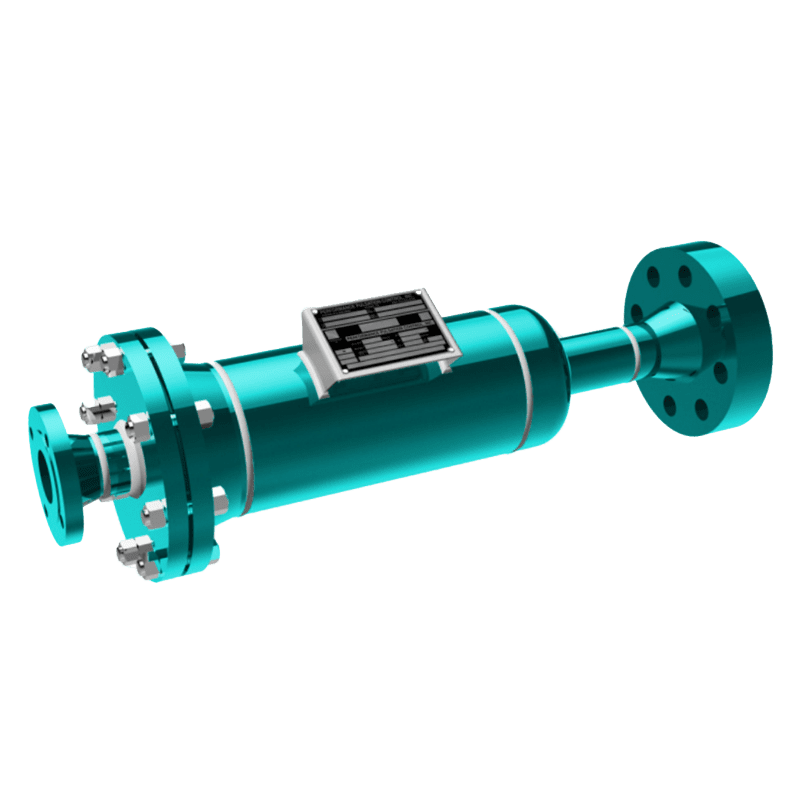
Pulsation dampeners, also known as pulsation stabilizers, accumulators, arrestors and surge suppressors, are used to control and minimize the pulsations that result from a pressurized system’s pump stroking action. They increase system efficiency, performance, and pump life; decrease maintenance costs and down time; and protect pipes, meters, valves and instrumentation from pulsation, vibration, and hydraulic shock.
Most pulsation dampeners use a bladder, or bellows, to separate the process fluid from a compressible gas. During the pump’s discharge stroke, fluid pressure displaces the bladder or bellows and compresses the trapped gas. During the following cycle, the momentary interruption of fluid flow causes the compressed gas to expand, forcing the bladder or bellows to push the accumulated fluid back into the discharge line.
Generally, the majority of pump pulsation problems can be traced to and remedied on the suction side of a pump, even though some symptoms may show up on the discharge side In feeding the pump. It is extremely important to maintain a steady flow of fluid through the suction valves. Also, the fluid column must attach thoroughly to the face of the plunger to achieve complete cylinder fill on the suction stroke.
Determine the amount of fluid a pump will be moving, at what speed, and at what pressure. Indicators: Number of plungers, Bore, Stroke Length, RPM Suction & Discharge Pressure
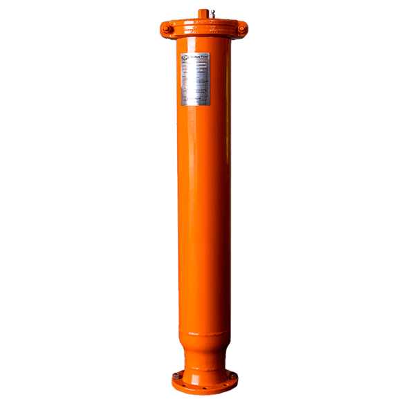
The pulsation stabilizer opening should be the same size as the opening on the side of the pump on which it will operate. This will guard against unwanted acceleration or deceleration of fluid as it passes between the pump and stabilizer. Always defer to the next larger size should an exact match not be available.
Before installing any pulsation stabilizer or discharge dampener, be sure to consider the makeup of the overall system. Be aware of system characteristics that could effect a stabilizer decision, such as other pumps running in line, upstream/downstream pressure considerations, fluid composition and temperature, such as crude oil, salt water or drilling mud, or multiple pumps on a common header.
NOTE: The stabilizer opening should be the same size as the pump opening or larger. flanged and threaded Sizes are available from 1" to 8" - depending on the Series.

The reciprocating pump’s cylinders pull its fluids from the suction manifold. When the suction manifold has trouble refilling with fluid, the cylinders will take in vapor and create a void in the cylinder. This is called cavitation, and it produces a very adverse reaction that is transferred into the fluids.
When you install a suction stabilizer off the suction manifold port, this gives the manifold extra capacity to pull fluid from and eliminates the manifold’s opportunity to lack fluids, thus eliminating cavitation.
The second benefit the suction stabilizer offers is eliminating negative forces in the fluids produced by the pump’s valves opening and closing rapidly, creating a water hammer effect. The suction stabilizer’s compressible element is designed to absorb these energies and smooth out the fluid flow. This causes pump isolation or, in other words, the reciprocating pump is now isolated from the charge pump, and vice versa. The negative energies produced by the reciprocating pump never make it back to the charge pump, which extends the life of the pump expendables.
Invented to address the pitfalls standpipes have, cartridge vessels made it possible for gas to be contained by separating gases from drilling fluids with a rubber membrane. Unfortunately, your problem with cartridge vessels is they will eventually fail. When they do, compressibility is lost, rendering the suction stabilizer incapable of absorbing any energy and leaving the vessel utterly ineffective. Every time a cartridge vessel fails, it leaves the reciprocating pump less efficient, which ultimately costs time, money, and human resources, commodities that are precious on a drilling rig.
Even though the cartridge vessel is an improvement above the standpipe, the misinformation or assumptions that people make regarding the stabilizers still render it pretty ineffective. One common mistake is installing a stabilizer in place of a standpipe, resulting in an improper location. A stabilizer’s intended design and purpose are installed directly off the suction manifold between the reciprocating pump and the charge pump.

Pulsation problems often start on the suction side. Pulsation or cavitation is caused by the variation of fluid movement within a contained system. Since fluid is non-compressible, the energy produced by this pulsation or cavitation must be compensated for. With the introduction of pulsation equipment into a system this energy now has a place to expend itself. Without the pulsation equipment involved in your pumping system, the pulsation or cavitation that is present can lead to the following:
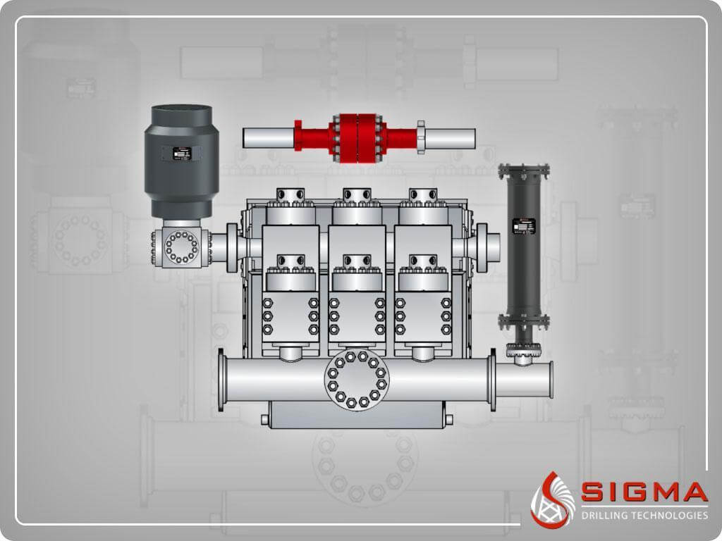
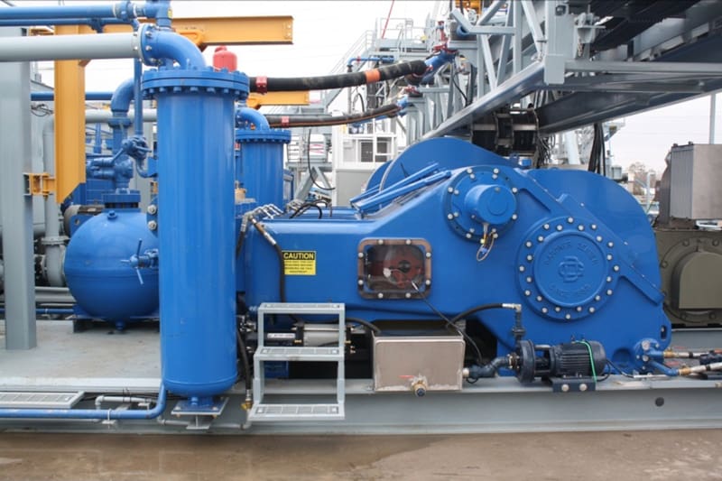
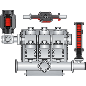
Powerful, durable and lightweight, the GD-1600 is ideal for offshore applications, but features the versatility to be used in skid, or truck mounted configurations, even being staggered for a double pump unit within the road legal 102” limit. A patented connecting rod assembly allows for maximum thrust bearing area, and standard autofrettaged fluid end options provide exceptional fluid end life.
For more information about pulsation dampeners, we sat down with Brandon Dalrymple and Nathan Ackeret fromBlacoh Fluid Control(manufacturer of pulsation dampeners, surge suppressors, and inlet stabilizers), and asked them to answer a few of our customers’ most common questions about pulsation dampeners.
Pulsation dampeners absorb the energy from the pulse wave created by a positive displacement pump, much like a shock absorber on a vehicle. Absorbing those pulse waves protects pipe welds and supports, and system components from damage due to pressure or excess movement.
Pulsation dampeners are commonly used wherever a positive displacement pump discharges flow in an unsteady manner, and where the pulse is not desired for the piping system. Air operated double diaphragm, metering and hose/peristaltic pumps typically benefit from a pulsation dampener.
The type of pulsation dampener used is typically defined by where they are placed in the system, and what they need to do. For example, "pulsation dampeners" are on the downstream side of the pump, "inlet stabilizers" are on the inlet side of the pump, and an accumulator or "surge suppressor" is used next to a valve or other device that restricts the flow in a system.
This video shows where you would place an inlet stabilizer, and how it is used to reduce the pulsation with an air operated diaphragm pump in suction lift conditions.
The installation of properly sized pulsation dampeners minimize vessel costs while protecting the pump and piping system and improving process efficiency and accuracy.
A pulsation dampener reduces or eliminates the variations in pressure and flow produced by reciprocating pumps. In many applications, low frequency pressure waves cause problems within a given piping system and/or process. Eccentric, cam-driven pumps are probably the most commonly applied for services that require pulsation dampening, e.g., metering pumps and reciprocating (power) pumps.
Pulsation dampeners are found in a variety of designs, but for our purposes we will focus on only gas-charged pulsation dampeners, which rely on a calculated volume of compressed gas, usually Nitrogen, which is alternately compressed and expanded in synchronization with the pump plunger to reduce or eliminate pressure pulsations. This gas volume is normally separated from the process fluid by a flexible membrane. Common membrane designs include elastomeric bladders, PTFE diaphragms, PTFE bellows or stainless steel bellows.
Pressure waves or pulses are a consequence of the alternating acceleration and deceleration of fluid velocity corresponding to the travel of the piston or plunger. The pattern and amplitude of these pulses varies with pump configuration, specifically the number and size of pistons, as well as fluid compressibility factors.
It is precisely the fluid volume above mean on the discharge cycle of each stroke, which induces these pressure pulsations into a piping system. The number of pistons offered by the pump-given that all are of identical diameter and equally phased-displace a known peak volume above mean. These constants may be influenced by fluid compressibility, but for the purpose of this explanation we’ll assume none at this point. A pulsation dampener absorbs only that portion of piston displacement above mean flow, and then stores it momentarily before discharging it during the portion of the cycle below mean flow (on the suction stroke).
A simplex pump displaces a volume of fluid above mean that is equal to about 60 percent of total displacement. A duplex pump displaces a lower fluid volume above mean, approximately half that of a simplex pump. Pumps of three or more pistons of equal diameter, stroke length and proportionally phased will always present a very small fluid volume above mean to the piping system. A triplex pump, for example, produces about a 4 percent peak, as long as fluid compressibility factors and pump efficiencies are not at issue.
These smaller fluid volumes are accounted for by the crank angle of each of the cylinders. Triplex pumps are offset by 120-deg. Quadruplex pumps are set apart at 90-deg offsets; quintuplex pumps are offset 72-deg, and so on. It is the resulting overlap in pulses that yield the smaller fluid volumes above mean.
Note: A pulsation dampener removes pulses only from the line downstream of the dampener-not upstream. That’s why it’s always recommended that discharge dampeners be installed as close to pump discharge nozzles as possible. In an application of a dampener for suction stabilization (reduction of acceleration head losses), it is the velocity gradient between the supply vessel and the suction nozzle that is minimized.
Let’s begin by defining the pump details required to properly size a pulsation dampener. We will use these values in a sample calculation to help clarify the process.
The result of the previous calculation is then divided by a constant. As noted previously, the constant is a function of pump configuration. We use a conservative 1.5 for simplex pumps, 2 for duplex pumps, and 7 for triplex pumps. Remember-if the fluid is compressible, then the constant may have to be adjusted downward.
Fluid volumes above mean are well within the range of these constants. The fluid pulse above mean flow from a simplex pump, for example, is about 60 percent. When we divide full stroke displacement by 1.5 the result is a conservative 67 percent. The divisor 7 that we use for triplex pumps allows for a nominal 14 percent fluid volume above mean. While 14 percent is far above the actual 4 percent produced by triplex pumps, the higher volume is an allowance for practical reasons, specifically size and nozzle limits. Otherwise, the result would be a very small dampener relative to pump size.
Some fluids are highly compressible, such as cryogenics, olefins, liquefied gases, anhydrous ammonia, etc. In these instances, the benefit of lower pulsations from multiple piston pumps may be somewhat compromised. Fluid compression occurs during the leading edge of the (eccentric) crank angle. Given sufficient pressure and a high enough compressibility factor, there may be little or no overlap of pulses at all-in which case, adjustments have to be made and pulsation dampeners with larger gas volumes should be selected.
By installing a properly-sized pulsation dampener, users can reduce or eliminate pipe shake, vibration and noise. The result is a continuous flow of product which is required in many metering, mixing and spraying applications. Reduced pressure pulsations minimize long-term damage to instrumentation and pump components while improving the accuracy of many flowmeters and increasing pump efficiency.
Since the NOV A1700-PT Triplex Mud Pump was built approximately 60 years ago, the industry has widely accepted the three cylinder or triplex style pump. Triplex mud pumps are manufactured worldwide, and many companies have emulated the original design and developed an improved form of the triplex pump in the past decade.
NOV A1700-PT Triplex Mud Pumps have many advantages they weight 30% less than a duplex of equal horsepower or kilowatts. The lighter weight parts are easier to handle and therefore easier to maintain. The other advantages include;They cost less to operate
One of the more important advantages of triplex over duplex pumps, is that they can move large volumes of mud at the higher pressure is required for modern deep hole drilling.
NOV A1700-PT Triplex Mud Pump is gradually phasing out duplex units. In a triplex pump, the pistons discharge mud only when they move forward in the liner. Then, when they moved back they draw in mud on the same side of the piston. Because of this, they are also called “single acting.” Single acting triplex pumps, pump mud at a relatively high speeds. NOV A1700-PT Triplex Mud Pump has three pistons each moving in its own liner. It also has three intake valves and three discharge valves. It also has a pulsation dampener in the discharge line.
The direct-drive shaft assembly featured on our agitators maximizes motor efficiency which results in reduced energy consumption and greater performance. Available in vertical or horizontal configurations, all of our agitators are completely customizable and or to meet your specific tank dimensions and mud weight range.

Adjust or replace these bearings at first sign of wear. The bearings in the crank end are babbitt lined steel shells, adjustable for wear by removing shims and easily replaced when completely worn. These bearings should be watched closely and adjusted at first signs of looseness.. You will note on series 3400, 3800, 3500, and 3900 pumps, that the shims do not completely fill the outer gap between rod and cap casting, although the connecting rod bolts are tight. This is because the faces of the shell bearings project slightly beyond the faces of the rod and cap castings, and the shims are gripped only between the faces of the bearing halves. Do not try to close this outer gap by tightening the connecting rod bolt as it will put an excessive strain on the bolts.
To check for wear, place a wrench on the top connecting rod bolt and shake the rod parallel to the crankshaft. (The pressure must be relieved from the liquid end of the pump, so that the pump"s mechanism is free to move.) If the rod bearing moves without resistance, the bearing may be too loose and need adjusting. If the bearing does need adjusting, remove shims until you cannot shake the rod, then add .005" shims one at a time until there is little side movement. Be sure to torque rod bolt nuts to proper value for each adjustment. Oil clearance should be checked with Plastigage (available in most parts stores). Wipe crankshaft journal clean of any oil, place a strip of Plastigage on the crankshaft journal and tighten rod cap to the proper torque value. Once tightened, remove rod cap and measure oil clearance with scale on Plastigage package. See oil clearance chart. (NOTE: If you are making this adjustment after having had the crossheads out, be sure that the oil holes in the rod are pointing up. The "up" side is indicated by matching numbers stamped on the cap and rod at the split between them. These numbers should be the same on each rod and should be on the top side of the crankshaft.) Rotate the shaft by hand and if there is any hard drag or tight spots in the bearing, add another 0.005" shim. After this bearing is properly adjusted, loosen bolts a few turns and repeat the above operation on the other bearings. After all bearings have been adjusted.
Torque all connecting rod bolt nuts back to proper value. Again rotate the pump by hand to check for excessive drag and tight spots. If none, the pump should be ready for operation.
If the pump cannot be rotated by hand due to the drive being enclosed, care must-be taken: not to over-tighten the bearings, since they cannot be checked by rotating the pump. When bearings are adjusted by this method, watch carefully for overheating when the pump is put into operation.
It is usually better to have a bearing a little too loose than too tight. A slightly loose bearing will cause very little trouble because of the slow operating speeds of the pump, but a tight bearing will overheat and the babbitt may melt or pull. Normal precautions must be taken to insure cleanliness of parts upon their assembly.
To check for wear, place a wrench on the top connecting rod bolt and shake the rod parallel to the crankshaft. (The pressure must be relieved from the liquid end of the pump so that the pump"s mechanism is free to move.) If the rod bearing moves without resistance, the bearing may be too loose and need adjusting. If the bearing does need adjusting, remove shims until you cannot shake the rod, then add .005" shims one at a time until there is a little side movement. Be sure to torque rod bolt nuts to proper value for each adjustment. (NOTE: If you are making this adjustment after having had the crossheads out, be sure that the oil holes in the rod are pointing up. The "up" side is indicated by matching numbers stamped on the cap and rod at the split between them. These numbers should be the same on each rod and should be on the top side of the crankshaft.) Turn the shaft by hand and if there is any hard drag or tight spots in the bearing, add another .005"" shim. After this bearing is properly adjusted, loosen bolts a few turns and repeat the above operation on the other bearings. After all bearings have been adjusted, torque all connecting rod bolt nuts back to proper amount. Again turn the pump by hand to check for excessive drag and tight spots. If none, the pump should then be ready for operation.
If the pump cannot be rotated by hand due to the drive being enclosed, the bearings may be completely adjusted by shaking the bearing on the shaft as stated above. Care must be taken not to over-tighten the bearings since they cannot be checked by rotating the pump by hand. When bearings are adjusted by this method, they must be watched carefully for overheating when the pump is put into operation.
Alternatively, plastic gauge strips, found in most parts stores may be used to adjust these bearings. It is usually better to have a bearing a little too loose than too tight. A slightly loose bearing will cause very little trouble because of the slow operating speeds of the pump, but a tight bearing will overheat and the babbitt may melt or pull. with experience, an operator can tell by feel when the bearings are properly adjusted. Normal precautions must be taken to insure cleanliness of parts upon their assembly. All wrenches used in adjusting these bearings are standard wrenches.

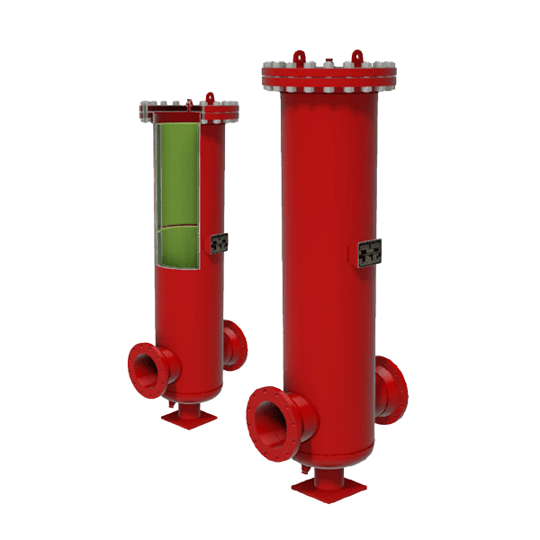
The Flo-Dyne suction stabiliser works by using a gas cushion over the pumped liquid so that we can then reduce acceleration head and pulsation by exploiting three basic properties, which each contributes to the overall elimination of pulsation and NPSH problems:
Every suction stabiliser has a gas charge which, as it is obviously more compressible than the liquid being pumped, will provide a capacitance or spring effect which in turn will absorb the pulsation created by the abrupt flow change as the pump suction valves open and close.
Flow through the suction stabiliser is slowed and rotated before leaving through the exit nozzle. By controlling the transit time and flow velocities through the equipment, entrained gases are encouraged to break out of solution and collect at the top of the stabiliser instead of passing directly into the pump inlet nozzle which reduces the quantity of entrained gas entering the pump, thereby reducing or eliminating the conditions for cavitation to happen.
The suction stabiliser acts as a mini-storage tank, the stabiliser provides a full charge of liquid when the pump valves open and allows for smooth acceleration and deceleration of the liquid in the line. By providing the tank volume close to the pump, acceleration head is eliminated and the possibility of cavitation occurring in the pump cylinders is eliminated.


 8613371530291