
mud pump that gives sufficient flowrate but not enough pressure factory

When choosing a size and type of mud pump for your drilling project, there are several factors to consider. These would include not only cost and size of pump that best fits your drilling rig, but also the diameter, depth and hole conditions you are drilling through. I know that this sounds like a lot to consider, but if you are set up the right way before the job starts, you will thank me later.
Recommended practice is to maintain a minimum of 100 to 150 feet per minute of uphole velocity for drill cuttings. Larger diameter wells for irrigation, agriculture or municipalities may violate this rule, because it may not be economically feasible to pump this much mud for the job. Uphole velocity is determined by the flow rate of the mud system, diameter of the borehole and the diameter of the drill pipe. There are many tools, including handbooks, rule of thumb, slide rule calculators and now apps on your handheld device, to calculate velocity. It is always good to remember the time it takes to get the cuttings off the bottom of the well. If you are drilling at 200 feet, then a 100-foot-per-minute velocity means that it would take two minutes to get the cuttings out of the hole. This is always a good reminder of what you are drilling through and how long ago it was that you drilled it. Ground conditions and rock formations are ever changing as you go deeper. Wouldn’t it be nice if they all remained the same?
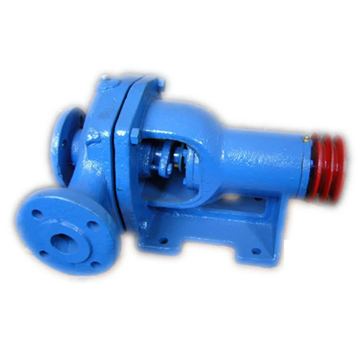
Centrifugal-style mud pumps are very popular in our industry due to their size and weight, as well as flow rate capacity for an affordable price. There are many models and brands out there, and most of them are very good value. How does a centrifugal mud pump work? The rotation of the impeller accelerates the fluid into the volute or diffuser chamber. The added energy from the acceleration increases the velocity and pressure of the fluid. These pumps are known to be very inefficient. This means that it takes more energy to increase the flow and pressure of the fluid when compared to a piston-style pump. However, you have a significant advantage in flow rates from a centrifugal pump versus a piston pump. If you are drilling deeper wells with heavier cuttings, you will be forced at some point to use a piston-style mud pump. They have much higher efficiencies in transferring the input energy into flow and pressure, therefore resulting in much higher pressure capabilities.
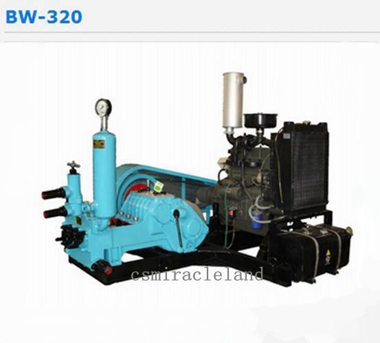
Piston-style mud pumps utilize a piston or plunger that travels back and forth in a chamber known as a cylinder. These pumps are also called “positive displacement” pumps because they literally push the fluid forward. This fluid builds up pressure and forces a spring-loaded valve to open and allow the fluid to escape into the discharge piping of the pump and then down the borehole. Since the expansion process is much smaller (almost insignificant) compared to a centrifugal pump, there is much lower energy loss. Plunger-style pumps can develop upwards of 15,000 psi for well treatments and hydraulic fracturing. Centrifugal pumps, in comparison, usually operate below 300 psi. If you are comparing most drilling pumps, centrifugal pumps operate from 60 to 125 psi and piston pumps operate around 150 to 300 psi. There are many exceptions and special applications for drilling, but these numbers should cover 80 percent of all equipment operating out there.
The restriction of putting a piston-style mud pump onto drilling rigs has always been the physical size and weight to provide adequate flow and pressure to your drilling fluid. Because of this, the industry needed a new solution to this age-old issue.
Enter Cory Miller of Centerline Manufacturing, who I recently recommended for recognition by the National Ground Water Association (NGWA) for significant contributions to the industry.
As the senior design engineer for Ingersoll-Rand’s Deephole Drilling Business Unit, I had the distinct pleasure of working with him and incorporating his Centerline Mud Pump into our drilling rig platforms.
In the late ’90s — and perhaps even earlier — Ingersoll-Rand had tried several times to develop a hydraulic-driven mud pump that would last an acceptable life- and duty-cycle for a well drilling contractor. With all of our resources and design wisdom, we were unable to solve this problem. Not only did Miller provide a solution, thus saving the size and weight of a typical gear-driven mud pump, he also provided a new offering — a mono-cylinder mud pump. This double-acting piston pump provided as much mud flow and pressure as a standard 5 X 6 duplex pump with incredible size and weight savings.
The true innovation was providing the well driller a solution for their mud pump requirements that was the right size and weight to integrate into both existing and new drilling rigs. Regardless of drill rig manufacturer and hydraulic system design, Centerline has provided a mud pump integration on hundreds of customer’s drilling rigs. Both mono-cylinder and duplex-cylinder pumps can fit nicely on the deck, across the frame or even be configured for under-deck mounting. This would not be possible with conventional mud pump designs.
Centerline stuck with their original design through all of the typical trials and tribulations that come with a new product integration. Over the course of the first several years, Miller found out that even the best of the highest quality hydraulic cylinders, valves and seals were not truly what they were represented to be. He then set off on an endeavor to bring everything in-house and began manufacturing all of his own components, including hydraulic valves. This gave him complete control over the quality of components that go into the finished product.
The second generation design for the Centerline Mud Pump is expected later this year, and I believe it will be a true game changer for this industry. It also will open up the application to many other industries that require a heavier-duty cycle for a piston pump application.
Every trenchless project needs a method to remove excavated soil from the bore. Some methods use augers, while others could even be hand excavated. But, many trenchless construction projects use slurry systems for this purpose.
A slurry mixture – or mud containing water, bentonite and other additives – is pumped down the drill string. The mud pushes out of the drilling head itself, helping to lubricate the side walls of the bore. This makes it easier for the pipe to slide through the soil. Slurry also maintains a pressure inside the bore to withstand the effects of groundwater pushing in. A positive pressure inside the bore is important to prevent tunnel collapse. Microtunneling and HDD are typical trenchless methods which use a slurry system. (For more on mud, check out Bentonite and the Use of Drilling Mud in Trenchless Projects.)
Slurry pumps supply enough pressure to push the mud through the bore, carrying spoil from the excavation back to the surface with it. From there it enters a separation unit to remove the solids before being recycled in the system. These pumps operate in harsh conditions and often require both high pressures and high flow rates.
Sizing a slurry pump correctly is a critical part of the pump selection process. This ensures that it will operate within its design parameters, avoiding premature pump failures and costly downtime.
There are a wide variety of types of pump, including reciprocating, diaphragm and centrifugal pumps. Many slurry systems use centrifugal pumps because of their robustness and performance characteristics. A centrifugal pump works by rotating an impeller which pushes the slurry through the system.
Pump capacity is primarily defined by two parameters: head pressure and flow rate. Manufacturers supply each pump with a pump curve where pressure and flow are plotted against each other. It is this curve that we use to determine whether a pump is suitable for our application.
Chemical Engineering describes a detailed process for engineers to follow when sizing a pump. The more complex the application, the more important it is to have expert help in establishing the pump design characteristics needed. Nevertheless, there are some fundamental steps that can be applied in every situation.
Dynamic head is effectively the pressure at the discharge of the pump in order to supply the energy needed to push the slurry through the system. A major factor that affects the dynamic head is changes in level from the slurry supply tank to the lowest point in the bore and back up again. The pump must overcome the forces of gravity to push the mud back out of the ground.
Another significant factor is the friction of the system. As the slurry passes through the drill pipe and back up to the surface, it encounters friction against the surface walls of the pipe. Slurry pumps must provide enough energy to overcome these forces of friction too.
Besides supplying sufficient dynamic head based on the calculations above, a slurry pump must also push the required volume of slurry through the system. This is defined in terms of flow rate. The flow rate required for a trenchless project is heavily dependent on the soil conditions and the size of the bore. Sandy soils need the lowest volume of slurry to carry the spoil to the surface in an HDD project. But, shale conditions may require up to 20 times as much. (To learn more about ground conditions, see When Ground Improvement is Needed During Trenchless Rehabilitation.)
No pump operates at 100 percent efficiency. In fact, efficiencies can range from as low as 50 percent up to over 90 percent. This means that from 10 to 50 percent of the energy you supply to the pump is not actually used to move the slurry through the system – it is lost. The better the efficiency of the pump, the lower your operating costs will be. However, efficiency is based on where on the pressure/flow curve the pump is operating.
A pump curve is essentially a graphic representation of the performance of a pump. If the head and flow rate of your application sits on or below the pump curve, then the pump is capable of performing that task. A steep curve means that it can generate a lot of head but limited flow rate. Flat pump curves represent pumps that can generate high flows but have a limited head pressure.
Pump manufacturers actually supply a series of curves for each pump that represent the pump’s performance for different diameter impellers. Efficiency curves can be overlaid on the pump performance curve to indicate where the pump is operating in its best efficiency range.
Selecting an efficient pump is important, as it saves on operating costs like electricity or generator fuel. One pump may be cheaper to buy but cost much more to run in the long term. It may be better to buy a more expensive pump up front, but one that has a good efficiency and lowers your operating costs.
Operating on the left side of the pump curve will lead to symptoms of temperature rise, noisy operation due to cavitation and vibration, which will ultimately result in low bearing and seal life and regular maintenance outages.
When analyzing pump failures, it is important to look at the whole system and not just the pump itself. Monitor and record pressure readings in the mud circulation system and check friction calculations. An error in these calculations could mean that you have the wrong pump for your service and therefore have a solution that is prone to failure.
As in most process applications using pumps, it is often not the cost of a pump repair that is the primary problem. The problem is the interruption to the project while the repair is being executed.

The policy set forth below outlines the personal data that Power Zone Equipment may collect, how Power Zone Equipment uses and safeguards that data, and with whom we may share it. This policy is intended to provide notice to individuals regarding personal data in an effort to be compliant with the data privacy laws and regulations of the jurisdictions in which Power Zone Equipment operates.
Power Zone Equipment encourages our employees, independent contractors, customers, suppliers, commercial visitors, business associates, and other interested parties to read this policy. By using our website or submitting personal data to Power Zone Equipment by any other means, you acknowledge that you understand and agree to be bound by this policy, and agree that Power Zone Equipment may collect, process, transfer, use and disclose your personal data as described in this policy.
Power Zone Equipment is committed to maintaining all reasonable precautions to ensure the privacy and security of personal data gathered by Power Zone Equipment. During your use of our website or through other communications with Power Zone Equipment, personal data may be collected and processed by Power Zone Equipment. In general, Power Zone Equipment collects personal contact information (e.g. name, company, address, telephone number and e-mail address), which you knowingly provide either by registration, requesting quotes, answering questions or otherwise for use in our commercial relationship. At times we may collect additional personal data that you voluntarily provide, including, but not limited to, job title, additional contact information, date of birth, hobbies, areas of interest, and professional affiliations.
Power Zone Equipment’s website is intended to be used by Power Zone Equipment customers, commercial visitors, business associates, and other interested parties for business purposes. Personal data collected by Power Zone Equipment through its website or by other means is used in support of our commercial relationship with you, including, but not limited to, the processing of customer orders, orders from vendors, managing accounts, learning about customers’ needs, responding to inquiries, and providing access to information. Also, in compliance with the laws and regulations of the relevant jurisdiction to support our relationship with you:
If you choose not to have your personal data used to support our customer relationship (especially direct marketing or market research), we will respect your choice. We do not sell your personal data to third parties, nor share it with third parties except as set forth in this policy. Power Zone Equipment will retain your personal data as long as you maintain a customer relationship with Power Zone Equipment and/or if you have registered to receive marketing or other communication from Power Zone Equipment, until such time as you request that we delete such personal data.
For our customers in Switzerland and the European Union (EU), please note that Power Zone Equipment is a US based company. If you use our websites or web portals or, all information, including personal information, may be transferred to Power Zone Equipment (including subcontractors that may be maintaining and/or operating our website) in the United States and elsewhere and may be transferred to third parties that may be located anywhere in the world. Although this may include recipients of information located in countries where there may be a lower level of legal protection for your personal information than in your location country, we will protect your information in accordance with requirements applicable to your information and/or location. Specifically, for data transfers out of the EU, Power Zone Equipment will utilize data transfer agreements containing the Standard Contractual Clauses. By using our websites or web portals, you unambiguously consent to the transfer of your personal information and other information to the United States and elsewhere for the purposes and uses described herein.
When you access Power Zone Equipment’s websites or web portals, we may automatically (i.e., not by registration) collect non-personal data (e.g. type of Internet browser and operating system used, domain name of the website from which you came, number of visits, average time spent on the site, pages viewed). We may use this data and share it with our worldwide affiliates and related service providers to monitor the attractiveness of our websites and improve their performance or content. In this case, processing is performed on an anonymous basis and at Power Zone Equipment’s discretion.
In addition, certain online technical applications or other interactions you have with Power Zone Equipment may require the entry of business and technical data. By providing the requested information, you are consenting to the processing and storage of such information by Power Zone Equipment. Unless Power Zone Equipment is advised that you want this information removed from Power Zone Equipment’s server, such information may be retained by Power Zone Equipment and used for future commercial communications. A request for removal of this information can be made at the contact information provided below. Power Zone Equipment will take all reasonable precautions to assure that no such information will be provided or divulged to other third parties, except, if applicable, those third parties performing site hosting, maintenance, and related site service activities.
Power Zone Equipment will not knowingly collect personal data from children under the age of 18. Power Zone Equipment’s website(s) is not intended for individuals under 18 years of age
Power Zone Equipment will use personal data only in ways that are compatible with the purposes for which it was collected or subsequently authorized by you. While Power Zone Equipment will take reasonable steps to ensure that personal data is relevant to its intended use, accurate, complete, and current, Power Zone Equipment is also relying upon each individual to assist in providing accurate updates of his or her personal data.
Power Zone Equipment website(s) may contain “links” to websites owned and operated by third parties. By accessing these links, which are provided for your convenience, you will leave our site and will be subject to the privacy practices of the other website. This policy does not apply to any personal information you provide to unrelated third parties.
In general, Power Zone Equipment will only retain personal data for as long as needed for the specific purpose of processing and in accordance with Power Zone Equipment’s records management policy, or as otherwise required by the laws and regulations of a particular jurisdiction. For example, data will be retained during the time period that you are authorized to use Power Zone Equipment website(s), including any Power Zone Equipment tools accessible through our website(s). Upon termination of such authorization, your personal data related to use of Power Zone Equipment website(s) will be removed.
Upon request, Power Zone Equipment will grant individuals reasonable access to personal data that it holds about them. In addition, Power Zone Equipment will take reasonable steps to permit individuals to correct, amend, or delete information that is demonstrated to be inaccurate or incomplete. Power Zone Equipment also relies upon each individual to assist in providing accurate updates of his or her personal data. In order to access, correct, amend, or delete the personal data Power Zone Equipment holds about an individual, the individual should contact the following:
To the extent required by applicable law, Power Zone Equipment will grant individuals reasonable access to personal data that Power Zone Equipment holds about them and will take reasonable steps to permit such individuals to correct, amend, or delete information that Power Zone Equipment holds about them. Power Zone Equipment also relies upon each individual to assist in providing accurate updates of his or her personal data. In order to access, correct, amend, or delete the personal data Power Zone Equipment holds about an individual, the individual should contact his or her Power Zone Equipment commercial contact or contact us at the following email address:sales@powerzone.com.
Power Zone Equipment reserves the right to modify this policy from time to time in order that it accurately reflects the legal and regulatory environment and our data collection principles. When material changes are made to this policy, Power Zone Equipment will post the revised policy on our website.

Industrial pumps are essential devices required in every phase of oil and gas operations. Basically, they help transfer process fluids from one point to another.
For example, a pump can be used to transfer crude oil from a storage tank to a pipeline and mud pumps are used to circulate drilling mud into the annulus of a drill bit and back to a storage tank for re-purification.
In oil and gas operations, process fluids can range from easy to difficult. Depending on the nature of the substance you want to transfer and your required flow rate, you’ll need a suitable pump for your needs.
Various types of industrial pumps are utilized for fluid transfer in the oil and gas industry. Pumps used in O&G can be classified based on their design and construction and generally fall into 6 major categories:
Centrifugal pumps are the most common types of pumps used in the oil and gas industry. Centrifugal pumps use centrifugal force through the rotation of the pump impeller to draw fluid into the intake of the pump and force it through the discharge section via centrifugal force. The flow through the pump is controlled by discharge flow control valves.
Single stage centrifugal pumps are primarily used for transferring low-viscosity fluids that require high flow rates. They are typically used as part of a larger pump network comprising other centrifugal pumps like horizontal multistage pump units for crude oil shipping or water injection pumps used in secondary oil and gas recovery.
Plunger pumps are some of the most ubiquitous industrial pumps in the oil and gas industry. Plunger pumps use the reciprocating motion of plungers and pistons to pressurize fluid in an enclosed cylinder to a piping system. Plunger pumps are considered constant flow pumps since at a given speed, the flow rate is constant despite the system pressure. A relief valve is an essential part of any plunger pump discharge piping system to prevent overpressuring of the pump and piping system.
Plunger pumps require more frequent maintenance than centrifugal pumps due to the design of the moving parts. They also have a noisier operation than centrifugal pumps.
A progressive cavity pump is a type of positive displacement pump and is also known as an eccentric screw pump or cavity pump. It transfers fluid by means of the progress, through the pump, of a sequence of small, fixed shape, discrete cavities, as its rotor is turned. Progressive cavity pumps are used in high viscosity applications or if blending the of the pumped fluid is not desired.
Progressive cavity pumps are also considered constant flow pumps since at a given speed, the flow rate is relatively constant despite the system pressure. Flow slippage is normal at higher pressures. A relief valve is an essential part of any progressive cavity pump discharge piping system to prevent overpressuring of the pump and piping system.
Diaphragm pumps are one of the most versatile types of oil and gas pumps in the industry and transfer fluid through positive displacement with a valve and diaphragm. The working principle of this pump is that a decrease in volume causes an increase in pressure in a vacuum and vice versa.
Diaphragm pumps are suitable for high-volume fluid transfer operations in oil refineries. They also require much less maintenance than positive displacement pumps due to their fewer moving parts and less friction during operation and are available in compact designs.
On the downside, diaphragm pumps are susceptible to ‘winks’ – low-pressure conditions inside the system that slow down pumping operations. Fortunately, winks can be rectified by using a back-pressure regulator. For the same reason, they are not suitable for continuous or long-distance pumping operations as they generally don’t meet the high-pressure conditions required.
A gear pump uses the meshing of gears to pump fluid by displacement. Gear pumps are one of the most common types of positive displacement pumps for transferring industrial fluids.
Gear pumps are also widely used for chemical transfer applications for high viscosity fluids. There are two main variations: external gear pumps which use two external spur gears or timing gears that drive the internal gear set. The internal gears do not touch, so non-lubricating fluids can be pumped with external gear pumps. Internal gear pumps use a shaft driven drive gear to drive the internal mating gear. Gear pumps are positive displacement (or fixed displacement), meaning they pump a constant amount of fluid for each revolution.
Since the pumped fluid passes between the close gear tolerances, gear pumps are normally used for clean fluids. A relief valve is an essential component in the discharge piping system to protect the pump and piping from over pressurizing.
A metering pump moves a precise volume of liquid in a specified time period providing an accurate flow rate. Delivery of fluids in precise adjustable flow rates is sometimes called metering. The term “metering pump” is based on the application or use rather than the exact kind of pump used. Most metering pumps are simplex reciprocating pumps with a packed plunger or diaphragm liquid end. The diaphragm liquid end is preferred since the pumped fluid is sealed inside the diaphragm. No pumped liquid leaks to the atmosphere.

This website is using a security service to protect itself from online attacks. The action you just performed triggered the security solution. There are several actions that could trigger this block including submitting a certain word or phrase, a SQL command or malformed data.
I am often asked to visit plant sites to consult on problems regarding inadequate flow rates in two-pump systems. These plants are usually more than 10 years old, and the commissioning operators and engineers are no longer present. Plant output requirements have increased, and/or the equipment is simply old and less efficient. Either way, the desired outcome is to obtain more flow through the system.
In a typical scenario, someone observes there is an additional installed pump and decides the solution is to simply start and operate the second pump. To an untrained person who sees two pumps installed in the same system, it seems logical that operating the second pump in parallel will increase the flow. This may work in some instances but often does not. When the system is not designed for two (or more) pumps to operate at the same time (in parallel), it will not take long for both pumps to experience issues.
Two pumps set up to run individually and/or in parallel. In other words, pumps can run in parallel or separately, covering a wide range of expected flows.
To find the solution to the problem, the first thing I ask for is the system curve. The curve is often not available, so I work with plant personnel to calculate and develop the system curve. Once we overlay the system curve on the pump curves, the issue and possible solutions become readily apparent.
In many cases, the system designer may have designed the system to have one pump do all of the required work (100 percent duty pump) with a second pump (also known as the redundant pump, installed spare, 100 percent spare or backup pump) ready for operation so the first pump can be removed from service without disturbing the production process. The pumps and their associated motors and controllers are each designed for 100 percent duty.
The intersection of the single pump curve and the system curve should be near the best efficiency point (BEP) for the pump. In these types of cases, the piping system is not designed for both pumps to operate at the same time. The pipe size is typically too small to efficiently handle the higher flows and presents a huge friction loss if both pumps are operated. Another way to think of this situation is the system curve is steep—not flat—for two-pump operation.
If the system is designed for both pumps to operate at the same time, then the system curve will, by design, be flatter overall and present less friction. You can also think of undesired friction as wasted horsepower, which translates to higher electrical costs.
This column is not meant to explain in detail why one curve is steep and the other is flat. The important point to note is the steeper curves represent more friction loss as you attempt to pump more flow through the pipe. For this article, it is sufficient to say that if the system is designed for parallel pumping, the system curve will tend to be flatter.
Figure 1 depicts a properly designed system for parallel pump operations. With one pump operating (Intersection Point 1), the system curve remains relatively flat, and flow is X with corresponding head Y.
When the second pump is started (Intersection Point 2), the friction presented by the higher flows yields a slightly steeper system curve. While the flow will be more than X, please note that it will not attain magnitude 2X.
Figure 2 shows that if one of the pumps is an installed spare and both pumps are operated at the same time, then the additional flow is too much for the given pipe diameter, and the result is a high friction loss.
Looking at Operating Point 2, you can see that starting the second pump has yielded little additional flow. It could be in the range of X flow plus 10 percent, but in many cases it is even worse. This is why starting the second pump can actually kill both pumps.
In these situations, there will always be a strong pump and a weak pump. Even if the pumps were designed and manufactured to be identical, there is always some nuance in one of the pumps and in the system that will prevent the pumps from being identical.
The stronger pump will attempt to take the full load (as presented by the system). The stronger pump will run far right on its curve (a condition called runout) and have issues with vibration and cavitation (net positive suction head [NPSH] and flow angle incidence recirculation) that will manifest as damaged impellers as well as short-lived bearings and mechanical seals. At the same time, the weak pump will run at low to no flow and have similar issues because it is operating at the far left side of the curve. It is not uncommon for the stronger pump to develop sufficient pressure to close the discharge check valve on the weaker pump, consequently forcing it to operate at a shutoff head (zero flow rate).
Figure 3 shows the operation of Pump 1 (Intersection Point 1) and the subsequent parallel operation of Pump 2. A common misunderstanding is that if you start the second pump, the flow rate will double to Intersection Point 2. In reality, the actual operating point will be at Intersection Point 3. In a centrifugal pump system, the pump will always operate where the system curve dictates.
Pumps in a system that is not designed for parallel operation should not be operated at the same time except for brief intervals during switching operations. To do otherwise is likely to prematurely damage both pumps.
Often, a good system design is to have pumps in parallel because they can provide flexibility to match the flow to the load. This setup is also more reliable because it provides standby protection for a relatively high percentage of the full load in the event of one pump loss.
Different pump designs/models can operate together in parallel, but it is important that they have an identical shutoff head and similar specific speeds.
If the system is designed for parallel pumps, determine which pump is the stronger one by running one at a time and measuring the head at various flows. As a general rule, always start the weaker pump first.
You can overcome some of the mismatches in pump and system designs by using variable speed drives and carefully monitoring where each pump is on the curve, changing speeds as required to keep the load balanced.
When running one pump for small loads and then starting the second pump to pick up larger loads, do not let the first pump run out on its curve too far before the second pump is started. The first pump may be cavitating for some time before the second pump picks up. I see this happen often on systems designed to operate automatically. The designer often overlooks the NPSH margins at the right side of the curve.
Whether the pumps are in parallel or it is just two pumps in a one-pump system, I always recommend installing hour meters to track the operating hours. I have witnessed many mistakes resulting from decisions based on someone"s memory or record-keeping habits. Hour meters are inexpensive insurance. (Do you know when to change the oil in the pump?)
In a parallel pump system, whichever pump is started first must be capable of covering the full load presented by the system curve without overloading the driver or running out on its own curve.

Annular area drives the speed at which the fluid and suspended drilled material will travel up the hole at given flow rate. Smaller the clearance between drill string components and borehole – faster the fluid will flow across this particular interval. Generally, it is recommended to keep the annular fluid velocity (AV) above 150 ft / min (46 m / min). Desired AVs could be controlled by changes of mud circulation rate, drill string component sizes and wellbore internal diameter. This is why underreaming is one of the last resorts in ERD – elevated flow rates are required to drill larger open hole. This could be a problem if the rig has low-rated high pressure system.
In most cases, AVs across BHA components are quite high and cuttings are “flushed away” in seconds. Drill pipe normally has smaller OD than BHA components or it is situated across large ID casing / liner string. If annular velocity is insufficient, cuttings accumulation is likely to form in high angle sections and at geometry changes such as formation washouts and immediately above liner tops. In addition, accelerated barite sagging is expected in areas of low annular velocity.
Here is the real-life example: one of our clients wanted to drill 6-⅛” hole section in a well with 3 liners in place: 11-¼”, 9-⅝” and 7-⅝” (not tied-back due to ECD constraints). Annular velocity inside 11-¾” liner and above was found to be insufficient to deliver adequate hole cleaning for given flow rates, dropping to as low as 15 m/min across 13-⅜” casing interval. Drill string and mud rheology optimization allowed us to install 9-⅝” tie-back and keep actual ECD below perceived fracture gradient.

The “pond” is actually a man made dam which covers an area of about 40ha and has rockfill embankments of up to 53m high along the southern side that forms the impoundment. It initially constructed in 1959 to act as a tailings pond to take the bauxite residue (red mud) from the Ewarton Plant situated about 5km away and 300m lower. The red mud was pumped as a slurry comprising about 20% solids to the pond over a period of about 32 years up to 1991 when the pond was replaced by the Charlemount Mud Stacking and Drying Facility. During this period the pond embankments (referred to as dams), were raised up to 7 times providing a final crest elevation of 472m. The pond was however never filled to its final design capacity and the mud beach level remained at about 469m and the central area about 458m leaving a concave depression which held about 1.4mil m3 of water with elevated pH and some caustic content.
The remediation plan for the pond includes the removal of the ponded water and then the regrading of the mud surface to be free draining so that it can be stabilised and vegetated. About 500,000 m3 of mud will need to be moved over a distance of up to 1km in order to create the required profile. Due to the very soft nature of the surface muds (shear strength of less than 3kPa) its bearing capacity is less than 20kPa hence it is not accessible using even modified earthworks equipment. In addition, the muds are thyrotrophic and under any vibration or shear loading, rapidly liquefy resulting in significant reduction in shear strength and loss of bearing capacity. Using conventional earthmoving equipment would therefore require extensive “floating” haul roads with a high risk of machinery getting stuck or entire plant loss and risk to personnel. It was therefore decided to investigate the possibility of pumping the in-situ red mud.
A mud pumping trial was undertaken to assess the feasibility of using this technique to do the bulk mud moving. Pumping red mud is not unusual and the muds were initially pumped up to Mt Rosser Pond. However, the muds are usually pumped at a solids content of 30% or less. Once deposited, they can take years to reconsolidate and firm up sufficiently to allow access for light earthworks and agricultural plant.
In addition to the mud pumping, the trial included infilling three small scale geotubes to assess their performance as these may be needed as part of the regrading works.
The main aim of the pump trial was to determine if the muds could be pumped in their insitu state, and if not, what amount of water is required and how the variations in water content affect pump rates.
The mud pumping trial was undertaken using a 4” EDDY Pump. This pump was recommended due to its ability to handle variable solids and robust operating mechanism. The pump unit incorporated a hydraulic drive and cutter head. The unit was mounted onto the boom of a JCB 220 excavator which also supplied the hydraulic feed to power the pump for the required range of 30-40 GPM at 3,500 to 4,000 psi (2428MPa). The cutter head was powered by a standalone hydraulic power unit capable of providing the required 30gpm at 200psi (1.9 l/s at 13.8MPa). If mounted on a 30-ton excavator with a System 14 hydraulic system and dual auxiliary feeds to the boom, all necessary hydraulic power for the pump and cutter head can be supplied by the excavator. This equipment was however not available at the time in Jamaica.
In addition to the pump mounted on the excavator a Long Reach excavator (CAT 325) was used to move muds towards the cutter head but also to loosen up the muds and mix in additional water to facilitate pumping. Water was added by pumping it directly from the pond using a 3” diesel water pump.
Prior to pumping the muds, the mud pump would operate in recirculation mode in order to prime the pump. When in recirculation (re-circ) mode, the material pumped would be diverted to a short discharge pipe mounted on the pump directed back parallel to the cutter head. This action would help agitate and stir the muds.
The geotubes for the trials were 6m long and 1m high (filled) and were supplied by Tencate. The tubes were made from a woven polyester – GT1000M and had a central top filling point. A set of small bags with a polymer test set was also provided but this was not tried during this occasion.
A geotechnical soils investigation was undertaken on the muds within Mt Rosser pond in 2004. It showed the material to be predominantly clayey silt with approximately 13% sand, 29% clay and 58% silt using conventional sieve analysis and hydrometer. Atterberg limits indicate that the material is an intermediate to high plasticity clay. The muds do however vary across the lake and also vertically. This is mainly as a consequence of the deposition process and discharge location. Close to the discharge location the courser materials would settle out first and the finer materials would disperse furthest and to the opposite end of the pond. The results are presented in figure 4.1.
Earlier this year, additional mud samples were tested as it was evident that standard soil mechanics tests did not provide an accurate assessment of this fine material. This was particularly evident in tests done with dry sieving which shows the material as well-graded sand (see results for samples 5300, 5301, 5302 on figure 4.2). When dispersed in water, even with an agent, the ‘yield-pseudo-plastic’ rheology of the muds appeared to affect the hydrometer results with large variations between tests (see results of samples PFT4&5 taken during mud pumping trials on figure 4.2).
The additional testing comprised of undertaking gradings using a Laser Particle Analyzer. The results indicated that the muds are predominantly Silt although the silt % varied from 30% to 80% with the material being either more sandy or more clayey (up to 15% clay). See results of samples ending in “L” on figure 4.2 below.
Moisture content tests on the muds taken from within the mud pond but below the ponded water ranged from 100% to 150% (50% to 40% solids). The muds at the pump test location were 137% (42% solids).
Shear strength was generally very low ranging from 1kPa to 6kPa increasing with depth. Dynamic probes previously undertaken indicated that the muds are “very soft” to 5m increasing in strength slightly to “soft” at a depth of 9m after which they increase to firm becoming stiff.
The pH of the muds ranged from 10.3 to 11.7, (ave 11.2). Previous testing indicated that the surface muds have the lower pH although once through the crust, the pH tends to be higher. When doing the trials, the muds up to a depth of about 2.5m was intermixed, hence any stratification in pH could not be determined.
Initially, pumping was problematic mainly due to the excavator being underpowered. This was diagnosed as a hydraulic pump problem and the excavator was replaced. The cutter head (which also acts to protect the intake) tended to blind with mud (Photo 5.1) and was also not providing enough agitation to liquefy the muds. This was partly resolved by adding “stirrers” (2 steel loops welded either side) to the rotating cutter head and also a “comb” (Photo 5.2) to keep the gaps within the cutter head open.
Mud pumping rates varied from 21 l/s to 52 l/s (332 – 824gpm) and it was clearly visible that the more liquid the muds were the higher the pump rate was. Samples were taken at different discharge rates and moisture content and percent solids determined by laboratory testing. The results are plotted in Figure 5.1 and although scattered, do give an indication of the effects of solids content on flow rates. The natural moisture content of the muds (insitu) at the test location was 137%, or 42% solids. This is shown in Figure 5.1 as a vertical line. Pumping muds close to the percent solids was achieved although flow rates were low.
As mentioned previously, the long reach excavator was used to loosen up the muds. Water was pumped from the pond using a 3” pump into the excavation and the long reach would then work the muds to mix the water in. The mud pump would then be used in recirculation mode to further mix the muds into a more consistent state. Even with this mixing and agitation, the water tended to concentrate on the surface. This aided the initial process of priming the pump and once primed thicker muds at 1m to 2m below the surface could be pumped. However, it was found that the deeper muds tended to be lumpy and this would significantly reduce or stop the flow requiring the pump to be lifted into thinner muds or having to go back into re-circ mode or having to fully re-prime. The pump discharge was therefore very inconsistent as the suction intake position constantly needed adjustment in an attempt to get adequate discharge but also pump the thickest muds possible.
Discharge of the pumped muds was through 30m of flexible hose then 60m of 4” HDPE pipe which had an internal diameter of about 87mm (3.5”). The muds were discharged onto the original mud beach which lies at a gradient of about 9%. On deposition the muds slowly flowed down gradient. At times the flow would stop and the muds would build up then flow again in a wave motion. The natural angle of repose would therefore be a few degrees less than this – probably 5% to 6%.
Although the muds have very low shear strength, and on agitation liquefy, the sides of the excavation had sufficient strength to stand about 2m near vertical. Even overnight, there was limited slumping and the bank could be undermined by about 0.5m with the cutter head/agitator before collapsing.
On termination of pumping, in order to flush the pipeline, thin watery muds were pumped until the line was clear. A “T” valve system was then used to connect the 3” water pump line and this was then used to flush the pipe with water.
Three geotubes (1m x 6m) were filled with red muds pumped using the 4” Eddy pump. Fill rates were about 30 to 40l/s although it was difficult to assess as the flow and mud consistence was not visible.
Tube 1 was filled initially with more runny mud and then thicker muds as the pump operator got a better feel for conditions. The tube was filled until firm. The second tube was filled with thicker muds and filling continued until the tube was taut. These two tubes were positioned on the sloping beach in order to form a small “U” impoundment area that would later be filled with pumped muds. Although the area was prepared, the sloping ground caused the first tube to rotate through about 20 degrees. The tube was staked and the downslope side backfilled. A more defined bed was created for the second tube and the same rotational issue was limited. The two filled tubes with the ponded mud are shown in Photos 5.7 and 5.8. Other than a small leak at the contact between the two geotubes, the ponding of the muds was successful.
The third tube was positioned on level ground. It was filled with medium runny (but consistent thickness) muds and was filled until the tube was taut.
In all three cases, there was very little mud loss or seepage from the tubes. When stood on, some red water would squeeze out around the pressure area. Once filled taut, the entire bag would have small red water droplets form on the outside (visible in Photo 5.11) , but the seepage was in general nominal.
The tubes have been monitored and the most recent photo’s taken on 10 October 2011 (6 weeks after filling) show how the tubes have reduced in volume due to the dewatering of the contained muds. Volume loss is estimated to be around 30%. The anticipated moisture content would therefore be about 90% and the solids around 53%.
The muds pumped into the trial pond behind the geotubes were medium thick to thick, probably in the order of 37 – 40% solids. After 6 weeks the mud has not only firmed-up but had dried out significantly with wide and deep surface cracks as are evident in Photo 5.14 and 5.15.
The muds can be pumped at close to their insitu moisture content and most likely at their in-situ moisture content if they were agitated more and the pipeline system was designed to reduce friction losses.
Be able to access the mud surface and move around efficiently and safely. The suggestion is to have the pump mounted on a pontoon that is positioned using high strength rope (dynema) or steel cable. The pump system should be remotely controlled as this would limit regular movement of personnel on the muds.
Have sufficient power and volume capacity to pump the muds at close to or at in-situ moisture content and discharge them about 1000m through a flexible pipeline.
It was also evident from the trials that the muds do not slump and flow readily. It will therefore be necessary to have an amphibious excavator to loosen up the muds in the area around the pump head. This weakened and more liquid mud would also aid the movement of the pump pontoon. To also limit the amount of movement the pontoon will need to do, the amphibious excavator could also move muds towards the pump location.
Using the capacity of the 4” mud pump, mud moving would take about 1.5 to 2 years, the pump will however need to be more suited to the task. A target period of 1 year however seems reasonable. However, prior to this, equipment will need to be procured and imported into Jamaica. The 6 and 10 inch Excavator Dredge Pump Attachments are also being considered as an option for higher GMP and a more aggressive completion timeline. A preliminary programme is as follows:

The 2,200-hp mud pump for offshore applications is a single-acting reciprocating triplex mud pump designed for high fluid flow rates, even at low operating speeds, and with a long stroke design. These features reduce the number of load reversals in critical components and increase the life of fluid end parts.
The pump’s critical components are strategically placed to make maintenance and inspection far easier and safer. The two-piece, quick-release piston rod lets you remove the piston without disturbing the liner, minimizing downtime when you’re replacing fluid parts.

Plumbing may be defined as the practice, materials, and fixtures used in installing, maintaining, and altering piping, fixtures, appliances, and appurtenances in connection with sanitary or storm drainage facilities, a venting system, and public or private water supply systems. Plumbing does not include drilling water wells; installing water softening equipment; or manufacturing or selling plumbing fixtures, appliances, equipment, or hardware. A plumbing system consists of three parts: an adequate potable water supply system; a safe, adequate drainage system; and ample fixtures and equipment.
The housing inspector’s prime concern while inspecting plumbing is to ensure the provision of a safe water supply system, an adequate drainage system, and ample and proper fixtures and equipment that do not contaminate water. The inspector must make sure that the system moves waste safely from the home and protects the occupants from backup of waste and dangerous gases. This chapter covers the major features of a residential plumbing system and the basic plumbing terms and principles the inspector must know and understand to identify housing code violations that involve plumbing. It will also assist in identifying the more complicated defects that the inspector should refer to the appropriate agencies. This chapter is not a plumbing code, but should provide a base of knowledge sufficient to evaluate household systems.
It is, therefore, very important that the housing inspector be completely familiar with all elements of these systems so that inadequacies of the structure’s plumbing and other code violations will be recognized. To aid the inspector in understanding the plumbing system, a schematic of a home plumbing system is shown in
The piping of a house service line should be as short as possible. Elbows and bends should be kept to a minimum because they reduce water pressure and, therefore, the supply of water to fixtures in the house. The house service line also should be protected from freezing. Four feet of soil is a commonly accepted depth to bury the line to prevent freezing. This depth varies, however, across the country from north to south. The local or state plumbing code should be consulted for recommended depths. The minimum service line size should be ¾ inch. The minimum water supply pressure should be 40 pounds per square inch (psi), no cement or concrete joints should be allowed, no glue joints between different types of plastic should be allowed, and no female threaded PVC fittings should be used.
Corporation stop—The corporation stop is connected to the water main. This connection is usually made of brass and can be connected to the main with a special tool without shutting off the municipal supply. The valve incorporated in the corporation stop permits the pressure to be maintained in the main while the service to the building is completed.
The water meter is a device used to measure the amount of water used in the house. It is usually the property of the water provider and is a very delicate instrument that should not be abused. In cold climates, the water meter is often inside the home to keep it from freezing. When the meter is located inside the home, the company providing the water must make appointments to read the meter, which often results in higher water costs unless the meter is equipped with a signal that can be observed from the outside. The water meter is not shown in
Because the electric system is sometimes grounded to an older home’s water line, a grounding loop device should be installed around the meter. Many meters come with a yoke that maintains electrical continuity even though the meter is removed.
The hot and cold water main lines are usually hung from the basement ceiling or in the crawl space of the home and are attached to the water meter and hot water tank on one side and the fixture supply risers on the other. These pipes should be installed neatly and should be supported by pipe hangers or straps of sufficient strength and number to prevent sagging. Older homes that have copper pipe with soldered pipes can pose a lead poisoning risk, particularly to children. In 1986, Congress banned lead solder containing greater than 0.2% lead and restricted the lead content of faucets, pipes, and other plumbing materials to no more than 8%. The water should be tested to determine the presence or level of lead in the water. Until such tests can be conducted, the water should be run for about 2 minutes in the morning to flush any such material from the line. Hot and cold water lines should be approximately 6 inches apart unless the hot water line is insulated. This is to ensure that the cold water line does not pick up heat from the hot water line [2].
The fixture risers start at the basement main and rise vertically to the fixtures on the upper floors. In a one-family dwelling, riser branches will usually proceed from the main riser to each fixture grouping. In any event, the fixture risers should not depend on the branch risers for support, but should be supported with a pipe bracket.
The size of basement mains and risers depends on the number of fixtures supplied. However, a ¾-inch pipe is usually the minimum size used. This allows for deposits on the pipe due to hardness in the water and will usually give satisfactory volume and pressure.
Care must be taken when choosing the piping materials. Some state and local plumbing codes prohibit using some of the materials listed below in water distribution systems.
Polyvinyl Chloride (PVC). PVC is used to make plastic pipe. PVC piping has several applications in and around homes such as in underground sprinkler systems, piping for swimming pool pumping systems, and low-pressure drain systems PVC piping is also used for water service between the meter and building [3]. PVC, or polyvinyl chloride, is one of the most commonly used materials in the marketplace. It is in packaging, construction and automotive material, toys, and medical equipment.
Chlorinated PVC. CPVC is a slightly yellow plastic pipe used inside homes. It has a long service life, but is not quite as tough as copper. Some areas with corrosive water will benefit by using chlorinated PVC piping. CPVC piping is designed and recommended for use in hot and cold potable water distribution systems [4].
Copper lasts a long time, is durable, and connects well to valves. It should not be installed if the water has a pH of 6.5 or less. Most public utilities supply water at a pH between 7.2 and 8.0. Many utilities that have source water with a pH below 6.5 treat the water to raise the pH. Private well water systems often have a pH below 6.5. When this is the case, installing a treatment system to make the water less acidic is a good idea [5].
Galvanized Steel. Galvanized pipe corrodes rather easily. The typical life of this piping is about 40 years. One of the primary problems with galvanized steel is that, in saturated water, the pipe will become severely restricted by corrosion that eventually fills the pipe completely. Another problem is that the mismatch of metals between the brass valves and the steel results in corrosion. Whenever steel pipe meets copper or brass, the steel pipe will rapidly corrode. Dielectric unions can be used between copper and steel pipes; however, these unions will close off flow in a short time. The problem with dielectric unions is that they break the grounding effect if a live electrical wire comes in contact with a pipe. Some cities require the two pipes to be bonded electrically to maintain the safety of grounded pipes.
PEX. PEX is an acronym for a cross-formulated polyethylene. “PE” refers to the raw material used to make PEX (polyethylene), and “X” refers to the cross-linking of the polyethylene across its molecular chains. The molecular chains are linked into a three-dimensional network that makes PEX remarkably durable within a wide range of temperatures, pressures, and chemicals [6].
Kitec. Kitec is a multipurpose pressure pipe that uniquely unites the advantages of both metal and plastic. It is made of an aluminum tube laminated to interior and exterior layers of plastic. Kitec provides a composite piping system for a wide range of applications, often beyond the scope of metal or plastic alone. Unlike copper and steel materials, Kitec is noncorroding and resists most acids, salt solutions, alkalis, fats, and oils.
Poly. Poly pipe is a soft plastic pipe that comes in coils and is used for cold water. It can crack with age or wear through from rocks. Other weak points can be the stainless steel clamps or galvanized couplings.
Polybutylene [Discontinued]. Polybutylene pipe is a soft plastic pipe. This material is no longer recommended because of early chemical breakdown. Individuals with a house, mobile home, or other structure that has polybutylene piping with acetal plastic fittings may be eligible for financial relief if they have replaced that plumbing system. For claims information, call 1-800-392-7591 or go to www.pbpipe.comExternal.
In the United States, more than 112,000 people enter a hospital emergency room each year with scald burns. Of these, 6,700 (6%), have to be hospitalized. Almost 3,000 of these scald burns come from tap water in the home. The three high risk groups are children under the age of 5 years, the handicapped, and adults over the age of 65 years. It only takes 1 second to get a serious third-degree burn from water that is 156ºF (69ºC). Tap water is too hot if instant coffee granules melt in it.
Young children, some handicapped individuals, and elderly people are particularly vulnerable to tap water burns. Children cannot always tell the hot water faucets from the cold water faucets. Children have delicate skin and often cannot get out of hot water quickly, so they suffer hot water burns most frequently. Elderly and handicapped persons are less agile and more prone to falls in the bath tub. They also may have diseases, such as diabetes, that make them unable to feel heat in some regions of the body, such as the hands and feet. Third-degree burns can occur quickly—in 1 second at 156ºF (69ºC), in 2 seconds at 149ºF (65ºC), in 5 seconds at 140ºF (60ºC), and in 15 seconds at 133ºF (56ºC).
A tap-water temperature of 120ºF–130ºF (49ºC–54ºC) is hot enough for washing clothes, bedding, and dishes. Even at 130ºF (54ºC), water takes only a few minutes of constant contact to produce a third-degree burn. Few people bathe at temperatures above 110ºF (43ºC), nor should they. Water heater thermostats should be set at about 120ºF (49ºC) for safety and to save 18% of the energy used at 140ºF (60ºC). Antiscald devices for faucets and showerheads to regulate water temperature can help prevent burns. A plumber should install and calibrate these devices. Most hot water tank installations now require an expansion tank to reduce pressure fluctuations and a heat trap to keep hot water from escaping up pipes.
It is essential that valves be used in a water system to allow the system to be controlled in a safe and efficient manner. The number, type, and size of valves required will depend on the size and complexity of the system. Most valves can be purchased in sizes and types to match the pipe sizes used in water system installations. Listed below are some of the more commonly encountered valves with a description of their basic functions.
Shutoff Valves. Shutoff valves should be installed between the pump and the pressure tank and between the pressure tank and service entry to a building. Globe, gate, and ball valves are common shutoff valves. Gate and ball valves cause less friction loss than do globe valves; ball valves last longer and leak less than do gate valves. Shutoff valves allow servicing of parts of the system without draining the entire system.
Flow-control Valves. Flow-control valves provide uniform flow at varying pressures. They are sometimes needed to regulate or limit the use of water because of limited water flow from low-yielding wells or an inadequate pumping system. They also may be needed with some treatment equipment. These valves are often used to limit flow to a fixture. Orifices, mechanical valves, or diaphragm valves are used to restrict the flow to any one service line or complete system and to assure a minimum flow rate to all outlets.
Relief Valves. Relief valves permit water or air to escape from the system to relieve excess pressure. They are spring-controlled and are usually adjustable to relieve varying pressures, generally above 60 psi. Relief valves should be installed in systems that may develop pressures exceeding the rated limits of the pressure tank or distribution system. Positive displacement and submersible pumps and water heaters can develop these excessive pressures. The relief valve should be installed between the pump and the first shutoff valve and must be capable of discharging the flow rate of the pump. A combined pressure and temperature relief valve is needed on all water heaters. Combination pressure and vacuum relief valves also should be installed to prevent vacuum damage to the system.
Pressure-reducing Valves. A pressure-reducing v


 8613371530291