
mud pump that gives sufficient flowrate but not enough pressure in stock

When choosing a size and type of mud pump for your drilling project, there are several factors to consider. These would include not only cost and size of pump that best fits your drilling rig, but also the diameter, depth and hole conditions you are drilling through. I know that this sounds like a lot to consider, but if you are set up the right way before the job starts, you will thank me later.
Recommended practice is to maintain a minimum of 100 to 150 feet per minute of uphole velocity for drill cuttings. Larger diameter wells for irrigation, agriculture or municipalities may violate this rule, because it may not be economically feasible to pump this much mud for the job. Uphole velocity is determined by the flow rate of the mud system, diameter of the borehole and the diameter of the drill pipe. There are many tools, including handbooks, rule of thumb, slide rule calculators and now apps on your handheld device, to calculate velocity. It is always good to remember the time it takes to get the cuttings off the bottom of the well. If you are drilling at 200 feet, then a 100-foot-per-minute velocity means that it would take two minutes to get the cuttings out of the hole. This is always a good reminder of what you are drilling through and how long ago it was that you drilled it. Ground conditions and rock formations are ever changing as you go deeper. Wouldn’t it be nice if they all remained the same?
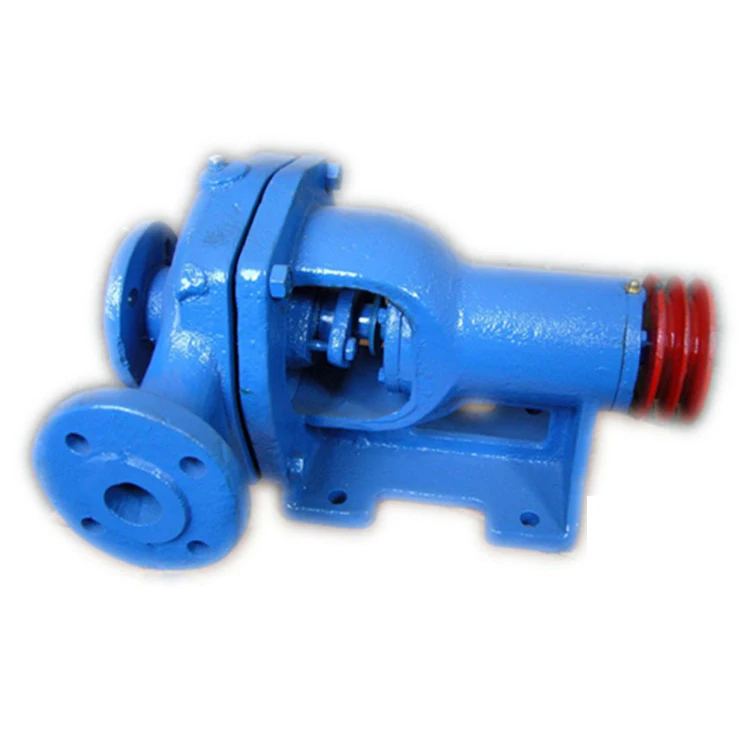
Centrifugal-style mud pumps are very popular in our industry due to their size and weight, as well as flow rate capacity for an affordable price. There are many models and brands out there, and most of them are very good value. How does a centrifugal mud pump work? The rotation of the impeller accelerates the fluid into the volute or diffuser chamber. The added energy from the acceleration increases the velocity and pressure of the fluid. These pumps are known to be very inefficient. This means that it takes more energy to increase the flow and pressure of the fluid when compared to a piston-style pump. However, you have a significant advantage in flow rates from a centrifugal pump versus a piston pump. If you are drilling deeper wells with heavier cuttings, you will be forced at some point to use a piston-style mud pump. They have much higher efficiencies in transferring the input energy into flow and pressure, therefore resulting in much higher pressure capabilities.
Piston-style mud pumps utilize a piston or plunger that travels back and forth in a chamber known as a cylinder. These pumps are also called “positive displacement” pumps because they literally push the fluid forward. This fluid builds up pressure and forces a spring-loaded valve to open and allow the fluid to escape into the discharge piping of the pump and then down the borehole. Since the expansion process is much smaller (almost insignificant) compared to a centrifugal pump, there is much lower energy loss. Plunger-style pumps can develop upwards of 15,000 psi for well treatments and hydraulic fracturing. Centrifugal pumps, in comparison, usually operate below 300 psi. If you are comparing most drilling pumps, centrifugal pumps operate from 60 to 125 psi and piston pumps operate around 150 to 300 psi. There are many exceptions and special applications for drilling, but these numbers should cover 80 percent of all equipment operating out there.
The restriction of putting a piston-style mud pump onto drilling rigs has always been the physical size and weight to provide adequate flow and pressure to your drilling fluid. Because of this, the industry needed a new solution to this age-old issue.
Enter Cory Miller of Centerline Manufacturing, who I recently recommended for recognition by the National Ground Water Association (NGWA) for significant contributions to the industry.
As the senior design engineer for Ingersoll-Rand’s Deephole Drilling Business Unit, I had the distinct pleasure of working with him and incorporating his Centerline Mud Pump into our drilling rig platforms.
In the late ’90s — and perhaps even earlier — Ingersoll-Rand had tried several times to develop a hydraulic-driven mud pump that would last an acceptable life- and duty-cycle for a well drilling contractor. With all of our resources and design wisdom, we were unable to solve this problem. Not only did Miller provide a solution, thus saving the size and weight of a typical gear-driven mud pump, he also provided a new offering — a mono-cylinder mud pump. This double-acting piston pump provided as much mud flow and pressure as a standard 5 X 6 duplex pump with incredible size and weight savings.
The true innovation was providing the well driller a solution for their mud pump requirements that was the right size and weight to integrate into both existing and new drilling rigs. Regardless of drill rig manufacturer and hydraulic system design, Centerline has provided a mud pump integration on hundreds of customer’s drilling rigs. Both mono-cylinder and duplex-cylinder pumps can fit nicely on the deck, across the frame or even be configured for under-deck mounting. This would not be possible with conventional mud pump designs.
Centerline stuck with their original design through all of the typical trials and tribulations that come with a new product integration. Over the course of the first several years, Miller found out that even the best of the highest quality hydraulic cylinders, valves and seals were not truly what they were represented to be. He then set off on an endeavor to bring everything in-house and began manufacturing all of his own components, including hydraulic valves. This gave him complete control over the quality of components that go into the finished product.
The second generation design for the Centerline Mud Pump is expected later this year, and I believe it will be a true game changer for this industry. It also will open up the application to many other industries that require a heavier-duty cycle for a piston pump application.

This website is using a security service to protect itself from online attacks. The action you just performed triggered the security solution. There are several actions that could trigger this block including submitting a certain word or phrase, a SQL command or malformed data.

Mud pump manufacturers frequently offer both types of pumps. In reality, the pump power end and fluid ends are identical. The difference lies with the method used by the pump to displace the mud.
In the early 1990s, it was generally accepted that the pumps used on mid-size and small boring machines should deliver fluid to the bore at a high pressure (1,800 to 2,200 psi/124 to 152 bar)) and have a low flow rate of 5 to 25 gpm (19 to 95 Lpm).
As the industry matured and operators became more experienced, it was found that a higher mud flow with lower pressures was the superior way to bore. In some formations high pressure, low flow is still preferred and provides the most success. However, in the majority of areas, higher flows are best to provide hole cleaning (removal of solids) and provide adequate bentonite for formation sealing and lubrication.
Plunger and packing technology is used when high (800 to 1,000 psi/55 to 69 bar and higher) pressures and lower flows are required. The flow pressure pushes on the front of the packing, compressing it tightly around the smooth surface of the reciprocating plunger sealing off leakage. When the pressure is below 800 to 1,000 psi (55 to 69 bar), there is insufficient flow pressure to assist in this sealing and packing leakage occurs. Leakage carries with it sand and other abrasive solids that lodge between the packing rings and plungers, causing rapid wear to the plunger surface and/or packing and making a good seal impossible.
One advantage of plungers/packing is that the packing can be adjusted by the operator to minimize leakage until the bore is complete and the pump can be serviced.
Pumps with piston/liner technology work in the opposite manner. Pistons work well to prevent leakage when flow pressures are low (below 1,200 psi/83 bar). Pistons are generally larger in diameter than plungers, allowing the pump to run slower-this is good-for the same flow rates.
Pistons have two disadvantages. First, when they fail or start leaking, the operator can do nothing to prolong operation until repairs can be made. Thus, repairs usually have to be made shortly after significant leakage starts. Second, pistons like to run cool and be lubricated. Thus, a piston cooling/lubrication system must be employed to add to piston life.
This system consists of a small centrifugal pump, spray nozzles, piping and collection tank. It sprays a mixture of water and lubricant (non-foaming soap or a small amount of liquid polymer), onto the back of the pistons.
Many boring machines are equipped with plunger pumps. These units are being applied where piston technology should be used, mainly low pressure and higher flows. These pumps frequently have leakage problems. To help operators combat leakage on these boring machines, conversion kits are being developed by some pump manufacturers to allow pumps to be changed from plunger to piston technology. Consult your boring machine or pump manufacturer for availability.
Economically, a good time to consider changing from plunger to piston technology on your pump is when the plungers are no longer serviceable and must be replaced. Conversion kits can be installed in the field and are considered bolt off bolt on upgrades.
If your mud pump has leakage problems, consider that you may be asking your pump to operate in a condition or application for which it was not originally designed.
Every trenchless project needs a method to remove excavated soil from the bore. Some methods use augers, while others could even be hand excavated. But, many trenchless construction projects use slurry systems for this purpose.
A slurry mixture – or mud containing water, bentonite and other additives – is pumped down the drill string. The mud pushes out of the drilling head itself, helping to lubricate the side walls of the bore. This makes it easier for the pipe to slide through the soil. Slurry also maintains a pressure inside the bore to withstand the effects of groundwater pushing in. A positive pressure inside the bore is important to prevent tunnel collapse. Microtunneling and HDD are typical trenchless methods which use a slurry system. (For more on mud, check out Bentonite and the Use of Drilling Mud in Trenchless Projects.)
Slurry pumps supply enough pressure to push the mud through the bore, carrying spoil from the excavation back to the surface with it. From there it enters a separation unit to remove the solids before being recycled in the system. These pumps operate in harsh conditions and often require both high pressures and high flow rates.
Sizing a slurry pump correctly is a critical part of the pump selection process. This ensures that it will operate within its design parameters, avoiding premature pump failures and costly downtime.
There are a wide variety of types of pump, including reciprocating, diaphragm and centrifugal pumps. Many slurry systems use centrifugal pumps because of their robustness and performance characteristics. A centrifugal pump works by rotating an impeller which pushes the slurry through the system.
Pump capacity is primarily defined by two parameters: head pressure and flow rate. Manufacturers supply each pump with a pump curve where pressure and flow are plotted against each other. It is this curve that we use to determine whether a pump is suitable for our application.
Chemical Engineering describes a detailed process for engineers to follow when sizing a pump. The more complex the application, the more important it is to have expert help in establishing the pump design characteristics needed. Nevertheless, there are some fundamental steps that can be applied in every situation.
Dynamic head is effectively the pressure at the discharge of the pump in order to supply the energy needed to push the slurry through the system. A major factor that affects the dynamic head is changes in level from the slurry supply tank to the lowest point in the bore and back up again. The pump must overcome the forces of gravity to push the mud back out of the ground.
Another significant factor is the friction of the system. As the slurry passes through the drill pipe and back up to the surface, it encounters friction against the surface walls of the pipe. Slurry pumps must provide enough energy to overcome these forces of friction too.
Besides supplying sufficient dynamic head based on the calculations above, a slurry pump must also push the required volume of slurry through the system. This is defined in terms of flow rate. The flow rate required for a trenchless project is heavily dependent on the soil conditions and the size of the bore. Sandy soils need the lowest volume of slurry to carry the spoil to the surface in an HDD project. But, shale conditions may require up to 20 times as much. (To learn more about ground conditions, see When Ground Improvement is Needed During Trenchless Rehabilitation.)
No pump operates at 100 percent efficiency. In fact, efficiencies can range from as low as 50 percent up to over 90 percent. This means that from 10 to 50 percent of the energy you supply to the pump is not actually used to move the slurry through the system – it is lost. The better the efficiency of the pump, the lower your operating costs will be. However, efficiency is based on where on the pressure/flow curve the pump is operating.
A pump curve is essentially a graphic representation of the performance of a pump. If the head and flow rate of your application sits on or below the pump curve, then the pump is capable of performing that task. A steep curve means that it can generate a lot of head but limited flow rate. Flat pump curves represent pumps that can generate high flows but have a limited head pressure.
Pump manufacturers actually supply a series of curves for each pump that represent the pump’s performance for different diameter impellers. Efficiency curves can be overlaid on the pump performance curve to indicate where the pump is operating in its best efficiency range.
Selecting an efficient pump is important, as it saves on operating costs like electricity or generator fuel. One pump may be cheaper to buy but cost much more to run in the long term. It may be better to buy a more expensive pump up front, but one that has a good efficiency and lowers your operating costs.
Operating on the left side of the pump curve will lead to symptoms of temperature rise, noisy operation due to cavitation and vibration, which will ultimately result in low bearing and seal life and regular maintenance outages.
When analyzing pump failures, it is important to look at the whole system and not just the pump itself. Monitor and record pressure readings in the mud circulation system and check friction calculations. An error in these calculations could mean that you have the wrong pump for your service and therefore have a solution that is prone to failure.
As in most process applications using pumps, it is often not the cost of a pump repair that is the primary problem. The problem is the interruption to the project while the repair is being executed.

However, even a properly installed pump can sometimes have problems, such aspriming, pressure, pulsation, noise or oil consumption problems.If you feel that the pump is not performing as it should, you must take immediate action to understand the cause of malfunctioning and restore it.
In this article we have summarized the most common problems that may occur during the normal use of a diaphragm pump and the necessary actions tofix them.
Don"t panic, before starting to dismantle your pump always check that the control regulator is in "by-pass" mode, this problem is very often due to inattention.
Problems on the suction line, i.e. pipes or fittings are sucking in air. The entire suction line must then be inspected and it must be ensured that pipes and fittings are securely fastened.
If the pressure continues to remain low or equal to zero, the problem may probably concern the nozzles; if the nozzles are worn or with a flow rate exceeding that which can be reached by the pump, they must be replaced.
The pulsation dampener may be set incorrectly. The dampener absorbs vibrations generated by the oscillating movement of the diaphragms thanks to a pressure chamber. If not set correctly, the dampener pressure can affect the pump pressure. Simply restore the correct pressure inside the dampener and the pump pressure will be regular again.
Another cause may be theincorrect configuration of the pressure regulator,check the pressure setting of the regulator (and if necessary, repair or replace it).
The diaphragms separate the pumping chamber from the transmission, preventing the pumped fluid from coming into contact with the mechanical parts and the oil; when the diaphragm breaks, the fluid filters in the oil making it milky.
Let"s now consider the damage that can occurto the diaphragms: in case of breakage of a diaphragm it is important to identify the cause and act to prevent its recurrence.
One of the most common causes is cavitation, vapor bubbles form inside the fluid which implode and ruin the diaphragm. To avoid cavitation there are several useful tips, first of all you should not suck water from excessive depths (maximum 4 meters).

The policy set forth below outlines the personal data that Power Zone Equipment may collect, how Power Zone Equipment uses and safeguards that data, and with whom we may share it. This policy is intended to provide notice to individuals regarding personal data in an effort to be compliant with the data privacy laws and regulations of the jurisdictions in which Power Zone Equipment operates.
Power Zone Equipment encourages our employees, independent contractors, customers, suppliers, commercial visitors, business associates, and other interested parties to read this policy. By using our website or submitting personal data to Power Zone Equipment by any other means, you acknowledge that you understand and agree to be bound by this policy, and agree that Power Zone Equipment may collect, process, transfer, use and disclose your personal data as described in this policy.
Power Zone Equipment is committed to maintaining all reasonable precautions to ensure the privacy and security of personal data gathered by Power Zone Equipment. During your use of our website or through other communications with Power Zone Equipment, personal data may be collected and processed by Power Zone Equipment. In general, Power Zone Equipment collects personal contact information (e.g. name, company, address, telephone number and e-mail address), which you knowingly provide either by registration, requesting quotes, answering questions or otherwise for use in our commercial relationship. At times we may collect additional personal data that you voluntarily provide, including, but not limited to, job title, additional contact information, date of birth, hobbies, areas of interest, and professional affiliations.
Power Zone Equipment’s website is intended to be used by Power Zone Equipment customers, commercial visitors, business associates, and other interested parties for business purposes. Personal data collected by Power Zone Equipment through its website or by other means is used in support of our commercial relationship with you, including, but not limited to, the processing of customer orders, orders from vendors, managing accounts, learning about customers’ needs, responding to inquiries, and providing access to information. Also, in compliance with the laws and regulations of the relevant jurisdiction to support our relationship with you:
If you choose not to have your personal data used to support our customer relationship (especially direct marketing or market research), we will respect your choice. We do not sell your personal data to third parties, nor share it with third parties except as set forth in this policy. Power Zone Equipment will retain your personal data as long as you maintain a customer relationship with Power Zone Equipment and/or if you have registered to receive marketing or other communication from Power Zone Equipment, until such time as you request that we delete such personal data.
For our customers in Switzerland and the European Union (EU), please note that Power Zone Equipment is a US based company. If you use our websites or web portals or, all information, including personal information, may be transferred to Power Zone Equipment (including subcontractors that may be maintaining and/or operating our website) in the United States and elsewhere and may be transferred to third parties that may be located anywhere in the world. Although this may include recipients of information located in countries where there may be a lower level of legal protection for your personal information than in your location country, we will protect your information in accordance with requirements applicable to your information and/or location. Specifically, for data transfers out of the EU, Power Zone Equipment will utilize data transfer agreements containing the Standard Contractual Clauses. By using our websites or web portals, you unambiguously consent to the transfer of your personal information and other information to the United States and elsewhere for the purposes and uses described herein.
When you access Power Zone Equipment’s websites or web portals, we may automatically (i.e., not by registration) collect non-personal data (e.g. type of Internet browser and operating system used, domain name of the website from which you came, number of visits, average time spent on the site, pages viewed). We may use this data and share it with our worldwide affiliates and related service providers to monitor the attractiveness of our websites and improve their performance or content. In this case, processing is performed on an anonymous basis and at Power Zone Equipment’s discretion.
In addition, certain online technical applications or other interactions you have with Power Zone Equipment may require the entry of business and technical data. By providing the requested information, you are consenting to the processing and storage of such information by Power Zone Equipment. Unless Power Zone Equipment is advised that you want this information removed from Power Zone Equipment’s server, such information may be retained by Power Zone Equipment and used for future commercial communications. A request for removal of this information can be made at the contact information provided below. Power Zone Equipment will take all reasonable precautions to assure that no such information will be provided or divulged to other third parties, except, if applicable, those third parties performing site hosting, maintenance, and related site service activities.
Power Zone Equipment will not knowingly collect personal data from children under the age of 18. Power Zone Equipment’s website(s) is not intended for individuals under 18 years of age
Power Zone Equipment will use personal data only in ways that are compatible with the purposes for which it was collected or subsequently authorized by you. While Power Zone Equipment will take reasonable steps to ensure that personal data is relevant to its intended use, accurate, complete, and current, Power Zone Equipment is also relying upon each individual to assist in providing accurate updates of his or her personal data.
Power Zone Equipment website(s) may contain “links” to websites owned and operated by third parties. By accessing these links, which are provided for your convenience, you will leave our site and will be subject to the privacy practices of the other website. This policy does not apply to any personal information you provide to unrelated third parties.
In general, Power Zone Equipment will only retain personal data for as long as needed for the specific purpose of processing and in accordance with Power Zone Equipment’s records management policy, or as otherwise required by the laws and regulations of a particular jurisdiction. For example, data will be retained during the time period that you are authorized to use Power Zone Equipment website(s), including any Power Zone Equipment tools accessible through our website(s). Upon termination of such authorization, your personal data related to use of Power Zone Equipment website(s) will be removed.
Upon request, Power Zone Equipment will grant individuals reasonable access to personal data that it holds about them. In addition, Power Zone Equipment will take reasonable steps to permit individuals to correct, amend, or delete information that is demonstrated to be inaccurate or incomplete. Power Zone Equipment also relies upon each individual to assist in providing accurate updates of his or her personal data. In order to access, correct, amend, or delete the personal data Power Zone Equipment holds about an individual, the individual should contact the following:
To the extent required by applicable law, Power Zone Equipment will grant individuals reasonable access to personal data that Power Zone Equipment holds about them and will take reasonable steps to permit such individuals to correct, amend, or delete information that Power Zone Equipment holds about them. Power Zone Equipment also relies upon each individual to assist in providing accurate updates of his or her personal data. In order to access, correct, amend, or delete the personal data Power Zone Equipment holds about an individual, the individual should contact his or her Power Zone Equipment commercial contact or contact us at the following email address:sales@powerzone.com.
Power Zone Equipment reserves the right to modify this policy from time to time in order that it accurately reflects the legal and regulatory environment and our data collection principles. When material changes are made to this policy, Power Zone Equipment will post the revised policy on our website.

Annular area drives the speed at which the fluid and suspended drilled material will travel up the hole at given flow rate. Smaller the clearance between drill string components and borehole – faster the fluid will flow across this particular interval. Generally, it is recommended to keep the annular fluid velocity (AV) above 150 ft / min (46 m / min). Desired AVs could be controlled by changes of mud circulation rate, drill string component sizes and wellbore internal diameter. This is why underreaming is one of the last resorts in ERD – elevated flow rates are required to drill larger open hole. This could be a problem if the rig has low-rated high pressure system.
In most cases, AVs across BHA components are quite high and cuttings are “flushed away” in seconds. Drill pipe normally has smaller OD than BHA components or it is situated across large ID casing / liner string. If annular velocity is insufficient, cuttings accumulation is likely to form in high angle sections and at geometry changes such as formation washouts and immediately above liner tops. In addition, accelerated barite sagging is expected in areas of low annular velocity.
Here is the real-life example: one of our clients wanted to drill 6-⅛” hole section in a well with 3 liners in place: 11-¼”, 9-⅝” and 7-⅝” (not tied-back due to ECD constraints). Annular velocity inside 11-¾” liner and above was found to be insufficient to deliver adequate hole cleaning for given flow rates, dropping to as low as 15 m/min across 13-⅜” casing interval. Drill string and mud rheology optimization allowed us to install 9-⅝” tie-back and keep actual ECD below perceived fracture gradient.

The 2,200-hp mud pump for offshore applications is a single-acting reciprocating triplex mud pump designed for high fluid flow rates, even at low operating speeds, and with a long stroke design. These features reduce the number of load reversals in critical components and increase the life of fluid end parts.
The pump’s critical components are strategically placed to make maintenance and inspection far easier and safer. The two-piece, quick-release piston rod lets you remove the piston without disturbing the liner, minimizing downtime when you’re replacing fluid parts.

There are many different ways to drill a domestic water well. One is what we call the “mud rotary” method. Whether or not this is the desired and/or best method for drilling your well is something more fully explained in this brief summary.
One advantage of drilling with compressed air is that it can tell you when you have encountered groundwater and gives you an indication how much water the borehole is producing. When drilling with water using the mud rotary method, the driller must rely on his interpretation of the borehole cuttings and any changes he can observe in the recirculating fluid. Mud rotary drillers can also use borehole geophysical tools to interpret which zones might be productive enough for your water well.
The mud rotary well drilling method is considered a closed-loop system. That is, the mud is cleaned of its cuttings and then is recirculated back down the borehole. Referring to this drilling method as “mud” is a misnomer, but it is one that has stuck with the industry for many years and most people understand what the term actually means.
The water is carefully mixed with a product that should not be called mud because it is a highly refined and formulated clay product—bentonite. It is added, mixed, and carefully monitored throughout the well drilling process.
The purpose of using a bentonite additive to the water is to form a thin film on the walls of the borehole to seal it and prevent water losses while drilling. This film also helps support the borehole wall from sluffing or caving in because of the hydraulic pressure of the bentonite mixture pressing against it. The objective of the fluid mixture is to carry cuttings from the bottom of the borehole up to the surface, where they drop out or are filtered out of the fluid, so it can be pumped back down the borehole again.
When using the mud rotary method, the driller must have a sump, a tank, or a small pond to hold a few thousand gallons of recirculating fluid. If they can’t dig sumps or small ponds, they must have a mud processing piece of equipment that mechanically screens and removes the sands and gravels from the mixture. This device is called a “shale shaker.”
The fluid mixture must have a gel strength sufficient to support marble-size gravels and sand to the surface when the fluid is moving. Once the cuttings have been carried to the surface and the velocity of the fluid allowed to slow down, the fluid is designed to allow the sand and gravel to drop out.
The driller does not want to pump fine sand through the pump and back down the borehole. To avoid that, the shale shaker uses vibrating screens of various sizes and desanding cones to drop the sand out of the fluid as it flows through the shaker—so that the fluid can be used again.
When the borehole has reached the desired depth and there is evidence that the formation it has penetrated will yield enough water, then it’s time to make the borehole into a well.
Before the well casing and screens are lowered into the borehole, the recirculating fluid is slowly thinned out by adding fresh water as the fluid no longer needs to support sand and gravel. The driller will typically circulate the drilling from the bottom up the borehole while adding clear water to thin down the viscosity or thickness of the fluid. Once the fluid is sufficiently thinned, the casing and screens are installed and the annular space is gravel packed.
Gravel pack installed between the borehole walls and the outside of the well casing acts like a filter to keep sand out and maintain the borehole walls over time. During gravel packing of the well, the thin layer of bentonite clay that kept the borehole wall from leaking drilling fluid water out of the recirculating system now keeps the formation water from entering the well.
This is where well development is performed to remove the thin bentonite layer or “wall cake” that was left behind. Various methods are used to remove the wall cake and develop the well to its maximum productivity.
Some drillers use compressed air to blow off the well, starting at the first screened interval and slowly working their way to the bottom—blowing off all the water standing above the drill pipe and allowing it to recover, and repeating this until the water blown from the well is free of sand and relatively clean. If after repeated cycles of airlift pumping and recovery the driller cannot find any sand in the water, it is time to install a well development pump.
Additional development of the well can be done with a development pump that may be of a higher capacity than what the final installation pump will be. Just as with cycles of airlift pumping of the well, the development pump will be cycled at different flow rates until the maximum capacity of the well can be determined. If the development pump can be operated briefly at a flow rate 50% greater than the permanent pump, the well should not pump sand.
Mud rotary well drillers for decades have found ways to make this particular system work to drill and construct domestic water wells. In some areas, it’s the ideal method to use because of the geologic formations there, while other areas of the country favor air rotary methods.
To learn more about the difference between mud rotary drilling and air rotary drilling, click the video below. The video is part of our “NGWA: Industry Connected” YouTube series:
I’ve run into several instances of insufficient suction stabilization on rigs where a “standpipe” is installed off the suction manifold. The thought behind this design was to create a gas-over-fluid column for the reciprocating pump and eliminate cavitation.
When the standpipe is installed on the suction manifold’s deadhead side, there’s little opportunity to get fluid into all the cylinders to prevent cavitation. Also, the reciprocating pump and charge pump are not isolated.
Another benefit of installing a suction stabilizer is eliminating the negative energies in fluids caused by the water hammer effect from valves quickly closing and opening.
The suction stabilizer’s compressible feature is designed to absorb the negative energies and promote smooth fluid flow. As a result, pump isolation is achieved between the charge pump and the reciprocating pump.
The isolation eliminates pump chatter, and because the reciprocating pump’s negative energies never reach the charge pump, the pump’s expendable life is extended.
Investing in suction stabilizers will ensure your pumps operate consistently and efficiently. They can also prevent most challenges related to pressure surges or pulsations in the most difficult piping environments.
Sigma Drilling Technologies’ Charge Free Suction Stabilizer is recommended for installation. If rigs have gas-charged cartridges installed in the suction stabilizers on the rig, another suggested upgrade is the Charge Free Conversion Kits.


 8613371530291