
mud pump valve rubber free sample
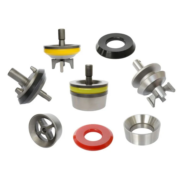
A wide variety of mud pump valve rubber options are available to you, such as 1 year, not available and 3 years.You can also choose from new, used mud pump valve rubber,As well as from energy & mining, construction works , and machinery repair shops. and whether mud pump valve rubber is 1.5 years, 6 months, or unavailable.

My invention relates to valves of the character employed in mud pumps or other pumps adapted to pump fluid mixtures containing abrasive materials, and relates particularly to an improved form of such valve capable of longer periods of uninterrupted use than valves which are at present employed in pumps of this character.
Mud pump valves of the character to which my invention relates are subject to very rapid wear owing to the presence of abrasive materials, such -as fine particles of rocks, quartz, or sand contained in the drilling fluid or mud, and therefore must be replaced after comparatively short periods of use. Such valves ordinarily include a seat member consisting of an annular ring with a sealing seat near the upper end thereof and a spider structure across the lower portion thereof, and a valve element including a body of metal adapted to strike against the spider when the valve element is in lowered or relatively closed position and a sealing member on the metal body adapted to engage the sealing face of the seat member and prevent leakage of fluid through the valve when the valve is in its closed position. It is an object of my invention to provide a valve of the above character of simple construction yet being capable of giving a greater period of service than valves of complex structure.
It is an object of the invention to provide a valve having a seat member including an annular sealing face or seat and a valve closure member having a circular or annular sealing member of rubber material adapted to enter the space enclosed by the annular sealing seat or face of the seat member and to be deformed by fluid pressure so as to expand against the sealing face of the seat member.
It is a further object of the invention to provide a valve of the above character in which the cooperative parts are so formed that the sealing member preferably wipes the sealing face clean as it moves into closed position, thereby reducing to a minimum the particles of abrasive material which may rest between the sealing member and the sealing face, the result thereof being that the wear between these parts is minimized and the useful life of the valve materially extended.
It is a further object of the invention to provide a valve which may be used for abrasive subo5 stances and which may be also employed in pumps for circulating other fluids, such as crude oils.
It is a still further object of the invention to seal the valve by a sealing member on the valve body having a peripheral annular engagement surface adapted to be received within an annular inwardly faced sealing wall surface of the valve seat, whereby the engagement surface is adapted to be deformed radially outwardly for sealing engagement with the sealing wall surface, the seating movement of the valve body being limited by its engagement with a supporting surface of the seat member, and said supporting surface being at an angle to the direction of opening and closing movement of the valve appreciably greater than the angle of the sealing surface with relation to the direction of opening and closing movement of the valve. The supporting surface thus takes the blow and relieves the sealing member of excessive wear as the valve closes, and by its appreciable angle to the axis of the valve prevents radial distortion of the seat member or *swedging action such as might deform the seat or the valve body, while the smaller angle of the sealing surface with relation to the axis of the valve, insures a tight sealing engagement by radially deforming and confining the sealing member within the inwardly faced annular sealing wall surfade, rather than by merely pressing the sealing member against a cooperating surface lying at an appreciable angle to the axis of the valve.
Further objects and advantages of the invention will be made evident throughout the following part of the specification. Referring to the drawings, which are for illustrative purposes only, Fig. 1 is a partly sectioned elevational view showing a mud pump equipped with valves embodying my invention. Fig. 2 is an enlarged fragmentary cross section showing one of the valves in closed position.
Fig. 3 is an enlarged fragmentary sectional view similar to Fig. 2 showing the valve in relatively open position. Fig. 4 is a fragmentary sectional view showing an alternative manner in which clearance may be provided within the periphery of the sealing member of the valve.
Fig. 6 is a fragmentary sectional view showing a form of my invention adapted for use in other types of pumps, such as oil pumps. Fig. 7 is a section on a plane represented by the line 7-7 of Fg. 2.
In Fig. 1 I show a reciprocating pump 10 having a pumping cylinder I in which a piston 12 is reciprocated by a steam powered engine 13. The rightward portion of the pump 10 is sectioned so as to show discharge valves 14 which are connected with the opposite ends of the cylinder II so that as the piston 12 is reciprocated, fluid will be forced upwardly from the respective ends of the cylinder into an outlet chamber 15 which in mud pumps is connected through a rotary hose to the rotary drilling string.
As shown in Fig. 2, the preferred embodiment of my improved valve 14 includes a seat member 16 and a valve body or closure member IT which moves relative to the seat member 16. The seat member 16 includes an annular wall 18 and a support or spider 20 which extends across the lower portion of the annular wall 18, this spider 20 comprising a number of radial arms 21 extending inwardly from the annular wall 18 and a central hub 22 having an axial opening 23 therein.
Above the spider 20 the annular wall 18 is formed with an annular sealing surface 24. This sealing surface is shown as preferably flaring outwardly and upwardly at a comparatively steep angle; or the sealing surface may have no taper but be cylindrical as will be later described with reference to Fig. 5, it being the steep angle of the sealing surface that greatly contributes to the improved operation and wear resisting qualities of my new valve. The valve body I1 is in the form of a metal enlargement 25 having a lower abutment area which includes abutment surfaces adjacent both"the axis and the periphery of said enlargement and adapted, when the valve is closed, to engage the upper face of the hub 22 and the radial arms 21 which constitute the spider. The abutment surface of the enlargement 25 which is adjacent the periphery thereof engages the abutment formed by the arms 21 adjacent and extending inwardly from the annular wall 18, and the abutment surface of the enlargement 25 which is adjacent the axis thereof engages the abutment formed by the hub 22 adjacent the axis of the valve. The enlargement is equipped with guide means in the form of upwardly and downwardly projecting axial stems 26 and 27 of Sthe character commonly employed in mud pump valves. On the upper face of the body IT is a sealing member 30 consisting essentially of a flat disc of yieldable material, such as rubber or rubber compound, having an opening 31 therein through which the stem 26 projects, the sealing member 30 being held in place on the body 1I by a flange member 32 which is held down against the upper face of the sealing member 30 by means of a pin 33 extended through the stem 26. The sealing member 30 is of such external diameter that it will enter the space enclosed by the surface 24 as the closure member T1 moves from the open position in which it is shown in Fig. 3 to the closed position in which it is shown in Fig. 2. As the member I7 moves to closed position fluid pressure within the chamber 15 is exerted downwardly against the annular upwardly directed surface 34 of the sealing member 30 exposed around the flange 32, such pressure compressing the rubber or yieldable material of the peripheralportion of the sealing member 30 against the upper face of the body 17 and causing the periphery of the sealing member 30 to be expanded or deformed radially outwardly so as to be confined within and radially contact the surrounding annular wall surface 24. The sealing member 30 is shown with a shallow peripheral groove 35 so as to form the semblance 7 of a lip 36, but for some uses satisfactory results may be obtained where the upper face of the sealing member 30 is left flat.
A feature of the invention is to make the diameter of the sealing member 30 of such measure relative to the diameter of the sealing surface 24 that not later than when the body 17 engages the spider 20 the fluid pressure in the chamber 15 will have caused the peripheral face 37 of the sealing member to engage the sealing surface 24, with the peripheral face 37 sealing against the sealingsurface 24 when the valve is closed.
Another feature of the invention which may be employed, is to make the diameter of the sealing member 30 of such measure relative to the diameter of the sealing surface 24 that the fluid pressure in the chamber 15 will cause the peripheral face 37 of the sealing member to make wiping contact with the -surface 24 as the closure member 17 moves toward closed position. The sealing member 30 may be of such size that when the body IT, during its downward movement, reaches the position indicated by the dotted lines in Fig. 3, the fluid pressure in the chamber 15 will cause the lower edge of the peripheral face 37 of the sealing member 30 to engage the upper edge of the wall surface 24. As the closure member 14 then continues downwardly toward fully closed position, such as shown in Fig. 2, the surfaces 24 and 37 wipe across one another and remove from each other much of the collected material. It may be that fine abrasive materials will remain on the surfaces 24 and 37, but the condition of the valve after it has been in use for a considerable period of time indicates that this wiping action at least removes the larger partides of material which would prevent a sealing action between the periphery of the sealing member 30 and the wall surface 24. For illustration, as the closure member 17 moves to closed position, the lower peripheral corner 37" of the sealing member may wipe materials from the wall surface 24, and the upper annular corer 38 of the wall surface 24 may wipe materials from the face 37 of the sealing member 30, leaving these surfaces in such condition that a practical seal will, result. .For example, the seal formed is of such practical efficiency that I have been able to employ a single valve structure continuously for a period of over ninety days, replacing the sealing member but once during this period. At the time of signing this application this valve is still in use with the second rubber or sealing member 30.
Another feature of the invention is to yieldably urge the sealing member 30 into sealing engagement with wall surface 24, so that the sealing member may accommodate itself to wear of the metal parts of the valve structure without excessive wear of the resilient sealing member.
For this purpose the flange member 32 is of such restricted diameter that the enlargement 25 as well as the sealing member 30 project appreciably radially beyond the flange member. An appreciable area of the upper surface of the sealing member is thus exposed to the fluid pressure in chamber 15 for tightly seating the sealing member against wall surface 24, and in the event of the metal parts of the assembly being excessively worn so that the sealing member 30 is forced further down into the annular seat 24 before tightly closing the valve, the restricted diameter of the flange member 32 permits such flexing of the outer peripheral portion of the sealing member 30 as will readily adapt it to its new seating position, with said flexing of the outer peripheral portion of the sealing member avoiding cutting through and destruction of the sealing member.
A further feature of my new construction is that the parts are so. formed as to provide an annular space 40 within or below the peripheral edge 37" of the sealing member in which material dislodged from the surface 24 as the valve body moves into closed position may collect. As shown in Fig. 2, the space 40 is a continuous annular space formed by reducing the diameter of tAe body 17 immediately below the sealing member 30. In Fig. 4 I show a space 40a having the same purpose which is formed by chamfering the upper peripheral edge of a body 17a which closely fits the lower portion of the wall surface 24.
In Fig. 5 I show a form of my invention which is exactly the same as the valve shown in Figs. 2 and 3 with the exception that the sealing face or inwardly directed wall surface 24a is cylindrical for a greater part of its length and is slightly chamfered at the corner 38a. Corresponding to the surface 24a, the peripheral surface 37a of the sealing member 30a is cylindrical and may be of such diameter that responsive to fluid pressure, wiping engagement between the surfaces 24a and 37a will be accomplished as the closure member 17a moves into the closed position shown in Fig. 5, it being understood that upon reaching such closed position, fluid pressure against the sealing member causes radial expansion of its annular face 34a into tight sealing engagement with the surface 24a.
In Fig. 5 the wall surface 24a is shown cylindrical for a portion of its length and slightly flared at its upper end. In Figs. 2, 3, and 4, the wall surface 24 is shown comparatively steeply upwardly flared for the purpose of self-adjustment of the parts as the upper face of the support or spider wears down due to the repeated hammering of the body 17 thereagainst during the operation of the pump. Accordingly, in the preferred practice of my invention the wall surface 24 may have such a comparatively steep angle that the annular peripheral engagement surface of the sealing member is adapted to be radially expanded and confined within the annular wall surface 24, and moves relative to surface 24 in the direction of closing movement of the valve so as to permit ready dislodgement of abrasives rather than trapping the same between the surfaces 24-37; and the wall 24 may be flared at such a steep angle as to compensate for the wear between the surfaces 24 and 37 and between the bottom of the body 17 and the upper face of the support 20. As the stopping position of the body 17 moves downwardly as the result of the last named wear, the sealing member, which has worn slightly, assumes a stopping position relative to a lower portion of the wall surface 24 of slightly reduced diameter.
In Fig. 6 I show an alternative form of my valve having a seat member 16 of a form identical with the illustration thereof in Figs. 2, 3, and 4. In this form of the invention, however, the sealing member 30 is replaced by a dished or cupshaped sealing member 50 having a circular wall 51 and an upturned, slightly upwardly flared lip or wall 52 which provides an outer surface 53 adapted to enter the annular wall surface 24 and to be forced outwardly by fluid pressure against the upper and inner faces of the lip 52. The sealing member 50 may be made of leather and may be held in place on the body 17 by use of a flat metal disc 54 of a size to fit under the holddown flange 32. This alternative form of my invention isespecially designed for use in high pressure oil pumps or high pressure pumps for transferring other liquids. The same wiping action between the surfaces 24 and 53 of the members 16 and 50 may be accomplished, and the pounding effect due to the high pressure on the upper face of the movable valve part is received by the spider or support 20.
Another feature of the invention is that the supporting of the seat member which takes the blow when the valve closes, is at an appreciable angle to the direction of opening and closing movement of the valve, while the sealing engagement between surfaces 24-37 is at a slight angle to the direction of opening and closing movement. For example, as shown at Fig. 2, the surface 24 flares upwardly and radially outwardly at a steep angle, and the engagement surface 37 of the sealing member flares upwardly and radially outwardly at substantially the same steep angle; while the upper surface of- pider 20 which provides the abutment surface which takes the blow when the valve closes, is at an angle which is not nearly as steep.
Consequently the hammering blow of the closing valve is directed against the cooperating support of the seat member, at an angle which is at least a near approach to a right angle, so as to avoid swedging action or radial distortion of the seat member; and the sealing engagement at surfaces 24-37 is in a plane which is either parallel or close to parallel to the direction of movement of the valve, whereby material will readily dislodge from between the surfaces 24-37, and the sealing engagement is made by radially outwardly deforming and confirming the sealing member within the annular wall 24. The arresting abutment and the sealing engagement at different angles to the axis of the valve, with the arresting abutment at the greater angle, thus cooperate to define a construction wherein the valve is seated without undue wear of the sealing member and without distortion of either the valve seat or the valve body, and with foreign material dislodged from between the body and seat, and the sealing engagement resulting from radial expansion and confinement of the sealing member within an annular sealing wall of the valve seat.
I claim as my invention: 1. A valve of the character described, including: a seat member comprising an annular wall of short tubular form and a support consisting of an open-work structure extending across one end of said annular wall, the other end of said annular wall providing an outwardly flared, inwardly faced sealing wall surface; a valve body adapted to move to and from said support, said valve body comprising a guide means and an enlargement adapted to engage said support; and an annular sealing member on the upper face of said enlargement having an outwardly flared resilient peripheral portion providing an annular engagement surface adapted to engage said wall surface as said valve body moves into engagement with said support and being of such diameter relative to said wall surface as to engage said wall surface at a point b3fore said enlargement engages said support and to have a wiping movement relative to said wall surface as said enlargement moves from said point into engagement with said support, there being a space below said annular engagement surface to receive the wipings removed from said wall surface by said annular engagement surface, and the peripheral portion of the upper face of said sealing member being exposed to fluid pressure whereby such fluid pressure may deform the periphery of said sealing member outwardly to increase the pressure of the sealing engagement of said sealing member with said wall surface.
2. A valve of the character described, including: a seat member comprising an annular wall of short tubular form and a support consisting of an open-work structure extending across one end of said annular wall, the other end of said annular wall providing an outwardly flared, inwardly faced sealing wall surface; a valve body adapted to move to and from said support, said valve body comprising a guide means and an enlargement adapted to engage said support; and an annular sealing member on the upper face of said enlargement having an outwardly flared resilient peripheral portion providing an annular engagement surface adapted to engage said wall surface as said valve body moves into engagement with said support and being of such diameter relative to said wall surface as to engage said wall surface at a point before said enlargement engages said support and to have a wiping movement relative to said wall surface as said enlargement moves from said point into engagement with said support.
3. A valve of the character described including: a seat member comprising an annular wall and a support below the upper end of the annular wall, the upper end of the annular wall providing an outwardly flaring annular sealing surface; a valve body adapted to move to and from the support, said valve body comprising a guide means and an enlargement adapted to engage the support; and an annular sealing member on the upper face of said enlargement having a resilient peripheral portion providing an annular engagement surface adapted to engage 5o said annular sealing surface as the valve body moves into engagement with the support and being of such diameter relative to the annular sealing surface as to engage said annular sealing surface at a point before said enlargement en5. gages the support and to have wiping movement relative to the annular sealing surface as said enlargement"moves from said point into engagement with the support, there being a space below the annular engagement surface of suffi(; cient size to receive materials wiped from the annular sealing surface by the sealing member as said sealing member moves into closed position relative to the seat member.
4. A valve of the character described includ5, ing: a seat member comprising an annular wall and a support below the upper end of the annular wall, the upper end of the annular wall providing an outwardly flaring annular sealing surface; a valve body adapted to move to and fronh 7o the support; and an annular sealing member on the upper face of the body having an outwardly flared resilient peripheral portion providing an annular engagement surface adapted to engage said annular sealing surface as the valve body moves into engagement with the support and being of such diameter relative to the annular sealing surface as to engage said annular sealing surface at a point before the body engages the support and to have wiping movement relative to the annular sealing surface as the body moves from said point into" engagement with the support, the peripheral portion of the upper face of the sealing member being exposed to fluid pressure whereby such fluid pressure may deform the periphery of the sealing member to increase the pressure of the sealing engagement of the sealing member with the annular sealing surface.
5. A valve of the character described, including: a seat member comprising an annular wall and a support below the upper end of the annular wall, the upper end of the annular wall providing an outwardly flaring annular sealing surface; a valve body adapted to move to and from the support; an annular sealing member on the upper face of the body having a resilient peripheral portion providing an annular engagement surface adapted to engage said annular sealing surface as the valve body moves into engagement with the support and being of such diameter relative to the annular sealing surface as to engage said annular sealing surface at a point before the body engages the support and to have wiping movement relative to the annular sealing surface as the body moves from said point into engagement with the support; and a retaining member overlying the sealing member and of a diameter whereby the sealing member and the valve body project radially beyond the retaining member, so that the peripheral" portion of the sealing member may be flexed to accommodate it to the annular sealing surface and the upper face of said peripheral portion of the sealing member is exposed to fluid pressure whereby such fluid pressure may deform the periphery of the sealing member to increase the pressure of the sealing engagement of the sealing member with the annular sealing surface.
6. In a valve; a seat member comprising an annular wall and an abutment surface below the upper end of and in the bore defined by the annular wall, the abutment surface being adjacent the axis of the annular wall, the upper end of the annular wall providing an outwardly flaring annular sealing surface; a valve body adapted to move to and from the abutment surface parallel to the axis of the annular wall, the abutment surface being adapted for engagement by the valve body at an angle to the axis of the annular wall appreciably greater than the angle of the annular sealing surface to said axis; and an annular sealing member on the valve body having a resilient peripheral portion providing a peripheral engagement surface normally, flaring at substantially the same angle as that of the an- go nular sealing surface and of such diameter as to engage said annular sealing surface before the valve body engages the abutment surface, the peripheral portion of the sealing"member being exposed to fluid pressure for deforming its flar- g6 ing peripheral engagement surface for sealing contact with the annular sealing surface.
7. In a valve; a seat member comprising an annular wall and an abutment surface below the upper end of and in the bore defined by the annular wall, the upper end of the annular wall providing an outwardly flaring annular sealing surface; a valve body adapted to move to and from the abutment surface parallel to the axis of the annular wall, the abutment surface being adapted for engagement by the valve body at an angle to the axis of the annular wall appreciably greater than the angle of the annular sealing surface to said axis; and an annular sealing member on the valve body having a resilient peripheral portion providing a peripheral engagement surface normally flaring at substantially the same angle as that of the annular sealing surface, said peripheral portion of.the sealing member being of such diameter and exposed to fluid pressure so that its flaring peripheral engagement surface engages the annular sealing surface before the valve body engages the abutment surface, and seals against the annular sealing surface when the valve is closed.
8. In a valve; a seat member comprising an annular wall and an abutment surface below the upper end of and in the bore defined by the annular wall, the upper end of the annular wall providing an outwardly flaring annular sealing surface; a valve body adapted to move to and from the abutment surface parallel to the axis of the annular wall, the abutment surface being adapted for engagement by the valve body at an angle to the axis of the annular wall appreciably greater than the angle of the annular sealing surface to said axis; and an annular sealing member on the valve body having a resilient peripheral portion providing a peripheral engagement surface normally flaring at substantially the same angle as that of the annular sealing surface, said peripheral portion of the sealing member being of such diameter and exposed to fluid pressure so that its flaring peripheral engagement surface engages the annular sealing surface before the valve body engages the abutment surface, and seals against the annular sealing surface when the valve is closed; and there being space below said flaring peripheral engagement surface when the valve is closed, adapted to receive material dislodged from the annular sealing surface.
9. In combination; a valve body adapted to move to and from a cooperating annular valve seat parallel to the axis of the valve body; and an annular sealing member on the valve body having, a resilient peripheral portion providing a peripheral engagement surface normally flaring upwardly and outwardly, the valve body having an abutment surface adapted to engage the valve seat, said abutment surface being at an angle to the axis of the valve body appreciably greater than the angle of said flaring peripheral engagement surface to said axis, the flaring peripheral engagement, surface being of such diameter as to engage the valve seat before the abutment surface of the valve body engages the valve seat, and the peripheral portion of the sealing member being exposed to fluid pressure for deforming its flaring peripheral engagement surface for sealing contact with the valve seat.
10. In combination; a valve body adapted to move to and from a cooperating annular valve seat parallel to the axis of the valve body; and an annular sealing member on the upper face of the valve body having a resilient peripheral portion including an upstanding lip providing a peripheral engagement surface normally flaring upwardly and outwardly, the valve body having abutment surfaces adjacent both the periphery and the axis thereof adapted to engage the valve seat, said abutment surface being at angles to the axis of the valve body appreciably greater than the angle of said flaring peripheral engagement surface to said axis, the flaring peripheral engagement surface being of such diameter as to engage the valve seat by the time the abutment surfaces of the valve body engage the valve seat, and the lip of the sealing member being exposed to fluid pressure for deforming the flaring peripheral engagement surface of the sealing member for sealing contact with the Valve seat.
11. In combination; a valve body adapted to move to and from a cooperating annular valve seat parallel to the axis of the valve body; and an annular sealing member on the valve body having a resilient peripheral portion providing a peripheral engagement surface normally flaring upwardly and outwardly, the valve body having an abutment surface adjacent the periphery thereof adapted to engage the valve seat,"said abutment surface being at an angle to the axis of the valve body appreciably greater than the angle of said flaring peripheral engagement surface to said axis, the flaring peripheral engagement surface being of such diameter as to engage the valve seat by the time the abutment surface of the valve body engages the valve seat, and the peripheral portion of the sealing member being exposed to fluid pressure for deforming its flaring peripheral engagement surface for sealing contact with the valve seat.
12. In combination; a valve body adapted to move to and from a cooperating annular valve seat parallel to the axis of the valve body; and an annular sealing member on the valve body having a resilient peripheral portion providing a peripheral engagement surface normally flaring upwardly and outwardly, the valve body having an abutment surface adjacent the axis thereof adapted to engage the valve seat, said abutment surface being at an angle to the axis of the valve body appreciably greater than the angle of said flaring peripheral engagement surface to said axis, the abutment surface being rigid throughout its area, the flaring peripheral engagement surface being of such diameter as to engage the valve seat by the time the abutment surface of the valve body engages the valve seat, and the peripheral portion of the sealing member being exposed to fluid pressure for deforming its flaring peripheral engagement surface for sealing contact with the valve seat.
13. In combination; a valve body adapted to move to and from a cooperating annular valve seat parallel to the axis of the valve body; and an annular sealing member on the valve body having a resilient peripheral portion providing a peripheral engagement surface normally flaring upwardly and outwardly, the valve body having an abutment surface adapted to engage the valve seat, said abutment surface being at an angle to the axis of the valve body appreciably greater than the angle of said flaring peripheral engagement surface to said axis, the abutment surface being rigid throughout its area, the flaring peripheral engagement surface being of such diameter as to engage the valve seat by the time the abutment surface of the valve body engages the valve seat, and the peripheral portion of the sealing member being exposed to fluid pressure for deforming its flaring peripheral engagement surface for sealing contact with the valve seat.
14. In a valve; a seat member comprising an annular wall and an abutment surface below the upper end of and in the bore defined by the annular wall, the abutment surface being adjacent the axis of the annular wall, the upper end of the annular wall providing an outwardly flaring annular sealing surface; a valve body adapted to move to and from the abutment surface parallel to the axis of the annular wall, the abutment surface being" adapted for engagement by the valve body at an angle to the axis of the annular wall appreciably greater than the angle of the annular sealing surface to said axis; an annular sealing member on the upper face of the valve body having a resilient peripheral portion including an upstanding lip providing a peripheral engagement surface normally flaring at substantially the same angle as that of the annular sealing surface and of such diameter as to engage the annular sealing surface by the time the valve body engages the abutment surface; and a retaining member overlying the sealing member and of a diameter less than that of the upstanding lip whereby said lip is exposed to fluid pressure for deforming its flaring peripheral engagement surface for sealing contact with the annular sealing surface; there being space below said flaring peripheral engagement surface when the valve is closed, for reception of material dislodged from the annular sealing surface. 15. In a valve; a seat member comprising an annular wall and an abutment surface below the upper end of and in the bore defined by the annular wall, the upper end of the annular wall providing an outwardly flaring annular sealing surface; a valve body adapted to move to and from the abutment surface parallel to the axis of the annular wall, the abutment surface being adapted for engagement by the valve body at an angle to the axis of the annular wall appreciably 85 greater than the angle of the annular sealing surface to said axis; an annular sealing member on the upper face of the valve body having a resilient peripheral portion providing a peripheral engagement surface normally flaring at substantially the same angle as that.of the annular sealing surface; and a retaining member overlying the sealing member and of a diameter less than that of said peripheral portion of the sealing member, said"peripheral portion of the sealing member being of such diameter and exposed to fluid pressure so that its flaring peripheral engagement surface engages the annular sealing surface by the time the valve body engages the abutment surface, and seals against the annular sealing surface when the valve is closed; the valve body and the sealing member when moved to closed position cooperating with the seat member to define a space for reception of material dislodged from the annular sealing surface.
16. In a valve; a seat member comprising an annular wall and an abutment surface below the upper end of and in the bore defined by the annular wall, the upper end of the annular wall providing an outwardly flaring annular sealing surface; a valve body adapted to move to and from the abutment surface parallel to the axis of the annular wall, the abutment surface being adapted for engagement by the valve body at an angle to the axis of the annular wall appreciably greater than the angle of the annular sealing surface to said axis; an annular sealing member on the upper face of the valve body having a resilient peripheral portion providing a peripheral engagement surface normally flaring at substantially the same angle as that of the annular sealing surface; and a retaining member overlying the sealing member and of a diameter less than that of said peripheral portion of the sealing member, said peripheral portion of the sealing member being of such diameter and exposed to fluid pressure so that its flaring peripheral engagement surface engages the annular sealing surface by the time the valve body engages the abutment surface, and seals against the annular sealing surface when the valve is closed. 17. In combination; a valve body adapted to move to and from a cooperating annular valve seat parallel to the axis of the valve body; and an annular sealing member on the valve body having a resilient peripheral portion providing a peripheral engagement surface normally flaring upwardly and outwardly, the valve body having an abutment surface adjacent the axis thereof adapted to engage the valve seat, said abutment surface being at an angle to the axis of the valve body appreciably greater than the angle of said flaring peripheral engagement surface to said axis, the flaring peripheral engagement surface being of such diameter as to engage the valve seat before the abutment surface of the valve body engages the valve seat; and there being space below said flaring peripheral engagement surface when the valve is closed, adapted to receive material dislodged from the valve seat.

This invention relates to valve assemblies, and more particularly to a valve assembly suited for use, for example, as part of a mud pump used in well drilling operations.
In a typical oil well drilling or well service operation, a positive displacement, reciprocating piston pump is employed to move the drilling mud. Check valve assemblies are connected both to the pump intake and to the pump outlet to ensure that the mud flow is in one direction only as the piston reciprocates.
Valve assemblies for this purpose must function under harsh conditions because the mud contains abrasive particles which wear the valve parts and larger pieces which make a good seal (when the valve assembly is closed) difficult to attain. The valve assembly must function while fluids containing solids and compounds such as acids, pea gravel, sand, liquid carbon dioxide, glass beads, aluminum pellets, mothballs, rock and granulated salt, walnut hulls and cement are flowing through it. The valve assembly must open and close on each reciprocation of the pump piston (up to 1,000 strokes per minute) and therefore it is subjected to constant jarring shocks. Further, it must operate under relatively high pressure conditions, such as up to 20,000 psi.
A typical prior art valve assembly of this nature includes a metal housing, a metal seat formed in the housing, a metal valve which reciprocates to open and close the flow passage, and an elastomeric insert mounted on the valve. The insert, of course, engages the seat to close the passage. The metal parts are accurately machined, and considerable time and expense have been required to manufacture them.
Numerous prior art designs are known. In addition to those shown in FIGS. 1 to 6 herein, John T. Rogers U.S. Pat. No. 4,860,995 shows a design which purports to avoid some of the problems with prior art valves. The Rogers valve includes a metal body part and a plastic insert which forms an upper guide. The plastic insert also includes a flange part which performs the function of the insert of the earlier valves. The metal body part forms a lower guide and supports the plastic insert when the valve is closed.
A valve in accordance with this invention is for use in a valve housing which forms a flow passage, an annular valve seat being provided in the passage and the seat forming an annular seal surface, the housing, the seat and the passage being concentric on a valve axis, the valve including a valve body which reciprocates on said axis in the housing toward and away from the seat, guide means on said valve body for slidingly engaging said seat and guiding the reciprocation of the valve body on said axis, and an annular insert mounted on said valve body adjacent said seal surface and concentric with said axis, said insert comprising a rigid part and a resilient elastomeric seal part, said rigid and seal parts being bonded together, said valve body including a radially extending portion having an outer periphery and a groove formed in said outer periphery, said insert being mounted in said groove with said seal part facing said seal surface, and said outer periphery of said radially extending portion including a flange which overlies said groove and said insert, said flange engaging and supporting said rigid part. Interlock means is also provided between said insert and said radially extending portion.
With reference first to FIG. 1, the prior art valve assembly comprises a valve housing formed by a main housing part 10 and a removable cap 11. A cylindrical cavity 12 is formed within the housing, and the cap 11 closes the upper side of the cavity 12. The cap 11 is removable so that the valve may be repaired. Extending downwardly from the cavity 12 is a circular fluid intake opening formed by a tapered side wall 14. A metal valve seat 16 (also shown in FIG. 3) having a tapered outer surface 17 is tightly mounted within the side wall 14. The valve seat includes a generally cylindrical outer part 18 and a centrally located guide receiver portion 19, the two parts 18 and 19 being connected together by a plurality (in the present instance four) webs 21. During functioning of the valve, fluid flows upwardly (as seen in FIG. 1) through the passages 22 formed between the webs 21 and into the cylindrical cavity 12, and laterally out of the cavity 12 through a radially extending exit flow passage (not illustrated).
Mounted within the valve housing and controlling the flow of the liquid through the passages 22 and into the cavity 12 is a valve 26 formed by a metal main valve body 27, a metal top plate 28 and an insert or elastomeric seal 29. Extending upwardly and downwardly from the main valve body 27 are an upper guide portion 31 and a lower guide portion 32, respectively. The lower guide portion 32 slides within a circular hole 33 formed within the central portion 19 of the valve seat, whereas the upper guide portion 31 slides within a circular hole 34 formed within the cap 11. Threads 36 connect the top plate 28 with the main valve body 27, and the two parts 27 and 28 form a recess 37 between them which receives the elastomeric seal 29. The seal 29 is sized and shaped so that it tightly engages a tapered valve seat surface 38 formed on the valve seat 16. A compression spring 39 extends between the underside of the cap 11 and the top plate 28 and urges the valve to the closed position shown in FIG. 1. The lower end of the compression spring 39 is retained in place by a plurality of posts 41 formed on the upper side of the top plate 28.
During the functioning of the valve shown in FIGS. 1 to 3, pressure of the fluid in the passage 22 on the underside of the valve 26, when it is sufficiently high to overcome the force of the compression spring 39 and the force of the liquid in the cavity 12 acting on the upper side of the valve, will move the valve upwardly such that the seal 29 lifts off of the valve seat surface 38. The liquid then flows upwardly through the passages 22 between the webs 21, through the cavity 12 and out of the outlet. When the differential pressure acting on the valve 26 is such that it is greater on the upper side, the valve moves downwardly to the closed position shown in FIG. 1 and prevents the reverse flow of the liquid from the cavity 12 to the passages 22. The valve guides 31 and 32 slide in the holes 33 and 34 and keep the valve 26 properly centered relative to the valve seat surface.
A problem with the valve shown in FIGS. 1 to 3 is that, during operation, large particles may become lodged between the elastomeric insert 29 and the seat 18. The upper side of the insert 29 is unsupported and may be pushed upwardly by a particle, thereby permitting fluid flow even though the valve is supposed to be closed.
FIGS. 4 and 5 show a prior art valve 46 mounted in a housing 47, an annular seat 48 being mounted in a flow passage 49 of the housing. The valve 46 includes a body 51 and an insert 52, the body 51 having downwardly extending legs 53 which engage the interior of the seat 48 and guide the movement of the valve 46. A compression spring 54 between the cap 56 and the valve 46 urges the valve 46 toward the seat 48.
While the valve shown in FIGS. 4 and 5 has the advantage that the elastomeric seal 62 can be mounted on the body 51 without stretching it and the seal 62 position is held against movement, this valve has the same disadvantage as the FIG. 1 valve in that the seal 62 is not adequately supported. The seal 62 is bonded to the plate 61 and the plate 61 supports the seal 62, but under harsh conditions, as when pumping large solids, a solid may lodge between the insert and the valve seat. The pressure on the valve may be sufficient to bend the plate 61, thereby causing the valve to fail.
The valve shown in FIG. 6 purports to overcome the foregoing disadvantages but introduces a different problem. This valve includes a metal valve body 71 having an elastomeric seal 72 attached to it. A seat 73 is mounted on a valve housing (not illustrated) as previously described, and the underside of the seal 72 is engageable with the seat. Legs 74 are formed on the body 71 and slide on the seat 73. In this instance the legs 74 radiate outwardly from the center of the body 71, and therefore they are spaced farther from the flow past the seal 72.
The annular elastomeric seal 72 is mounted in an annular groove 76 formed in the outer periphery of the valve body 71, and a relatively thick flange 77 of the body 71 overlies the seal 72. An annular counter groove or recess 78 is formed on the radially inner side of the groove 76 and the seal 72 includes a bulge 79 molded thereon which extends into the recess 78. This bulge-recess interconnection prevents the seal 72 from moving downwardly and retains the seal in the groove 76 during operation.
The thick flange 77 is sturdy enough that it will not deform, as will the plate 61, when the valve closes on a large solid, and therefore the upper side of the seal 72 is adequately supported. However, to assemble the seal 72 on the body 71, the seal must be stretched and moved over the legs and the lower part of the valve body, and it is snapped into the groove 76 like a rubber band. The seal continues to be stretched after assembly. This stretching of the seal sometimes causes small tears in the elastomeric seal, and these tears can spread or propagate due to the forces encountered during operation and result in failure. Further, since the seal is not rigidly supported and held in place, large solids can deform the seal and produce a gap between the body and the seal. Smaller particles may become impacted in the gap, causing deformation and failure. Still further, even though the seal 72 has a stretch fit in the groove 76, it may move in the groove. Such movement causes wearing of the adjoining surfaces of the valve body and the seat, leading to a sloppy fit and possible failure.
The valve shown in FIGS. 7 to 9, constructed in accordance with this invention, has the purpose of avoiding the aforementioned disadvantages and problems of the prior art valves. The valve is mounted in a valve housing (not shown) similar to the housing 47 shown in FIG. 4. The valve includes a metal valve body 86 formed by a central stem 87, four legs 88 (FIGS. 7 and 9) which extend radially outwardly and downwardly from the lower end of the stem 87, and a radially extending part 89. The outer edges of the legs 88 slidingly engage the inner surface 91 of an annular seat 92 which is similar to the prior art seats shown in FIGS. 4 and 6. A compression spring 93 (similar to the spring 54) extends around the upper end of the stem 87 and urges the valve toward the seat 92. The lower end of the spring 93 fits in an annular groove 94 formed in the upper surface of the radial part 89.
The valve body 87 has a center line or axis 95, which in operation may be vertical or horizontal, and the valve housing and the seat 92 are concentric with the axis. A flow passage through the housing and the seat is provided when the valve is lifted upwardly off the seat 92.
The insert 96 comprises an annular stiff support plate 101 and a seal 102 which is bonded to the plate 101. The seal 102 is made of a tough resilient material such as rubber, polyurethane or other elastomeric material. The plate 101 is made of a rigid material such as metal or a hard plastic, and it is chemically or mechanically bonded to the seal 102. The plate 101 extends across the upper side of the seal 102 and it engages the underside of the flange 99, and a radially inner bulge 103 of the plate extends into the recess 98 in the groove 97. If desired, one or more small teeth or ridges 104 may be provided on the upper side of the plate 101, which extend into shallow indentations formed in the underside of the flange 99.
The positive displacement mud pump is a key component of the drilling process and its lifespan and reliability are critical to a successful operation.
The fluid end is the most easily damaged part of the mud pump. The pumping process occurs within the fluid end with valves, pistons, and liners. Because these components are high-wear items, many pumps are designed to allow quick replacement of these parts.
Due to the nature of its operation, pistons, liners, and valve assemblies will wear and are considered expendable components. There will be some corrosion and metallurgy imperfections, but the majority of pump failures can be traced back to poor maintenance, errors during the repair process, and pumping drilling fluid with excessive solids content.
A few signs include cut piston rubber, discoloration, pistons that are hard to remove, scored liners, valve and seat pitting or cracks, valve inserts severely worn, cracked, or completely missing, and even drilling fluids making their way to the power end of the pump.
The fluid end of a positive displacement triplex pump presents many opportunities for issues. The results of these issues in such a high-pressure system can mean expensive downtime on the pump itself and, possibly, the entire rig — not to mention the costly repair or replacement of the pump. To reduce severe vibration caused by the pumping process, many pumps incorporate both a suction and discharge pulsation dampener; these are connected to the suction and discharge manifolds of the fluid end. These dampeners reduce the cavitation effect on the entire pump which increases the life of everything within the pump.
Poor maintenance — such as improper valve and seat installation — is another factor. Improper cleaning when replacing a valve seat can leave sand or debris in the valve seat area; preventing the new seat from properly forming a seal with the fluid cylinder, causing a pathway for a washout to occur. It is important to pull up on a seat firmly by hand and make sure it doesn’t pop out and is properly seated. The seats must be seated well, before resuming repairs. You should never reuse a valve seat if at all possible.
The fluid end is the most easily damaged part of the mud pump. The pumping process occurs within the fluid end with valves, pistons, and liners. Because these components are high-wear items, many pumps are designed to allow quick replacement of these parts.
A washout occurs when fluid and solids enter the area behind or underneath a valve seat and erode the sealing surface. Washouts are usually caused by one of three issues: a worn or cracked valve seat, improper cleaning of the valve seat and deck which creates a poor seat seal, and excessive sand content in your drilling fluid. Worn or cracked valve seats can allow fluid to enter the area around the valve seat and seat deck, creating a wash point on the valve seat and causing it to cut into the fluid cylinder and seat deck.
Additionally, the throat (inside diameter) can begin to wash out from extended usage hours or rather quickly when the fluid solids content is excessive. When this happens it can cut all the way through the seat and into the fluid end module/seat deck. This causes excessive expense not only from a parts standpoint but also extended downtime for parts delivery and labor hours to remove and replace the fluid module. With that said, a properly operated and maintained mud recycling system is vital to not only the pump but everything the drilling fluid comes in contact with downstream.

My first days as an MWD field tech I heard horror stories surrounding what is commonly referred to as “pump noise”. I quickly identified the importance of learning to properly identify this “noise”. From the way it was explained to me, this skill might prevent the company you work from losing a job with an exploration company, satisfy your supervisor or even allow you to become regarded as hero within your organization if you’ve proven yourself handy at this skill.
“Pump noise” is a reference to an instability in surface pressure created by the mud pumps on a modern drilling rig, often conflated with any pressure fluctuation at a similar frequency to pulses generated by a mud pulser, but caused by a source external to the mud pulser. This change in pressure is what stands in the way of the decoder properly understanding what the MWD tool is trying to communicate. For the better part of the first year of learning my role I wrongly assumed that all “noise” would be something audible to the human ear, but this is rarely the case.
In an ideal drilling environment surface pressure will remain steady and all pressure increases, and decreases will be gradual. This way, when the pulser valve closes(pulses), it’s easily detectable on surface by computers. Unfortunately drilling environments are rarely perfect and there are many things that can emulate a pulse thus causing poor or inaccurate data delivery to surface. The unfortunate circumstance of this means drilling operations must come to halt until data can once again be decoded on surface. This pause in the drilling process is commonly referred to at NPT or non-productive time. For those of you unfamiliar these concepts, I’ll explain some of the basics.
A mud pulser is a valve that briefly inhibits flow of drilling fluid traveling through the drill string, creating a sharp rise and fall of pressure seen on surface, also known as a “pulse”.
Depending on if the drilling fluid is being circulated in closed or open loop, it will be drawn from a tank or a plastic lined reservoir by a series(or one) mud pumps and channeled into the stand pipe, which runs up the derrick to the Kelly-hose, through the saver sub and down the drill-pipe(drill-string). Through the filter screen past an agitator or exciter, around the MWD tool, through a mud motor and out of the nozzles in the bit. At this point the fluid begins it’s journey back to the drilling rig through the annulus, past the BOP then out of the flow line and either over the shale shakers and/or back in the fluid reservoir.
Developing a firm grasp on these fundamentals were instrumental in my success as a field technician and an effective troubleshooter. As you can tell, there are a lot of components involved in this conduit which a mud pulser telemeters through. The way in which many of these components interact with the drilling fluid can suddenly change in ways that slightly create sharp changes in pressure, often referred to as “noise”. This “noise” creates difficulty for the decoder by suddenly reducing or increasing pressure in a manner that the decoder interprets a pulse. To isolate these issues, you must first acknowledge potential of their existence. I will give few examples of some of these instances below:
Suction screens on intake hoses will occasionally be too large, fail or become unfastened thus allowing large debris in the mud system. Depending on the size of debris and a little bit of luck it can end up in an area that will inhibit flow, circumstantially resulting in a sudden fluctuation of pressure.
Any solid form of drilling fluid additive, if improperly or inconsistently mixed, can restrict the flow path of the fluid resulting in pressure increase. Most notably this can happen at the pulser valve itself, but it is not the only possible outcome. Several other parts of this system can be affected as well. LCM or loss of circulation material is by far the most common additive, but the least overlooked. It’s important for an MWD technician to be aware of what’s being added into the drilling fluid regardless if LCM isn’t present. Through the years I have seen serval other improperly mixed additives cause a litany of pressure related issues.
This specifically is a term used to refer to the mud motor stator rubber deterioration, tearing into small pieces and passing through the nozzles of the bit. Brief spikes in pressure as chunks of rubber pass through one or more nozzles of the bit can often be wrongly interpreted as pulses.
Sometimes when mud is displaced or a pump suction isn’t completely submerged, tiny air bubbles are introduced into the drilling fluid. Being that air compresses and fluid does not, pulses can be significantly diminished and sometimes non-existent.
As many of you know the downhole mud motor is what enables most drilling rigs to steer a well to a targeted location. The motor generates bit RPM by converting fluid velocity to rotor/bit RPM, otherwise known as hydraulic horsepower. Anything downhole that interacts with the bit will inevitably affect surface pressure. One of the most common is bit weight. As bit weight is increased, so does surface pressure. It’s important to note that consistent weight tends to be helpful to the decoder by increasing the amplitude of pulses, but inconsistent bit weight, depending on frequency of change, can negatively affect decoding. Bit bounce, bit bite and inconsistent weight transfer can all cause pressure oscillation resulting in poor decoding. Improper bit speed or bit type relative to a given formation are other examples of possible culprits as well.
Over time mud pump components wear to the point failure. Pump pistons(swabs), liners, valves and valve seats are all necessary components for generating stable pressure. These are the moving parts on the fluid side of the pump and the most frequent point of failure. Another possible culprit but less common is an inadequately charged pulsation dampener. Deteriorating rubber hoses anywhere in the fluid path, from the mud pump to the saver sub, such as a kelly-hose, can cause an occasional pressure oscillation.
If I could change one thing about today’s directional drilling industry, it would be eliminating the term “pump noise”. The misleading term alone has caused confusion for countless people working on a drilling rig. On the other hand, I’m happy to have learned these lessons the hard way because they seem engrained into my memory. As technology improves, so does the opportunities for MWD technology companies to provide useful solutions. Solutions to aid MWD service providers to properly isolate or overcome the challenges that lead to decoding issues. As an industry we have come a lot further from when I had started, but there is much left to be desired. I’m happy I can use my experiences by contributing to an organization capable of acknowledging and overcoming these obstacles through the development of new technology.

Mechanical pumps serve in a wide range of applications such as pumping water from wells, aquarium filtering, pond filtering and aeration, in the car industry for water-cooling and fuel injection, in the energy industry for pumping oil and natural gas or for operating cooling towers and other components of heating, ventilation and air conditioning systems. In the medical industry, pumps are used for biochemical processes in developing and manufacturing medicine, and as artificial replacements for body parts, in particular the artificial heart and penile prosthesis.
When a pump contains two or more pump mechanisms with fluid being directed to flow through them in series, it is called a multi-stage pump. Terms such as two-stage or double-stage may be used to specifically describe the number of stages. A pump that does not fit this description is simply a single-stage pump in contrast.
In biology, many different types of chemical and biomechanical pumps have evolved; biomimicry is sometimes used in developing new types of mechanical pumps.
Pumps can be classified by their method of displacement into positive-displacement pumps, impulse pumps, velocity pumps, gravity pumps, steam pumps and valveless pumps. There are three basic types of pumps: positive-displacement, centrifugal and axial-flow pumps. In centrifugal pumps the direction of flow of the fluid changes by ninety degrees as it flows over an impeller, while in axial flow pumps the direction of flow is unchanged.
Some positive-displacement pumps use an expanding cavity on the suction side and a decreasing cavity on the discharge side. Liquid flows into the pump as the cavity on the suction side expands and the liquid flows out of the discharge as the cavity collapses. The volume is constant through each cycle of operation.
Positive-displacement pumps, unlike centrifugal, can theoretically produce the same flow at a given speed (rpm) no matter what the discharge pressure. Thus, positive-displacement pumps are constant flow machines. However, a slight increase in internal leakage as the pressure increases prevents a truly constant flow rate.
A positive-displacement pump must not operate against a closed valve on the discharge side of the pump, because it has no shutoff head like centrifugal pumps. A positive-displacement pump operating against a closed discharge valve continues to produce flow and the pressure in the discharge line increases until the line bursts, the pump is severely damaged, or both.
A relief or safety valve on the discharge side of the positive-displacement pump is therefore necessary. The relief valve can be internal or external. The pump manufacturer normally has the option to supply internal relief or safety valves. The internal valve is usually used only as a safety precaution. An external relief valve in the discharge line, with a return line back to the suction line or supply tank provides increased safety.
Rotary-type positive displacement: internal or external gear pump, screw pump, lobe pump, shuttle block, flexible vane or sliding vane, circumferential piston, flexible impeller, helical twisted roots (e.g. the Wendelkolben pump) or liquid-ring pumps
Drawbacks: The nature of the pump requires very close clearances between the rotating pump and the outer edge, making it rotate at a slow, steady speed. If rotary pumps are operated at high speeds, the fluids cause erosion, which eventually causes enlarged clearances that liquid can pass through, which reduces efficiency.
Hollow disk pumps (also known as eccentric disc pumps or Hollow rotary disc pumps), similar to scroll compressors, these have a cylindrical rotor encased in a circular housing. As the rotor orbits and rotates to some degree, it traps fluid between the rotor and the casing, drawing the fluid through the pump. It is used for highly viscous fluids like petroleum-derived products, and it can also support high pressures of up to 290 psi.
Vibratory pumps or vibration pumps are similar to linear compressors, having the same operating principle. They work by using a spring-loaded piston with an electromagnet connected to AC current through a diode. The spring-loaded piston is the only moving part, and it is placed in the center of the electromagnet. During the positive cycle of the AC current, the diode allows energy to pass through the electromagnet, generating a magnetic field that moves the piston backwar


 8613371530291