
mud pump wikipedia factory

A mud pump (sometimes referred to as a mud drilling pump or drilling mud pump), is a reciprocating piston/plunger pump designed to circulate drilling fluid under high pressure (up to 7,500 psi or 52,000 kPa) down the drill string and back up the annulus. A mud pump is an important part of the equipment used for oil well drilling.
Mud pumps can be divided into single-acting pump and double-acting pump according to the completion times of the suction and drainage acting in one cycle of the piston"s reciprocating motion.
Mud pumps come in a variety of sizes and configurations but for the typical petroleum drilling rig, the triplex (three piston/plunger) mud pump is used. Duplex mud pumps (two piston/plungers) have generally been replaced by the triplex pump, but are still common in developing countries. Two later developments are the hex pump with six vertical pistons/plungers, and various quintuplexes with five horizontal piston/plungers. The advantages that these new pumps have over convention triplex pumps is a lower mud noise which assists with better measurement while drilling (MWD) and logging while drilling (LWD) decoding.
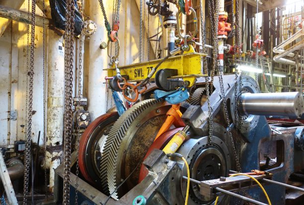
The fluid end produces the pumping process with valves, pistons, and liners. Because these components are high-wear items, modern pumps are designed to allow quick replacement of these parts.
To reduce severe vibration caused by the pumping process, these pumps incorporate both a suction and discharge pulsation dampener. These are connected to the inlet and outlet of the fluid end.
The pressure of the pump depends on the depth of the drilling hole, the resistance of flushing fluid (drilling fluid) through the channel, as well as the nature of the conveying drilling fluid. The deeper the drilling hole and the greater the pipeline resistance, the higher the pressure needed.
With the changes of drilling hole diameter and depth, the displacement of the pump can be adjusted accordingly. In the mud pump mechanism, the gearbox or hydraulic motor is equipped to adjust its speed and displacement. In order to accurately measure the changes in pressure and displacement, a flow meter and pressure gauge are installed in the mud pump.
The construction department should have a special maintenance worker that is responsible for the maintenance and repair of the machine. Mud pumps and other mechanical equipment should be inspected and maintained on a scheduled and timely basis to find and address problems ahead of time, in order to avoid unscheduled shutdown. The worker should attend to the size of the sediment particles; if large particles are found, the mud pump parts should be checked frequently for wear, to see if they need to be repaired or replaced. The wearing parts for mud pumps include pump casing, bearings, impeller, piston, liner, etc. Advanced anti-wear measures should be adopted to increase the service life of the wearing parts, which can reduce the investment cost of the project, and improve production efficiency. At the same time, wearing parts and other mud pump parts should be repaired rather than replaced when possible.

Mechanical pumps serve in a wide range of applications such as pumping water from wells, aquarium filtering, pond filtering and aeration, in the car industry for water-cooling and fuel injection, in the energy industry for pumping oil and natural gas or for operating cooling towers and other components of heating, ventilation and air conditioning systems. In the medical industry, pumps are used for biochemical processes in developing and manufacturing medicine, and as artificial replacements for body parts, in particular the artificial heart and penile prosthesis.
When a pump contains two or more pump mechanisms with fluid being directed to flow through them in series, it is called a multi-stage pump. Terms such as two-stage or double-stage may be used to specifically describe the number of stages. A pump that does not fit this description is simply a single-stage pump in contrast.
In biology, many different types of chemical and biomechanical pumps have evolved; biomimicry is sometimes used in developing new types of mechanical pumps.
Pumps can be classified by their method of displacement into positive-displacement pumps, impulse pumps, velocity pumps, gravity pumps, steam pumps and valveless pumps. There are three basic types of pumps: positive-displacement, centrifugal and axial-flow pumps. In centrifugal pumps the direction of flow of the fluid changes by ninety degrees as it flows over an impeller, while in axial flow pumps the direction of flow is unchanged.
Some positive-displacement pumps use an expanding cavity on the suction side and a decreasing cavity on the discharge side. Liquid flows into the pump as the cavity on the suction side expands and the liquid flows out of the discharge as the cavity collapses. The volume is constant through each cycle of operation.
Positive-displacement pumps, unlike centrifugal, can theoretically produce the same flow at a given speed (rpm) no matter what the discharge pressure. Thus, positive-displacement pumps are constant flow machines. However, a slight increase in internal leakage as the pressure increases prevents a truly constant flow rate.
A positive-displacement pump must not operate against a closed valve on the discharge side of the pump, because it has no shutoff head like centrifugal pumps. A positive-displacement pump operating against a closed discharge valve continues to produce flow and the pressure in the discharge line increases until the line bursts, the pump is severely damaged, or both.
A relief or safety valve on the discharge side of the positive-displacement pump is therefore necessary. The relief valve can be internal or external. The pump manufacturer normally has the option to supply internal relief or safety valves. The internal valve is usually used only as a safety precaution. An external relief valve in the discharge line, with a return line back to the suction line or supply tank provides increased safety.
Rotary-type positive displacement: internal or external gear pump, screw pump, lobe pump, shuttle block, flexible vane or sliding vane, circumferential piston, flexible impeller, helical twisted roots (e.g. the Wendelkolben pump) or liquid-ring pumps
Drawbacks: The nature of the pump requires very close clearances between the rotating pump and the outer edge, making it rotate at a slow, steady speed. If rotary pumps are operated at high speeds, the fluids cause erosion, which eventually causes enlarged clearances that liquid can pass through, which reduces efficiency.
Hollow disk pumps (also known as eccentric disc pumps or Hollow rotary disc pumps), similar to scroll compressors, these have a cylindrical rotor encased in a circular housing. As the rotor orbits and rotates to some degree, it traps fluid between the rotor and the casing, drawing the fluid through the pump. It is used for highly viscous fluids like petroleum-derived products, and it can also support high pressures of up to 290 psi.
Vibratory pumps or vibration pumps are similar to linear compressors, having the same operating principle. They work by using a spring-loaded piston with an electromagnet connected to AC current through a diode. The spring-loaded piston is the only moving part, and it is placed in the center of the electromagnet. During the positive cycle of the AC current, the diode allows energy to pass through the electromagnet, generating a magnetic field that moves the piston backwards, compressing the spring, and generating suction. During the negative cycle of the AC current, the diode blocks current flow to the electromagnet, letting the spring uncompress, moving the piston forward, and pumping the fluid and generating pressure, like a reciprocating pump. Due to its low cost, it is widely used in inexpensive espresso machines. However, vibratory pumps cannot be operated for more than one minute, as they generate large amounts of heat. Linear compressors do not have this problem, as they can be cooled by the working fluid (which is often a refrigerant).
Reciprocating pumps move the fluid using one or more oscillating pistons, plungers, or membranes (diaphragms), while valves restrict fluid motion to the desired direction. In order for suction to take place, the pump must first pull the plunger in an outward motion to decrease pressure in the chamber. Once the plunger pushes back, it will increase the chamber pressure and the inward pressure of the plunger will then open the discharge valve and release the fluid into the delivery pipe at constant flow rate and increased pressure.
Pumps in this category range from simplex, with one cylinder, to in some cases quad (four) cylinders, or more. Many reciprocating-type pumps are duplex (two) or triplex (three) cylinder. They can be either single-acting with suction during one direction of piston motion and discharge on the other, or double-acting with suction and discharge in both directions. The pumps can be powered manually, by air or steam, or by a belt driven by an engine. This type of pump was used extensively in the 19th century—in the early days of steam propulsion—as boiler feed water pumps. Now reciprocating pumps typically pump highly viscous fluids like concrete and heavy oils, and serve in special applications that demand low flow rates against high resistance. Reciprocating hand pumps were widely used to pump water from wells. Common bicycle pumps and foot pumps for inflation use reciprocating action.
These positive-displacement pumps have an expanding cavity on the suction side and a decreasing cavity on the discharge side. Liquid flows into the pumps as the cavity on the suction side expands and the liquid flows out of the discharge as the cavity collapses. The volume is constant given each cycle of operation and the pump"s volumetric efficiency can be achieved through routine maintenance and inspection of its valves.
This is the simplest form of rotary positive-displacement pumps. It consists of two meshed gears that rotate in a closely fitted casing. The tooth spaces trap fluid and force it around the outer periphery. The fluid does not travel back on the meshed part, because the teeth mesh closely in the center. Gear pumps see wide use in car engine oil pumps and in various hydraulic power packs.
A screw pump is a more complicated type of rotary pump that uses two or three screws with opposing thread — e.g., one screw turns clockwise and the other counterclockwise. The screws are mounted on parallel shafts that have gears that mesh so the shafts turn together and everything stays in place. The screws turn on the shafts and drive fluid through the pump. As with other forms of rotary pumps, the clearance between moving parts and the pump"s casing is minimal.
Widely used for pumping difficult materials, such as sewage sludge contaminated with large particles, a progressing cavity pump consists of a helical rotor, about ten times as long as its width. This can be visualized as a central core of diameter x with, typically, a curved spiral wound around of thickness half x, though in reality it is manufactured in a single casting. This shaft fits inside a heavy-duty rubber sleeve, of wall thickness also typically x. As the shaft rotates, the rotor gradually forces fluid up the rubber sleeve. Such pumps can develop very high pressure at low volumes.
Named after the Roots brothers who invented it, this lobe pump displaces the fluid trapped between two long helical rotors, each fitted into the other when perpendicular at 90°, rotating inside a triangular shaped sealing line configuration, both at the point of suction and at the point of discharge. This design produces a continuous flow with equal volume and no vortex. It can work at low pulsation rates, and offers gentle performance that some applications require.
A peristaltic pump is a type of positive-displacement pump. It contains fluid within a flexible tube fitted inside a circular pump casing (though linear peristaltic pumps have been made). A number of rollers, shoes, or wipers attached to a rotor compresses the flexible tube. As the rotor turns, the part of the tube under compression closes (or occludes), forcing the fluid through the tube. Additionally, when the tube opens to its natural state after the passing of the cam it draws (restitution) fluid into the pump. This process is called peristalsis and is used in many biological systems such as the gastrointestinal tract.
Efficiency and common problems: With only one cylinder in plunger pumps, the fluid flow varies between maximum flow when the plunger moves through the middle positions, and zero flow when the plunger is at the end positions. A lot of energy is wasted when the fluid is accelerated in the piping system. Vibration and
Triplex plunger pumps use three plungers, which reduces the pulsation of single reciprocating plunger pumps. Adding a pulsation dampener on the pump outlet can further smooth the pump ripple, or ripple graph of a pump transducer. The dynamic relationship of the high-pressure fluid and plunger generally requires high-quality plunger seals. Plunger pumps with a larger number of plungers have the benefit of increased flow, or smoother flow without a pulsation damper. The increase in moving parts and crankshaft load is one drawback.
Car washes often use these triplex-style plunger pumps (perhaps without pulsation dampers). In 1968, William Bruggeman reduced the size of the triplex pump and increased the lifespan so that car washes could use equipment with smaller footprints. Durable high-pressure seals, low-pressure seals and oil seals, hardened crankshafts, hardened connecting rods, thick ceramic plungers and heavier duty ball and roller bearings improve reliability in triplex pumps. Triplex pumps now are in a myriad of markets across the world.
Triplex pumps with shorter lifetimes are commonplace to the home user. A person who uses a home pressure washer for 10 hours a year may be satisfied with a pump that lasts 100 hours between rebuilds. Industrial-grade or continuous duty triplex pumps on the other end of the quality spectrum may run for as much as 2,080 hours a year.
The oil and gas drilling industry uses massive semi trailer-transported triplex pumps called mud pumps to pump drilling mud, which cools the drill bit and carries the cuttings back to the surface.
One modern application of positive-displacement pumps is compressed-air-powered double-diaphragm pumps. Run on compressed air, these pumps are intrinsically safe by design, although all manufacturers offer ATEX certified models to comply with industry regulation. These pumps are relatively inexpensive and can perform a wide variety of duties, from pumping water out of bunds to pumping hydrochloric acid from secure storage (dependent on how the pump is manufactured – elastomers / body construction). These double-diaphragm pumps can handle viscous fluids and abrasive materials with a gentle pumping process ideal for transporting shear-sensitive media.
Devised in China as chain pumps over 1000 years ago, these pumps can be made from very simple materials: A rope, a wheel and a pipe are sufficient to make a simple rope pump. Rope pump efficiency has been studied by grassroots organizations and the techniques for making and running them have been continuously improved.
Impulse pumps use pressure created by gas (usually air). In some impulse pumps the gas trapped in the liquid (usually water), is released and accumulated somewhere in the pump, creating a pressure that can push part of the liquid upwards.
Instead of a gas accumulation and releasing cycle, the pressure can be created by burning of hydrocarbons. Such combustion driven pumps directly transmit the impulse from a combustion event through the actuation membrane to the pump fluid. In order to allow this direct transmission, the pump needs to be almost entirely made of an elastomer (e.g. silicone rubber). Hence, the combustion causes the membrane to expand and thereby pumps the fluid out of the adjacent pumping chamber. The first combustion-driven soft pump was developed by ETH Zurich.
It takes in water at relatively low pressure and high flow-rate and outputs water at a higher hydraulic-head and lower flow-rate. The device uses the water hammer effect to develop pressure that lifts a portion of the input water that powers the pump to a point higher than where the water started.
The hydraulic ram is sometimes used in remote areas, where there is both a source of low-head hydropower, and a need for pumping water to a destination higher in elevation than the source. In this situation, the ram is often useful, since it requires no outside source of power other than the kinetic energy of flowing water.
Rotodynamic pumps (or dynamic pumps) are a type of velocity pump in which kinetic energy is added to the fluid by increasing the flow velocity. This increase in energy is converted to a gain in potential energy (pressure) when the velocity is reduced prior to or as the flow exits the pump into the discharge pipe. This conversion of kinetic energy to pressure is explained by the
A practical difference between dynamic and positive-displacement pumps is how they operate under closed valve conditions. Positive-displacement pumps physically displace fluid, so closing a valve downstream of a positive-displacement pump produces a continual pressure build up that can cause mechanical failure of pipeline or pump. Dynamic pumps differ in that they can be safely operated under closed valve conditions (for short periods of time).
Such a pump is also referred to as a centrifugal pump. The fluid enters along the axis or center, is accelerated by the impeller and exits at right angles to the shaft (radially); an example is the centrifugal fan, which is commonly used to implement a vacuum cleaner. Another type of radial-flow pump is a vortex pump. The liquid in them moves in tangential direction around the working wheel. The conversion from the mechanical energy of motor into the potential energy of flow comes by means of multiple whirls, which are excited by the impeller in the working channel of the pump. Generally, a radial-flow pump operates at higher pressures and lower flow rates than an axial- or a mixed-flow pump.
These are also referred to as All fluid pumps. The fluid is pushed outward or inward to move fluid axially. They operate at much lower pressures and higher flow rates than radial-flow (centrifugal) pumps. Axial-flow pumps cannot be run up to speed without special precaution. If at a low flow rate, the total head rise and high torque associated with this pipe would mean that the starting torque would have to become a function of acceleration for the whole mass of liquid in the pipe system. If there is a large amount of fluid in the system, accelerate the pump slowly.
Mixed-flow pumps function as a compromise between radial and axial-flow pumps. The fluid experiences both radial acceleration and lift and exits the impeller somewhere between 0 and 90 degrees from the axial direction. As a consequence mixed-flow pumps operate at higher pressures than axial-flow pumps while delivering higher discharges than radial-flow pumps. The exit angle of the flow dictates the pressure head-discharge characteristic in relation to radial and mixed-flow.
Regenerative turbine pump rotor and housing, 1⁄3 horsepower (0.25 kW). 85 millimetres (3.3 in) diameter impeller rotates counter-clockwise. Left: inlet, right: outlet. .4 millimetres (0.016 in) thick vanes on 4 millimetres (0.16 in) centers
Also known as drag, friction, peripheral, traction, turbulence, or vortex pumps, regenerative turbine pumps are class of rotodynamic pump that operates at high head pressures, typically 4–20 bars (4.1–20.4 kgf/cm2; 58–290 psi).
The pump has an impeller with a number of vanes or paddles which spins in a cavity. The suction port and pressure ports are located at the perimeter of the cavity and are isolated by a barrier called a stripper, which allows only the tip channel (fluid between the blades) to recirculate, and forces any fluid in the side channel (fluid in the cavity outside of the blades) through the pressure port. In a regenerative turbine pump, as fluid spirals repeatedly from a vane into the side channel and back to the next vane, kinetic energy is imparted to the periphery,
As regenerative turbine pumps cannot become vapor locked, they are commonly applied to volatile, hot, or cryogenic fluid transport. However, as tolerances are typically tight, they are vulnerable to solids or particles causing jamming or rapid wear. Efficiency is typically low, and pressure and power consumption typically decrease with flow. Additionally, pumping direction can be reversed by reversing direction of spin.
Steam pumps have been for a long time mainly of historical interest. They include any type of pump powered by a steam engine and also pistonless pumps such as Thomas Savery"s or the Pulsometer steam pump.
Recently there has been a resurgence of interest in low power solar steam pumps for use in smallholder irrigation in developing countries. Previously small steam engines have not been viable because of escalating inefficiencies as vapour engines decrease in size. However the use of modern engineering materials coupled with alternative engine configurations has meant that these types of system are now a cost-effective opportunity.
Valveless pumping assists in fluid transport in various biomedical and engineering systems. In a valveless pumping system, no valves (or physical occlusions) are present to regulate the flow direction. The fluid pumping efficiency of a valveless system, however, is not necessarily lower than that having valves. In fact, many fluid-dynamical systems in nature and engineering more or less rely upon valveless pumping to transport the working fluids therein. For instance, blood circulation in the cardiovascular system is maintained to some extent even when the heart"s valves fail. Meanwhile, the embryonic vertebrate heart begins pumping blood long before the development of discernible chambers and valves. Similar to blood circulation in one direction, bird respiratory systems pump air in one direction in rigid lungs, but without any physiological valve. In microfluidics, valveless impedance pumps have been fabricated, and are expected to be particularly suitable for handling sensitive biofluids. Ink jet printers operating on the piezoelectric transducer principle also use valveless pumping. The pump chamber is emptied through the printing jet due to reduced flow impedance in that direction and refilled by capillary action.
Examining pump repair records and mean time between failures (MTBF) is of great importance to responsible and conscientious pump users. In view of that fact, the preface to the 2006 Pump User"s Handbook alludes to "pump failure" statistics. For the sake of convenience, these failure statistics often are translated into MTBF (in this case, installed life before failure).
In early 2005, Gordon Buck, John Crane Inc.’s chief engineer for field operations in Baton Rouge, Louisiana, examined the repair records for a number of refinery and chemical plants to obtain meaningful reliability data for centrifugal pumps. A total of 15 operating plants having nearly 15,000 pumps were included in the survey. The smallest of these plants had about 100 pumps; several plants had over 2000. All facilities were located in the United States. In addition, considered as "new", others as "renewed" and still others as "established". Many of these plants—but not all—had an alliance arrangement with John Crane. In some cases, the alliance contract included having a John Crane Inc. technician or engineer on-site to coordinate various aspects of the program.
Not all plants are refineries, however, and different results occur elsewhere. In chemical plants, pumps have historically been "throw-away" items as chemical attack limits life. Things have improved in recent years, but the somewhat restricted space available in "old" DIN and ASME-standardized stuffing boxes places limits on the type of seal that fits. Unless the pump user upgrades the seal chamber, the pump only accommodates more compact and simple versions. Without this upgrading, lifetimes in chemical installations are generally around 50 to 60 percent of the refinery values.
Unscheduled maintenance is often one of the most significant costs of ownership, and failures of mechanical seals and bearings are among the major causes. Keep in mind the potential value of selecting pumps that cost more initially, but last much longer between repairs. The MTBF of a better pump may be one to four years longer than that of its non-upgraded counterpart. Consider that published average values of avoided pump failures range from US$2600 to US$12,000. This does not include lost opportunity costs. One pump fire occurs per 1000 failures. Having fewer pump failures means having fewer destructive pump fires.
As has been noted, a typical pump failure, based on actual year 2002 reports, costs US$5,000 on average. This includes costs for material, parts, labor and overhead. Extending a pump"s MTBF from 12 to 18 months would save US$1,667 per year — which might be greater than the cost to upgrade the centrifugal pump"s reliability.
Pumps are used throughout society for a variety of purposes. Early applications includes the use of the windmill or watermill to pump water. Today, the pump is used for irrigation, water supply, gasoline supply, air conditioning systems, refrigeration (usually called a compressor), chemical movement, sewage movement, flood control, marine services, etc.
Because of the wide variety of applications, pumps have a plethora of shapes and sizes: from very large to very small, from handling gas to handling liquid, from high pressure to low pressure, and from high volume to low volume.
Typically, a liquid pump can"t simply draw air. The feed line of the pump and the internal body surrounding the pumping mechanism must first be filled with the liquid that requires pumping: An operator must introduce liquid into the system to initiate the pumping. This is called priming the pump. Loss of prime is usually due to ingestion of air into the pump. The clearances and displacement ratios in pumps for liquids, whether thin or more viscous, usually cannot displace air due to its compressibility. This is the case with most velocity (rotodynamic) pumps — for example, centrifugal pumps. For such pumps, the position of the pump should always be lower than the suction point, if not the pump should be manually filled with liquid or a secondary pump should be used until all air is removed from the suction line and the pump casing.
Positive–displacement pumps, however, tend to have sufficiently tight sealing between the moving parts and the casing or housing of the pump that they can be described as self-priming. Such pumps can also serve as priming pumps, so-called when they are used to fulfill that need for other pumps in lieu of action taken by a human operator.
One sort of pump once common worldwide was a hand-powered water pump, or "pitcher pump". It was commonly installed over community water wells in the days before piped water supplies.
In parts of the British Isles, it was often called the parish pump. Though such community pumps are no longer common, people still used the expression parish pump to describe a place or forum where matters of local interest are discussed.
Because water from pitcher pumps is drawn directly from the soil, it is more prone to contamination. If such water is not filtered and purified, consumption of it might lead to gastrointestinal or other water-borne diseases. A notorious case is the 1854 Broad Street cholera outbreak. At the time it was not known how cholera was transmitted, but physician John Snow suspected contaminated water and had the handle of the public pump he suspected removed; the outbreak then subsided.
Modern hand-operated community pumps are considered the most sustainable low-cost option for safe water supply in resource-poor settings, often in rural areas in developing countries. A hand pump opens access to deeper groundwater that is often not polluted and also improves the safety of a well by protecting the water source from contaminated buckets. Pumps such as the Afridev pump are designed to be cheap to build and install, and easy to maintain with simple parts. However, scarcity of spare parts for these type of pumps in some regions of Africa has diminished their utility for these areas.
Multiphase pumping applications, also referred to as tri-phase, have grown due to increased oil drilling activity. In addition, the economics of multiphase production is attractive to upstream operations as it leads to simpler, smaller in-field installations, reduced equipment costs and improved production rates. In essence, the multiphase pump can accommodate all fluid stream properties with one piece of equipment, which has a smaller footprint. Often, two smaller multiphase pumps are installed in series rather than having just one massive pump.
A rotodynamic pump with one single shaft that requires two mechanical seals, this pump uses an open-type axial impeller. It is often called a Poseidon pump, and can be described as a cross between an axial compressor and a centrifugal pump.
The twin-screw pump is constructed of two inter-meshing screws that move the pumped fluid. Twin screw pumps are often used when pumping conditions contain high gas volume fractions and fluctuating inlet conditions. Four mechanical seals are required to seal the two shafts.
These pumps are basically multistage centrifugal pumps and are widely used in oil well applications as a method for artificial lift. These pumps are usually specified when the pumped fluid is mainly liquid.
A buffer tank is often installed upstream of the pump suction nozzle in case of a slug flow. The buffer tank breaks the energy of the liquid slug, smooths any fluctuations in the incoming flow and acts as a sand trap.
As the name indicates, multiphase pumps and their mechanical seals can encounter a large variation in service conditions such as changing process fluid composition, temperature variations, high and low operating pressures and exposure to abrasive/erosive media. The challenge is selecting the appropriate mechanical seal arrangement and support system to ensure maximized seal life and its overall effectiveness.
Pumps are commonly rated by horsepower, volumetric flow rate, outlet pressure in metres (or feet) of head, inlet suction in suction feet (or metres) of head.
From an initial design point of view, engineers often use a quantity termed the specific speed to identify the most suitable pump type for a particular combination of flow rate and head.
The power imparted into a fluid increases the energy of the fluid per unit volume. Thus the power relationship is between the conversion of the mechanical energy of the pump mechanism and the fluid elements within the pump. In general, this is governed by a series of simultaneous differential equations, known as the Navier–Stokes equations. However a more simple equation relating only the different energies in the fluid, known as Bernoulli"s equation can be used. Hence the power, P, required by the pump:
where Δp is the change in total pressure between the inlet and outlet (in Pa), and Q, the volume flow-rate of the fluid is given in m3/s. The total pressure may have gravitational, static pressure and kinetic energy components; i.e. energy is distributed between change in the fluid"s gravitational potential energy (going up or down hill), change in velocity, or change in static pressure. η is the pump efficiency, and may be given by the manufacturer"s information, such as in the form of a pump curve, and is typically derived from either fluid dynamics simulation (i.e. solutions to the Navier–Stokes for the particular pump geometry), or by testing. The efficiency of the pump depends upon the pump"s configuration and operating conditions (such as rotational speed, fluid density and viscosity etc.)
For a typical "pumping" configuration, the work is imparted on the fluid, and is thus positive. For the fluid imparting the work on the pump (i.e. a turbine), the work is negative. Power required to drive the pump is determined by dividing the output power by the pump efficiency. Furthermore, this definition encompasses pumps with no moving parts, such as a siphon.
Pump efficiency is defined as the ratio of the power imparted on the fluid by the pump in relation to the power supplied to drive the pump. Its value is not fixed for a given pump, efficiency is a function of the discharge and therefore also operating head. For centrifugal pumps, the efficiency tends to increase with flow rate up to a point midway through the operating range (peak efficiency or Best Efficiency Point (BEP) ) and then declines as flow rates rise further. Pump performance data such as this is usually supplied by the manufacturer before pump selection. Pump efficiencies tend to decline over time due to wear (e.g. increasing clearances as impellers reduce in size).
When a system includes a centrifugal pump, an important design issue is matching the head loss-flow characteristic with the pump so that it operates at or close to the point of its maximum efficiency.
Most large pumps have a minimum flow requirement below which the pump may be damaged by overheating, impeller wear, vibration, seal failure, drive shaft damage or poor performance.
The simplest minimum flow system is a pipe running from the pump discharge line back to the suction line. This line is fitted with an orifice plate sized to allow the pump minimum flow to pass.
A more sophisticated, but more costly, system (see diagram) comprises a flow measuring device (FE) in the pump discharge which provides a signal into a flow controller (FIC) which actuates a flow control valve (FCV) in the recycle line. If the measured flow exceeds the minimum flow then the FCV is closed. If the measured flow falls below the minimum flow the FCV opens to maintain the minimum flowrate.
As the fluids are recycled the kinetic energy of the pump increases the temperature of the fluid. For many pumps this added heat energy is dissipated through the pipework. However, for large industrial pumps, such as oil pipeline pumps, a recycle cooler is provided in the recycle line to cool the fluids to the normal suction temperature.oil refinery, oil terminal, or offshore installation.
Engineering Sciences Data Unit (2007). "Radial, mixed and axial flow pumps. Introduction" (PDF). Archived from the original (PDF) on 2014-03-08. Retrieved 2017-08-18.
Tanzania water Archived 2012-03-31 at the Wayback Machine blog – example of grassroots researcher telling about his study and work with the rope pump in Africa.
C.M. Schumacher, M. Loepfe, R. Fuhrer, R.N. Grass, and W.J. Stark, "3D printed lost-wax casted soft silicone monoblocks enable heart-inspired pumping by internal combustion," RSC Advances, Vol. 4, pp. 16039–16042, 2014.
"Radial, mixed and axial flow pumps" (PDF). Institution of Diploma Marine Engineers, Bangladesh. June 2003. Archived from the original (PDF) on 2014-03-08. Retrieved 2017-08-18.
Quail F, Scanlon T, Stickland M (2011-01-11). "Design optimisation of a regenerative pump using numerical and experimental techniques" (PDF). International Journal of Numerical Methods for Heat & Fluid Flow. 21: 95–111. doi:10.1108/09615531111095094. Retrieved 2021-07-21.
Rajmane, M. Satish; Kallurkar, S.P. (May 2015). "CFD Analysis of Domestic Centrifugal Pump for Performance Enhancement". International Research Journal of Engineering and Technology. 02 / #02. Retrieved 30 April 2021.
Wasser, Goodenberger, Jim and Bob (November 1993). "Extended Life, Zero Emissions Seal for Process Pumps". John Crane Technical Report. Routledge. TRP 28017.
Australian Pump Manufacturers" Association. Australian Pump Technical Handbook, 3rd edition. Canberra: Australian Pump Manufacturers" Association, 1987. ISBN 0-7316-7043-4.

Effective solids control can be attributed to the overall performance of all the components of the mud systems. Conditioning the drilling fluid with the goal of dramatically lowering maintenance cost, avoiding excessive chemical treatment and maintaining mud systems volume will decrease the chance of equipment failure, unnecessary high mud costs, hole and drilling problems.
In the early oil industry open earthen pits were used as settling area to separate solids and mud thereby acting as a solids control equipment. Now, with the stringent environmental regulations and high mud costs, the economics of an effective mud system come into consideration. Different solids control companies introduce zero-discharge systems, closed-loop systems, "quick move" technology, screening technology, disposal options etc.
Suction and Testing Section. This is the last part of the mud systems wherein the evaluation and testing procedures are conducted before re-circulating the fluid to downhole.

Centrifugal pumps are used to transport fluids by the conversion of rotational kinetic energy to the hydrodynamic energy of the fluid flow. The rotational energy typically comes from an engine or electric motor. They are a sub-class of dynamic axisymmetric work-absorbing turbomachinery.volute chamber (casing), from which it exits.
Common uses include water, sewage, agriculture, petroleum, and petrochemical pumping. Centrifugal pumps are often chosen for their high flow rate capabilities, abrasive solution compatibility, mixing potential, as well as their relatively simple engineering.centrifugal fan is commonly used to implement an air handling unit or vacuum cleaner. The reverse function of the centrifugal pump is a water turbine converting potential energy of water pressure into mechanical rotational energy.
According to Reti, the first machine that could be characterized as a centrifugal pump was a mud lifting machine which appeared as early as 1475 in a treatise by the Italian Renaissance engineer Francesco di Giorgio Martini.Denis Papin built one using straight vanes. The curved vane was introduced by British inventor John Appold in 1851.
Like most pumps, a centrifugal pump converts rotational energy, often from a motor, to energy in a moving fluid. A portion of the energy goes into kinetic energy of the fluid. Fluid enters axially through eye of the casing, is caught up in the impeller blades, and is whirled tangentially and radially outward until it leaves through all circumferential parts of the impeller into the diffuser part of the casing. The fluid gains both velocity and pressure while passing through the impeller. The doughnut-shaped diffuser, or scroll, section of the casing decelerates the flow and further increases the pressure.
The color triangle formed by velocity vector u,c,w called "velocity triangle". This rule was helpful to detail Eq.(1) become Eq.(2) and wide explained how the pump works.
Vertical centrifugal pumps are also referred to as cantilever pumps. They utilize a unique shaft and bearing support configuration that allows the volute to hang in the sump while the bearings are outside the sump. This style of pump uses no stuffing box to seal the shaft but instead utilizes a "throttle bushing". A common application for this style of pump is in a parts washer.
In the mineral industry, or in the extraction of oilsand, froth is generated to separate the rich minerals or bitumen from the sand and clays. Froth contains air that tends to block conventional pumps and cause loss of prime. Over history, industry has developed different ways to deal with this problem. In the pulp and paper industry holes are drilled in the impeller. Air escapes to the back of the impeller and a special expeller discharges the air back to the suction tank. The impeller may also feature special small vanes between the primary vanes called split vanes or secondary vanes. Some pumps may feature a large eye, an inducer or recirculation of pressurized froth from the pump discharge back to the suction to break the bubbles.
A centrifugal pump containing two or more impellers is called a multistage centrifugal pump. The impellers may be mounted on the same shaft or on different shafts. At each stage, the fluid is directed to the center before making its way to the discharge on the outer diameter.
A common application of the multistage centrifugal pump is the boiler feedwater pump. For example, a 350 MW unit would require two feedpumps in parallel. Each feedpump is a multistage centrifugal pump producing 150 L/s at 21 MPa.
The energy usage in a pumping installation is determined by the flow required, the height lifted and the length and friction characteristics of the pipeline.
An oilfield solids control system needs many centrifugal pumps to sit on or in mud tanks. The types of centrifugal pumps used are sand pumps, submersible slurry pumps, shear pumps, and charging pumps. They are defined for their different functions, but their working principle is the same.
Magnetically coupled pumps, or magnetic drive pumps, vary from the traditional pumping style, as the motor is coupled to the pump by magnetic means rather than by a direct mechanical shaft. The pump works via a drive magnet, "driving" the pump rotor, which is magnetically coupled to the primary shaft driven by the motor.gland is needed. There is no risk of leakage, unless the casing is broken. Since the pump shaft is not supported by bearings outside the pump"s housing, support inside the pump is provided by bushings. The pump size of a magnetic drive pumps can go from few watts of power to a giant 1 MW.
The process of filling the pump with liquid is called priming. All centrifugal pumps require liquid in the liquid casing to prime. If the pump casing becomes filled with vapors or gases, the pump impeller becomes gas-bound and incapable of pumping.
In normal conditions, common centrifugal pumps are unable to evacuate the air from an inlet line leading to a fluid level whose geodetic altitude is below that of the pump. Self-priming pumps have to be capable of evacuating air (see Venting) from the pump suction line without any external auxiliary devices.
Centrifugal pumps with an internal suction stage such as water-jet pumps or side-channel pumps are also classified as self-priming pumps.American Marsh in 1938.
Centrifugal pumps that are not designed with an internal or external self-priming stage can only start to pump the fluid after the pump has initially been primed with the fluid. Sturdier but slower, their impellers are designed to move liquid, which is far denser than air, leaving them unable to operate when air is present.check valve or a vent valve must be fitted to prevent any siphon action and ensure that the fluid remains in the casing when the pump has been stopped. In self-priming centrifugal pumps with a separation chamber the fluid pumped and the entrained air bubbles are pumped into the separation chamber by the impeller action.
The air escapes through the pump discharge nozzle whilst the fluid drops back down and is once more entrained by the impeller. The suction line is thus continuously evacuated. The design required for such a self-priming feature has an adverse effect on pump efficiency. Also, the dimensions of the separating chamber are relatively large. For these reasons this solution is only adopted for small pumps, e.g. garden pumps. More frequently used types of self-priming pumps are side-channel and water-ring pumps.
Another type of self-priming pump is a centrifugal pump with two casing chambers and an open impeller. This design is not only used for its self-priming capabilities but also for its degassing effects when pumping twophase mixtures (air/gas and liquid) for a short time in process engineering or when handling polluted fluids, for example, when draining water from construction pits.This pump type operates without a foot valve and without an evacuation device on the suction side. The pump has to be primed with the fluid to be handled prior to commissioning. Two-phase mixture is pumped until the suction line has been evacuated and the fluid level has been pushed into the front suction intake chamber by atmospheric pressure. During normal pumping operation this pump works like an ordinary centrifugal pump.
Baha Abulnaga (2004). Pumping Oilsand Froth (PDF). 21st International Pump Users Symposium, Baltimore, Maryland. Published by Texas A&M University, Texas, USA. Archived from the original (PDF) on 2014-08-11. Retrieved 2012-10-28.
Moniz, Paresh Girdhar, Octo (2004). Practical centrifugal pumps design, operation and maintenance (1. publ. ed.). Oxford: Newnes. p. 13. ISBN 0750662735. Retrieved 3 April 2015.

Red mud, now more frequently termed bauxite residue, is an industrial waste generated during the processing of bauxite into alumina using the Bayer process. It is composed of various oxide compounds, including the iron oxides which give its red colour. Over 95% of the alumina produced globally is through the Bayer process; for every tonne of alumina produced, approximately 1 to 1.5 tonnes of red mud are also produced. Annual production of alumina in 2020 was over 133 million tonnes resulting in the generation of over 175 million tonnes of red mud.
Red mud is a side-product of the Bayer process, the principal means of refining bauxite en route to alumina. The resulting alumina is the raw material for producing aluminium by the Hall–Héroult process.
Red mud is composed of a mixture of solid and metallic oxides. The red colour arises from iron oxides, which can comprise up to 60% of the mass. The mud is highly basic with a pH ranging from 10 to 13.silica, unleached residual aluminium compounds, and titanium oxide.
In October 2010, approximately one million cubic meters of red mud slurry from an alumina plant near Kolontár in Hungary was accidentally released into the surrounding countryside in the Ajka alumina plant accident, killing ten people and contaminating a large area.Marcal river was said to have been "extinguished" by the red mud, and within days the mud had reached the Danube.€127 million remediation effort by the Hungarian government.
Residue storage methods have changed substantially since the original plants were built. The practice in early years was to pump the slurry, at a concentration of about 20% solids, into lagoons or ponds sometimes created in former bauxite mines or depleted quarries. In other cases, impoundments were constructed with dams or levees, while for some operations valleys were dammed and the residue deposited in these holding areas.
It was once common practice for the red mud to be discharged into rivers, estuaries, or the sea via pipelines or barges; in other instances the residue was shipped out to sea and disposed of in deep ocean trenches many kilometres offshore. From 2016, all disposal into the sea, estuaries and rivers was stopped.
In 2013 Vedanta Aluminium, Ltd. commissioned a red mud powder-producing unit at its Lanjigarh refinery in Odisha, India, describing it as the first of its kind in the alumina industry, tackling major environmental hazards.
In 2015, a major initiative was launched in Europe with funds from the European Union to address the valorization of red mud. Some 15 Ph.D. students were recruited as part the European Training Network (ETN) for Zero-Waste Valorisation of Bauxite Residue.scandium) while valorising the residue into building materials.
Fluorchemie GmbH have developed a new flame-retardant additive from bauxite residue, the product is termed MKRS (modified re-carbonised red mud) with the trademark ALFERROCK(R) and has potential applicability in a wide range of polymers (PCT WO2014/000014). One of its particular benefits is the ability to operate over a much broader temperature range, 220 – 350 °C, that alternative zero halogen inorganic flame retardants such as aluminium hydroxide, boehmite or magnesium hydroxide. In addition to polymer systems where aluminium hydroxide or magnesium hydroxide can be used, it has also found to be effective in foamed polymers such as EPS and PUR foams at loadings up to 60%.
H. H. Pohland and A. J. Tielens, “Design and Operation on Non-decanted Red Mud Ponds in Ludwigshafen”, Proc. Int. Conf. Bauxite Tailings, Kingston, Jamaica (1986).
Si, Chunhua; Ma, Yingqun; Lin, Chuxia (2013). "Red mud as a carbon sink: Variability, affecting factors and environmental significance". Journal of Hazardous Materials. 244–245: 54–59. doi:10.1016/j.jhazmat.2012.11.024. PMID 23246940.
H. Genc¸-Fuhrman, J. C. Tjell, D. McConchie, "Adsorption of arsenic from water using activated neutralized red mud", Environ. Sci. Technol. 38 (2004) 2428–2434.
B. K. Parekh and W. M. Goldberger, "An assessment of technology for the possible utilisation of Bayer process muds", published by the U. S. Environmental Protection Agency, EPA 600/2-76-301.
Claudia Brunori, Carlo Cremisini, Paolo Massanisso, Valentina Pinto, Leonardo Torricelli, "Reuse of a treated red mud bauxite waste: studies on environmental compatibility", Journal of Hazardous Materials, 117(1), (2005), 55–63.
Genc¸-Fuhrman H., TjellJ. C., McConchie D., "Increasing the arsenate adsorption capacity of neutralized red mud (Bauxsol™)", J. Colloid Interface Sci. 271 (2004) 313–320.
Genc¸-Fuhrman H., Tjell J. C., McConchie D., Schuiling O., "Adsorption of arsenate from water using neutralized red mud", J. Colloid Interface Sci. 264 (2003) 327–334.

Pumping stations, also called pumphouses in situations such as drilled wells and drinking water, are facilities containing pumps and equipment for pumping fluids from one place to another. They are used for a variety of infrastructure systems, such as the supply of water to canals, the drainage of low-lying land, and the removal of sewage to processing sites. A pumping station is an integral part of a pumped-storage hydroelectricity installation.
In countries with canal systems, pumping stations are also frequent. Because of the way the system of canal locks work, water is lost from the upper part of a canal each time a vessel passes through. Also, most lock gates are not watertight, so some water leaks from the higher levels of the canal to those lower down. Obviously, the water has to be replaced or eventually the upper levels of the canal would not hold enough water to be navigable.
Canals are usually fed by diverting water from streams and rivers into the upper parts of the canal, but if no suitable source is available, a pumping station can be used to maintain the water level. An excellent example of a canal pumping station is the Claverton Pumping Station on the Kennet and Avon Canal in southern England, United Kingdom. This pumps water from the nearby River Avon to the canal using pumps driven by a waterwheel which is powered by the river.
Where no external water supply is available, back pumping systems may be employed. Water is extracted from the canal below the lowest lock of a flight and is pumped back to the top of the flight, ready for the next boat to pass through. Such installations are usually small.
New Orleans, Louisiana: Metairie Pumping Station, also known as Pumping Station 6, building, constructed in 1899, near Metairie Road and the head of the 17th Street Canal. Now housing 15 Wood Screw Pumps, it can move over 6 billion US gallons (23,000,000 m3) of water a day.
When low-lying areas of land are drained, the general method is to dig drainage ditches. However, if the area is below sea level then it is necessary to pump the water upwards into water channels that finally drain into the sea.
The Victorians understood this concept, and in the United Kingdom they built pumping stations with water pumps, powered by steam engines to accomplish this task. In Lincolnshire, large areas of wetland at sea level, called The Fens, were turned into rich arable farmland by this method. The land is full of nutrients because of the accumulation of sedimentary mud that created the land initially.
Elsewhere, pumping stations are used to remove water that has found its way into low-lying areas as a result of leakage or flooding (in New Orleans, for example).
In more recent times, a "package pumping station" provides an efficient and economic way of installing a drainage system. They are suitable for mechanical building services collection and pumping of liquids like surface water, wastewater or sewage from areas where drainage by gravity is not possible.
A package pumping station is an integrated system, built in a housing manufactured from strong, impact-resistant materials such as precast concrete, polyethylene, or glass-reinforced plastic. The unit is supplied with internal pipework fitted, pre-assembled ready for installation into the ground, after which the submersible pumps and control equipment are fitted. Features may include controls for fully automatic operation; a high-level alarm indication, in the event of pump failure; and possibly a guide-rail/auto-coupling/pedestal system, to permit easy removal of pumps for maintenance.
Traditional site constructed systems have the valve vault components installed in a separate structure. Having two structural components can lead to potentially serious site problems such as uneven settling between components which results in stress on, and failure of the pipes and connections between components. The development of a packaged pump station system combined all components into a single housing which not only eliminates uneven settling issues, but pre-plumbing and outfitting each unit prior to installation can reduce the cost and time involved with civil work and site labor.
Water pumping stations are differentiated from wastewater pumping stations in that they do not have to be sized to account for high peak flow rates. They have five general categories:
Water pumping stations are constructed in areas in which the demand or projected demand is reasonably defined, and is dependent on a combination of customer needs and fire flow requirements. Average annual per-capita water consumption, peak hour, and maximum daily can vary greatly due to factors such as climate, income levels, population, and the proportions of residential, commercial, and industrial users.
The now flooded C Station at Abbey Mills in London. The concrete platforms used to house large motor / pump assemblies that brought sewage up from a deep main drain into several outfall sewers, taking it away from the city centre.
Pumping stations in sewage collection systems are normally designed to handle raw sewage that is fed from underground gravity pipelines (pipes that are sloped so that a liquid can flow in one direction under gravity). Sewage is fed into and stored in a pit, commonly known as a wet well. The well is equipped with electrical instrumentation to detect the level of sewage present. When the sewage level rises to a predetermined point, a pump will be started to lift the sewage upward through a pressurized pipe system called a sewer force main if the sewage is transported some significant distance. The pumping station may be called a lift station if the pump merely discharges into a nearby gravity manhole.sanitary sewer overflow—the discharge of raw sewage into the environment.
Sewage pumping stations are typically designed so that one pump or one set of pumps will handle normal peak flow conditions. Redundancy is built into the system so that in the event that any one pump is out of service, the remaining pump or pumps will handle the designed flow. The storage volume of the wet well between the "pump on" and "pump off" settings is designed to minimize pump starts and stops, but is not so long a retention time as to allow the sewage in the wet well to go septic.
Sewage pumps are almost always end-suction centrifugal pumps with open impellers and are specially designed with a large open passage so as to avoid clogging with debris or winding stringy debris onto the impeller. A four pole or six pole AC induction motor normally drives the pump. Rather than provide large open passages, some pumps, typically smaller sewage pumps, also macerate any solids within the sewage breaking them down into smaller parts which can more easily pass through the impeller.
The interior of a sewage pump station is a very dangerous place. Poisonous gases, such as methane and hydrogen sulfide, can accumulate in the wet well; an ill-equipped person entering the well would be overcome by fumes very quickly. Any entry into the wet well requires the correct confined space entry method for a hazardous environment. To minimize the need for entry, the facility is normally designed to allow pumps and other equipment to be removed from outside the wet well.
Traditional sewage pumping stations incorporate both a wet well and a "dry well". Often these are the same structure separated by an internal divide. In this configuration pumps are installed below ground level on the base of the dry well so that their inlets are below water level on pump start, priming the pump and also maximising the available NPSH. Although nominally isolated from the sewage in the wet well, dry wells are underground, confined spaces and require appropriate precautions for entry. Further, any failure or leakage of the pumps or pipework can discharge sewage directly into the dry well with complete flooding not an uncommon occurrence. As a result, the electric motors are normally mounted above the overflow, top water level of the wet well, usually above ground level, and drive the sewage pumps through an extended vertical shaft. To protect the above ground motors from weather, small pump houses are normally built, which also incorporate the electrical switchgear and control electronics. These are the visible parts of a traditional sewage pumping station although they are typically smaller than the underground wet and dry wells.
More modern pumping stations do not require a dry well or pump house and usually consist only of a wet well. In this configuration, submersible sewage pumps with closely coupled electric motor are mounted within the wet well itself, submerged within the sewage. Submersible pumps are mounted on two vertical guide rails and seal onto a permanently fixed "duckfoot", which forms both a mount and also a vertical bend for the discharge pipe. For maintenance or replacement, submersible pumps are raised by a chain off of the duckfoot and up the two guide rails to the maintenance (normally ground) level. Reinstalling the pumps simply reverses this process with the pump being remounted on the guide rails and lowered onto the duckfoot where the weight of the pump reseals it. As the motors are sealed and weather is not a concern, no above ground structures are required, excepting a small kiosk to contain the electrical switchgear and control systems.
Due to the much reduced health and safety concerns, and smaller footprint and visibility, submersible pump sewage pumping stations have almost completely superseded traditional sewage pumping stations. Further, a refit of a traditional pumping station usually involves converting it into a modern pumping station by installing submersibles in the wet well, demolishing the pump house and retiring the dry well by either stripping it, or knocking down the internal partition and merging it with the wet well.
Pump manufacturers have always designed and manufactured electronic devices to control and supervise pumping stations. Today it is also very common to use a programmable logic controller (PLC) or Remote Terminal Unit (RTU) for such work, but the experience needed to solve certain particular problems, makes an easy choice to look for a specific pump controller.
RTUs are very helpful in remote monitoring of each pumping station from a centralized control room with SCADA (Supervisory Control & Data Acquisition) systems. This setup can be helpful in monitoring pump faults, levels, and other alarms and parameters, making it more efficient.
A pumped-storage scheme is a type of power station for storing and producing electricity to supply high peak demands by moving water between reservoirs at different elevations.
Typically, water is channeled from a high-level reservoir to a low-level reservoir, through turbine generators that generate electricity. This is done when the station is required to generate power. During low-demand periods, such as overnight, the generators are reversed to become pumps that move the water back up to the top reservoir.
In the UK, during the Victorian Era, there was a fashion for public buildings to feature highly ornate architecture. Consequently, a considerable number of former pumping stations have been listed and preserved. The majority were originally steam-powered, and where the steam engines are still in situ, many of the sites have since re-opened as museum attractions.
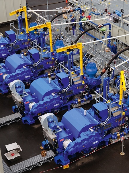
Small to medium-sized drilling rigs are mobile, such as those used in mineral exploration drilling, blast-hole, water wells and environmental investigations. Larger rigs are capable of drilling through thousands of metres of the Earth"s crust, using large "mud pumps" to circulate drilling mud (slurry) through the drill bit and up the casing annulus, for cooling and removing the "cuttings" while a well is drilled. Hoists in the rig can lift hundreds of tons of pipe. Other equipment can force acid or sand into reservoirs to facilitate extraction of the oil or natural gas; and in remote locations there can be permanent living accommodation and catering for crews (which may be more than a hundred). Marine rigs may operate thousands of miles distant from the supply base with infrequent crew rotation or cycle.
In the 1970s, outside of the oil and gas industry, roller bits using mud circulation were replaced by the first pneumatic reciprocating piston Reverse Circulation (RC) drills, and became essentially obsolete for most shallow drilling, and are now only used in certain situations where rocks preclude other methods. RC drilling proved much faster and more efficient, and continues to improve with better metallurgy, deriving harder, more durable bits, and compressors delivering higher air pressures at higher volumes, enabling deeper and faster penetration. Diamond drilling has remained essentially unchanged since its inception.
A typical oil production platform is self-sufficient in energy and water needs, housing electrical generation, water desalinators and all of the equipment necessary to process oil and gas such that it can be either delivered directly onshore by pipeline or to a floating platform or tanker loading facility, or both. Elements in the oil/gas production process include wellhead, production manifold, production separator, glycol proce


 8613371530291